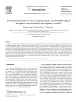
Development of nanosphere lithography and its applications 2
Bạn đang xem bản rút gọn của tài liệu. Xem và tải ngay bản đầy đủ của tài liệu tại đây (2.8 MB, 154 trang )
1
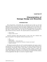
Chapter 1 Introduction
1.1 Introduction
Nanostructures and nanosystems have attracted much attention in modern
science and technology due to their unique physical and chemical properties, which
results in not only improving performance of current devices and processes but also
potentially generating many new applications in physical [1, 2], chemical [3, 4] and
bio technologies [5, 6].
Since the introduction of the theory of quantum mechanics in the twenty of last
century, it is a well known fact, that objects change their behavior if they approach a
certain lower size limit. Below this size limit, certain energies are allowed or
forbidden, sharp steps in energy spectra arise and the general physics of objects
change as shown in Fig.1.1. This quantum effects not only greatly improve some
device performance, such as high speed transistors [7] but also result in some totally
new devices like the semiconductor laser [8] or the superconducting nanowires [9].
Fig. 1.1 Quantum effects of matter.
2
So far it has been demonstrated that nanostructures exhibit particularly peculiar
and interesting characteristics, for example: quantized excitation [8], Coulomb
blockade [10], single-electron tunneling [11], and metal-insulator transition [12].
These phenomena occur in structures small enough for quantum mechanical effects to
dominate.
Besides the quantum effects, new phenomena result from the nanostructures or
nanosystems also occur and applied in physical, chemical and biotechnologies. For
example, ballistic movement of an electron in a semiconductor [13], near- and far-
field diffraction of visible light [14], diffusion of an active species close to an
electrode [15], excitation of collective resonance by light [16]. Fabrication and study
of these systems have become active areas of research in physics, material science,
chemistry and biology.
In addition, photonic crystals are periodic optical nanostructures that affect the
motion of photons in much the same way that ionic lattices affect electrons in solids.
Combining the quantum dots and the photonic crystals has already attracted much
attention [17-20].
However, how to fabricate such periodic nanostructures efficiently is still a big
challenge.
1.2 Review of nanofabrication technologies
The ability to fabricate structures from the micro- to the nanoscale with high
precision in a wide variety of materials is of crucial importance to the advancement of
micro- and nanotechnology and the nanosciences. The semiconductor industry has
been pushing high-precision nanoscale lithography to manufacture ever-smaller
transistors and higher-density integrated circuits (ICs). Critical issues, such as
resolution, reliability, speed, and overlay accuracy, all need to be addressed in order
to develop new lithography methodologies for such demanding, industrially relevant
3
processes. On the other hand, less stringent conditions are found in many other areas,
for example, photonics, micro- and nanofluidics, chip-based sensors, and most
biological applications. Beside traditional lithographical technologies, such as
photolithography, e-beam lithography, several alternative approaches towards
nanostructure fabrication have been exploited in the past 15 years. These techniques
include microcontact printing (or soft lithography) [21], nanoimprint lithography
(NIL) [22], scanning-probe-based techniques (e.g., atomic force microscope
lithography) [23], dip-pen lithography [24], and nanosphere lithography. In the thesis,
I will focus on the development of nanosphere lithography (NSL), and its various
applications, such as fabricating surface nanostructures, forming templates and
growing nanostructures through the templates.
Basically, lithography is a chemical process to pattern parts of a thin film or the
bulk of a substrate. These patterns can be formed on a mask and be transferred to
other thin film which can be used to form various small devices, such as integrated
circuit, MEMS and small devices including light emitting diodes. Traditional
lithographic techniques include photolithography [25], in which light is used as an
energy source to change the photoresist; e-beam lithography [26], in which electrons
are used to change the chemical properties of the resist. Recently various lithography
techniques, for example, nanoimprinting [22], and nanosphere lithography [27], have
been developed to overcome the problems arising from traditional lithographic
techniques.
1.2.1 Lithography with photons
The well known lithography is photolithography, which uses light to transfer a
geometric pattern from a photomask to a light-sensitive chemical "photoresist" on the
substrate. After development, a deposition or etch process is applied to form the
pattern on a film or a substrate as shown in Fig. 1.2.
4
Fig. 1.2 Basic outline of optical lithography processes. The diagram shows the optical
radiation entering the system, which is then filtered by the chromium mask. The
image is then projected on to the resist, and any non-exposed material is removed
during developing.
Photons have been used for many years to induce chemical reactions in
photographic materials or resist polymers. The lithographic technology is an
invaluable tool for micro-fabrication in a broad range of applications in science and
technology and one of the most widely used and highly developed technologies now
practiced [25]. In this process, the mask is placed in physical contact with, or in close
proximity to, the resist. Most fabrication in the integrated circuit industry uses such
lithography.
Photolithography is a fast technique to form patterns due to its large area expose.
The minimum feature size that can be obtained by this process is primarily
determined by diffraction that occurs as light passes through the gap between the
mask and the resist. Even with the use of elaborate vacuum systems to pull the mask
and substrate together, it is still difficult in practice to reduce the gap between a
conventional rigid mask and a rigid flat substrate to less than ~1 µm over large areas.
As a result [28], the resolution of contact mode photolithography is typically 0.5-0.8
5
µm when UV light (360-460 nm) is used. The resolution of photolithography
increases as the wavelength of the light used for exposure decreases. Feature sizes of
250 nm can be obtained when 248 nm UV light is used. However, there are big
problem with transparency of optical parts when wavelength of light is further
decreased [29].
Although photolithography was demonstrated with soft EUV and X-rays many
years ago, to fabricate the masks and optics capable of supporting a robust,
economical method still provides significant unsolved challenges [30].
1.2.2 Lithography with Particles
Fig. 1.3 Basic electron optical column in which the beam is formed. The image is
formed on the resist, and the deflectors control the position of the beam on the resist.
Theoretically, photolithography can get the resolution down to 30 nm at X-Ray
wavelengths. However, as finer resolutions are demanded by industry, shorter
wavelengths must be used. Gamma rays cannot be used, as the mask nor the resist
6
will absorb them. From the quantum mechanical principle of wave-particle duality
[31] and the de Broglie equation
, it is found that an electron with an
energy of 10 keV has a wavelength of around 12 pm. This obviously represents a
huge reduction in wavelength compared to X-Ray radiation, and therefore electron
beam lithography has the possibility at a better resolution than any of the
electromagnetic methods previously considered.
Electron beam lithography replaces the photons with an electron beam, and
utilizes a different system with image formation between the source and the resist
with no mask in the system (Fig. 1.3).
Because of using a beam of electrons, whose direction can be controlled by a
magnetic field, there is no need for a mask in the lithographic system. A computer
controls the strength of the magnetic field, whilst there is very little diffraction from
the electrons, so the patterns produced on the resist are extremely accurate, even
though it suffers from scattering in the resist. Less than 10 nm features has been
obtained by this technique [32]. However, electron beam lithography still accounts a
big problem. The system has a very low throughput due to its series nature of writing,
only one point on the resist can be exposed at any given time.
1.2.3 Nanoimprinting
The principle of nanoimprinting is very simple. Figure 1.4a shows a schematic
of the originally proposed NIL process [33, 34].
A hard mold that contains nanoscale surface-relief features is pressed into a
polymeric material cast on a substrate at a controlled temperature and pressure,
thereby creating a thickness contrast in the polymeric material. A thin residual layer
of polymeric material is intentionally left underneath the mold protrusions, and acts
as a soft cushioning layer that prevents direct impact of the hard mold on the substrate
and effectively protects the delicate nanoscale features on the mold surface.
7
Fig.1.4 (a) Schematic of the originally proposed NIL process. (b) Scanning electron
microscopy (SEM) image of a fabricated mold with a 10 nm diameter array. (c) SEM
image of hole arrays imprinted in poly(methyl methacrylate) by using such a mold
[34].
Advantages of the NIL are that it demonstrated ultrahigh resolutions soon after
its inception. Figures 1.4 b and c show SEM images of a mold with a pillar array
(pillar diameter 10 nm) and an imprinted 10 nm hole array in poly(methyl
methacrylate) (PMMA) that were obtained almost a decade ago [35]. NIL is
inherently high-throughput, because of parallel printing, and it requires only a simple
equipment, leading to low-cost processes. A variation of the NIL technique that uses
a transparent mold and UV-curable precursor liquid to define the pattern (step-and-
flash imprint lithography) has been demonstrated [36], allowing the process to be
carried out at room temperature and making it attractive for IC semiconductor device
manufacturers.
8
However, it still has some challenges in meeting the stringent requirements of
various applications, such as mold fabrication, mold surface preparation, NIL resist,
and residual layer problem [34].
1.3 Nanosphere lithography
Nanosphere lithography (NSL) is an inexpensive, simple to implement,
inherently parallel, high throughput general nanofabrication technique capable of
producing an unexpectedly large variety of nanostructures and well-ordered 2D
nanostructural arrays.
and Zingsheim with th -assembled polystyrene latex
nanospheres as a mask for contact imaging with visible light in 1981 [37]. In 1982,
Deckman and co-
demonstrating that a self-assembled nanosphere monolayer could be used as both a
describe this process. Deckman and co-workers continued to explore various
fabrication parameters and possible applications of natural lithography but always
employed a single layer (SL) of nanospheres as the mask [38]. The third stage in the
evolution of natural lithography, renamed nanosphere lithography (NSL) to be more
operationally descriptive, is represented by the work of Van Duyne et al. [39], who
extended the SL methodology with (1) the development of a double layer (DL)
nanosphere mask, (2) atomic force microscopy (AFM) studies of SL and DL periodic
particle arrays (PPAs) of Ag on mica, and (3) fabrication of defect-free SL and DL
PPAs of Ag on mica with areas of 10-100 µm
2
that were large enough to permit
microprobe studies of nanoparticle optical properties [39]. As an efficient
nanofabrication technique, NSL is being used in laboratories around the world to
9
study the size-dependent optical, magnetic, electrochemical, thermodynamic, and
catalytic properties of materials.
Fig. 1.5 (a) side and (b) top-views of self-assembly of nanospheres
It has been demonstrated that the self-assembly process to form 2D ordered
arrangement of the nanospheres starts from a nucleation [40]. The nucleus formation
is governed by attractive capillary forces appearing between spheres partially
immersed in a liquid layer. Then, crystal growth occurs through convective particle
flux caused by the water evaporation from the already ordered array (Fig. 1.5). In
principle, the monolayer of hexagonally close-packed (hcp) spheres can be used as a
mask to form nanoparticles by depositing other materials through the holes between
the spheres. Actually, nanostructures can also be created on the substrate by dry
etching or infiltrating process as seen in Fig. 1.6.
Methods to deposit a nanosphere solution onto the desired substrate include spin
coating [41], drop coating [42], template-directed growth [43], angled cooling plates
and Langmuir-Blodgett techniques [44]. All these deposition methods require that the
10
nanospheres are able to freely diffuse across the substrate, seeking their lowest energy
configuration. This is often achieved by chemically modifying the nanosphere surface
Fig. 1.6 Nanosphere lithography used to create various nanostructures
with a negatively charged functional group, such as carboxylate or sulfate that is
electrostatically repelled by the negatively charged surface of a substrate such as mica
or glass. Following the self-assembly of the nanosphere mask, a metal or other
material is then deposited by thermal evaporation, electron beam deposition (EBD),
or pulsed laser deposition from a source normal to the substrate through the
nanosphere mask to a controlled mass thickness d
m
. After the metal deposition, the
nanosphere mask is removed by sonicating the entire sample in a solvent, leaving
behind the material deposited through the nanosphere mask on the substrate.
In the simplest NSL case, only a monolayer of hcp nanospheres with a diameter
of D is self-assembled onto the substrate. When one deposits metal through the
monolayer mask, the three-fold interstices allow deposited metal to reach the
substrate, creating an array of triangular shaped nanoparticles with P
6mm
symmetry
[Figs. 1.7(a) and (b)]. Simple geometric calculations define the relationship between
11
the perpendicular bisector of the triangular nanoparticles a and the interparticle
spacing d
ip
to the nanosphere diameter D as shown in Fig 1.7(e).
(1)
(2)
When a second layer of nanospheres assembles onto the first, every other three-
fold hole is blocked, and a smaller density of six-fold interstices results. After
depositing metal through the double layer (DL) nanosphere mask, a regular pattern of
hexagonal nanoparticles forms on the substrate [Figs. 1.7(c) and (d)]. This array is
referred to be a DL PPA. As in the SL PPA, the size of the DL PPA nanoparticles can
be tuned by the deposited nanosphere size and the d
m
. Similarly as illustrated in Fig
1.7(f),
(3)
(4)
There are two possible outcomes when a third layer of nanospheres assembles
onto a DL: (1) if the nanospheres pack in an ABAB sequence, the regular pattern of
hexagonal holes remains or (2) if the nanospheres pack in an ABCABC sequence, all
the mask holes are blocked. Therefore, a nanosphere mask containing three or more
layers in the ABCABC stacking sequence does not allow any deposited materials to
reach the substrate.
Beside nanodots, other nanostructures can also be formed through the NSL, for
example nanoring [39]. During deposition of nickel by EBD, nanorings have been
observed as shown in Fig. 1.8. In this case, it seems that bimodal kinetic energy
distribution of gas-phase atoms are produced by EBD. Low kinetic energy (~0.1 eV)
atoms that travel along a direct line of sight from the EBD target to the substrate and
stick where they strike the substrate form the triangular nanodots. In contrast, high
kinetic energy (~1-10 eV) atoms that travel along off-normal trajectories strike the
12
and then continue to travel, because of excess kinetic energy, adhering to the
substrate underneath the nanosphere to form the nanorings. These nanorings can also
be used as masks to create thin-walled nanocylinders.
Fig. 1.7 Schematic illustration (a) and representative AFM image (b) of SL PPA. The
AFM image was captured from a SL PPA fabricated with D = 542 nm nanospheres
and d
m
= 48 nm thermally evaporated Ag metal after removing the nanospheres;
Schematic illustration (c) and representative AFM image (d) of DL PPA. The AFM
image was captured from a SL PPA fabricated with D = 400 nm nanospheres and d
m
=
30 nm thermally evaporated Ag metal after removing the nanospheres [39]. (e) and (f)
show the definition of the parameters of D, a and d
ip
for single and double layer
arrangement, respectively.
In addition, some modified NSLs, such as Angle-Resolved Nanosphere
Lithography, have also been developed to form unique shaped nanostructures [46].
For example, they are nanooverlaps, nanogaps and nanoparticle chains as seen in Fig
1.9.
In the aforementioned nanoparticle architectures, all materials were deposited
from a collimated source along a line perpendicular to the plane of the nanosphere
mask. A new class of NSL structures has been fabricated by varying the angle
between the nanosphere mask and the beam of material being deposited. The size and
shape of the three-fold interstices of the nanosphere mask change relative to the
13
deposition source as a function of
, and accordingly, the deposited
shape and size are controlled directly by
(Figure 1.9).
Fig. 1.8 Schematic illustration (a) and representative AFM image (b) of nanoring and
SL PPA fabrication. The AFM image was captured from a sample fabricated with D
= 979 nm nanospheres and d
m
= 50 nm e-beam deposited Ni metal after removing the
nanospheres [39].
Although the nanostructures created through the NSL have many applications in
nanophotonics, catalysis, and biotechnologies [39-46], as in all naturally occurring
crystals, nanosphere masks include a variety of defects that arise as a result of
nanosphere polydispersity, site randomness, point defects (vacancies), line defects
(slip dislocations), and polycrystalline domains. Especially, it is difficult to obtain a
single layer over a large area, which limits its applications because nanostructures
created by different layer(s) are totally different. Physical and chemical properties of
the nanostructures depend seriously on the shapes. Most nanostructures created by the
NSL are hexagonally arranged and controlling the shape of the nanostructures in the
plane and in the vertical direction is also a big challenge.
14
Fig. 1.9 Schematic of the angle resolved deposition process. (a) Samples viewed at 0°
(a), 30°, (b) and 45°, (c), respectively [46].
1.4 Motivation and objectives
Although nanosphere lithography (NSL) has been recognized as an inexpensive,
high throughput, and flexible technology to fabricate nanostructures, there are two
main problems limit its further applications - 1) how to obtain pure single or double
layer of the nanospheres over a large area. It is known that nanostructures fabricated
through single and double layered arrays of the nanospheres are totally different. So
this technology is hardly to use in device applications if a pure single or double
layered array of the nanospheres cannot be obtained in a device level 2) how to
control the shapes of the nanostructures fabricated through the NSL. So far, only
nanostructures with limited shapes can be fabricated by the NSL due to the nature of
the spherical particles and its 2D hexagonal arrangement of the nanospheres. So, the
objectives of my work are:
1. To develop techniques to overcome above mentioned problems, which
include: controlling arrangement of the nanospheres in areas as larger as the
device required; controlling shapes of the nanostructures fabricated by the
NSL in both vertical and lateral directions.
15
2. To investigate applications of the nanostructures, as templates, fabricated by
the NSL, which include: MOCVD nano-growth of III-V compound;
fabricating metal nanostructures and applying nanostructures created by
NSL to enhance LED performances.
1.5 Scope of thesis
Chapter 1 summarizes some technologies for nanofabrication. The working
principle, advantages and disadvantages of nanosphere lithography are discussed.
Focusing on overcoming the weaknesses of nanosphere lithography, a method for
obtaining either a single layer or double layer of nanospheres on an entire area as
large as a light emitting diode (LED), is described in Chapter 2. Some techniques,
such as multi-cycle-etching, used to create 3D surface nanostructures; 3D masks,
used to fabricate more complex nanostructures and a one step method to fabricate
nanostructures with multi-size features, have been demonstrated in this chapter. In
addition, RIE behaviors in controlling shapes of nanostructures in vertical and lateral
directions are also systemically investigated in the chapter 2.
Some nanostructures created by methods discussed in Chapter 2 are used as
templates to investigate nano-epi-growth of semiconductor nanostructures, which are
discussed in Chapter 3. An ordered array of InGaAs/GaAs nanobars has been
obtained by MOCVD through a SiO
2
template created by nanospheres lithography.
Especially, combining photolithography, such template can be formed so that the
nanobars can be grown on selected regions, or such arrays of InGaAs/GaAs nanobars
with multi-sized features can be grown in one step MOCVD. In addition, growth of
GaN films on Si nanopillars formed on a Si substrate is also presented in the chapter
3.
In Chapter 4, metal nanostructures created by the templates described in Chapter
2 are presented together with their optical properties. The nanostructures are ordered
16
3D Au nanostructures formed through a 2D polymer nanosphere array and ordered
Ag nanoparticles with excellent uniformity formed by a template guided annealing
process. Mechanism of forming the uniform, well arranged Ag nanoparticles is also
discussed in this chapter.
In Chapter 5, nanostructures created through nanosphere arrays are applied to
LEDs to enhance light extraction. Red LEDs grown on a GaAs substrate and blue
LEDs grown on a sapphire substrate are used. In addition, Au honeycomb
nanostructures fabricated through nanosphere lithography on a red LED is also
presented.
In Chapter 6, I have summarized the results obtained mainly from the developed
techniques.
References
[1] M. Grundmann, J. Christen, N. N. Ledentsov, J. Böhrer, D. Bimberg, S. S.
Ruvimov, P. Werner, U. Richter, U. Gösele, J. Heydenreich, V. M. Ustinov, A.
Luminescence Lines from Single Quantu Phys. Rev. Lett. 74, 4043
(1995).
[2] P. Bhattacharya, S. Ghosh, A. D. Stiff-uantum Dot Opto-electronic
DevicesAnnu. Rev. Mater. Res. 34, 1 (2004).
[3] Haiping M. Chen, Lin Pang, Andrew King, Grace M. Hwang and Yeshaiahu
Fainman
[4] Paul L. Stiles, Jon A. Dieringer, Nilam C. Shah, and Richard P. Van Duyne,
-
(2008).
[5] Marinus A. Otte, M Carmen Estevez, Laura G. Carrascosa, Ana B. Gonzalez-
Guerrero, Laura M. Lechug
(2011).
[6] Mrinmoy De, Partha S. Ghosh, Vincent M. Applications of Nanoparticles in
Biology, Adv. Mater. 20, 4225 (2008).
[7] T. Ashley, L. Buckle, S. Datta, M.T. Emeny, D.G. Hayes, K.P. Hilton, R.
Jefferies, T. Martin, T.J. Phillips, D.J. Wallis, P.J. Wilding and R. Chau,
Heterogeneous InSb quantum well transistors on silicon for ultra-high speed,
low power logic applications, Electronics Letters 43, 0013-5194 (2007).
[8] S. Fafard, K. Hinzer, S. Raymond, M. Dion, J. McCaffrey, Y. Feng, S.
Charbonneau, Red-Emitting Semiconductor Quantum Dot Lasers, Science 274,
1350 (1996).