TIME DOMAIN MEDIUM ACCESS CONTROL PROTOCOLS FOR UNDERWATER ACOUSTIC NETWORKS
Bạn đang xem bản rút gọn của tài liệu. Xem và tải ngay bản đầy đủ của tài liệu tại đây (2.86 MB, 268 trang )
TIME DOMAIN MEDIUM ACCESS
CONTROL PROTOCOLS FOR
UNDERWATER ACOUSTIC NETWORKS
SHIRAZ SHAHABUDEEN
NATIONAL UNIVERSITY OF SINGAPORE
2011
ii
TIME DOMAIN MEDIUM ACCESS
CONTROL PROTOCOLS FOR
UNDERWATER ACOUSTIC NETWORKS
SHIRAZ SHAHABUDEEN
(B.Eng., NUS, M.Tele.Eng., University of Melbourne)
A THESIS SUBMITTED
FOR THE DEGREE OF DOCTOR OF PHILOSOPHY
DEPARTMENT OF ELECTRICAL AND COMPUTER ENGINEERING
NATIONAL UNIVERSITY OF SINGAPORE
2011
ii
Acknowledgments
This work would not have been possible if not for the support from Acoustic
Research Laboratory and the Defence Science Technology Agency (DSTA), Sin-
gapore, under the guidance of Dr. Mandar Chitre and Dr. Mehul Motani. Many
of my close colleagues at ARL have been of immense help in this endeavour, es-
pecially Dr. John Potter, Dr. Venugopalan Pallayil, Mr. Mohan Panayamadam,
Mr. Shankar Satish, Mr. Alan Low, Mr. Koay Teong Beng and Mr. Iulian Topor.
i
ii
Dedication
This work is dedicated to my parents and my dear wife who have been my
support throughout, and also to the rest of my wonderful family.
iii
iv
Contents
Summary xv
List of Figures xvii
List of Symbols xxv
Abbreviations xxix
Chapter 1 Introduction 1
1.1 Background and Motivation . . . . . . . . . . . . . . . . . . . . . . 2
1.2 Objectives . . . . . . . . . . . . . . . . . . . . . . . . . . . . . . . . 4
1.3 Methodology . . . . . . . . . . . . . . . . . . . . . . . . . . . . . . 6
1.4 Outline . . . . . . . . . . . . . . . . . . . . . . . . . . . . . . . . . . 7
1.5 Novel Contributions . . . . . . . . . . . . . . . . . . . . . . . . . . . 8
Chapter 2 Literature Review 11
2.1 Media Access Control . . . . . . . . . . . . . . . . . . . . . . . . . . 11
2.1.1 Static protocols . . . . . . . . . . . . . . . . . . . . . . . . . 12
2.1.2 Dynamic contention-based MAC . . . . . . . . . . . . . . . . 13
2.1.3 Conflicting opinions and results . . . . . . . . . . . . . . . . 15
v
2.1.4 Dynamic contention-free MAC . . . . . . . . . . . . . . . . . 15
2.2 Energy Conservation . . . . . . . . . . . . . . . . . . . . . . . . . . 16
2.3 AUV Networking . . . . . . . . . . . . . . . . . . . . . . . . . . . . 17
2.4 Standardization and Software Frameworks . . . . . . . . . . . . . . 17
2.5 Conclusion . . . . . . . . . . . . . . . . . . . . . . . . . . . . . . . . 18
Chapter 3 Investigation of MAC Protocol Choices for UANs 21
3.1 Introduction . . . . . . . . . . . . . . . . . . . . . . . . . . . . . . . 21
3.1.1 Topology . . . . . . . . . . . . . . . . . . . . . . . . . . . . . 23
3.1.2 Spatial re-use, channelization and allocation . . . . . . . . . 25
3.1.3 Need for dynamic channelization and allocation in UANs . . 27
3.2 Selection of MAC Protocols for UANs . . . . . . . . . . . . . . . . . 28
3.2.1 The general equivalence of static TDMA, FDMA and CDMA 29
3.2.2 General strengths and weaknesses of CDMA, FDMA and
TDMA . . . . . . . . . . . . . . . . . . . . . . . . . . . . . . 31
3.2.2.1 Full duplex requirement for CDMA and FDMA . . 32
3.2.2.2 CDMA performs better in terrestrial cellular net-
works? . . . . . . . . . . . . . . . . . . . . . . . . . 34
3.2.3 Dynamic allocation protocols . . . . . . . . . . . . . . . . . 36
3.2.4 Dynamic TDMA protocol and MACA based protocols . . . 38
3.2.5 Re-use, topology selection . . . . . . . . . . . . . . . . . . . 41
3.2.6 Propagation delay and its impact . . . . . . . . . . . . . . . 42
3.3 Conclusion . . . . . . . . . . . . . . . . . . . . . . . . . . . . . . . . 43
vi
Chapter 4 A high performance MAC protocol for underwater acous-
tic networks: MACA-EA 45
4.1 Review . . . . . . . . . . . . . . . . . . . . . . . . . . . . . . . . . . 45
4.2 System Model . . . . . . . . . . . . . . . . . . . . . . . . . . . . . . 49
4.2.1 Input-output models . . . . . . . . . . . . . . . . . . . . . . 49
4.2.2 Packet detection, error and collision model . . . . . . . . . . 50
4.2.3 MACA-based protocol model . . . . . . . . . . . . . . . . . 51
4.2.4 Performance measures . . . . . . . . . . . . . . . . . . . . . 52
4.2.5 A brief note on simulations . . . . . . . . . . . . . . . . . . 54
4.3 Analysis of Service Time and Throughput . . . . . . . . . . . . . . 55
4.3.1 Markov chain model for the protocol excluding retries . . . . 55
4.3.2 Enhanced retry mechanism . . . . . . . . . . . . . . . . . . . 61
4.3.3 Expected throughput for reliable transfer . . . . . . . . . . . 65
4.3.4 Expected packet service time s
p
. . . . . . . . . . . . . . . . 67
4.3.5 Comparison with previous analyses . . . . . . . . . . . . . . 67
4.3.6 Sea trial results . . . . . . . . . . . . . . . . . . . . . . . . . 68
4.4 Service Time Distribution Analysis . . . . . . . . . . . . . . . . . . 71
4.5 Queuing Analysis . . . . . . . . . . . . . . . . . . . . . . . . . . . . 75
4.5.1 Unsaturated queuing analysis . . . . . . . . . . . . . . . . . 75
4.5.2 Expected waiting time . . . . . . . . . . . . . . . . . . . . . 77
4.5.3 Waiting time variation with batch size . . . . . . . . . . . . 79
4.6 Protocol Enhancement: MACA-SEA . . . . . . . . . . . . . . . . . 83
4.6.1 Algorithm outline . . . . . . . . . . . . . . . . . . . . . . . . 84
vii
4.6.2 MACA-SEA performance . . . . . . . . . . . . . . . . . . . 85
4.7 Discussion . . . . . . . . . . . . . . . . . . . . . . . . . . . . . . . . 86
4.7.1 Pre-emptive contention . . . . . . . . . . . . . . . . . . . . . 86
4.7.2 Optimum RTS window . . . . . . . . . . . . . . . . . . . . . 89
4.7.3 Physical Carrier Sense . . . . . . . . . . . . . . . . . . . . . 91
4.7.4 Single Long DATA Instead of Batches . . . . . . . . . . . . 91
4.7.5 Optimum number of ACKs . . . . . . . . . . . . . . . . . . . 92
4.7.6 Forward Error Correction (FEC) and Power Control . . . . . 93
4.7.7 Multi-hop and hidden nodes . . . . . . . . . . . . . . . . . . 94
4.8 Conclusion . . . . . . . . . . . . . . . . . . . . . . . . . . . . . . . . 95
Chapter 5 Adaptive Multi-mode Medium Access Control for Un-
derwater Acoustic Networks 99
5.1 Introduction . . . . . . . . . . . . . . . . . . . . . . . . . . . . . . . 100
5.2 Protocol Modes in MAC-AMM . . . . . . . . . . . . . . . . . . . . 102
5.2.1 Level-1 compliance . . . . . . . . . . . . . . . . . . . . . . . 102
5.2.2 Level-2 compliance . . . . . . . . . . . . . . . . . . . . . . . 104
5.2.3 Distributed mode of Level-2 MAC: MACA-EA . . . . . . . . 105
5.2.4 Centralized mode of Level-2 MAC: MACA-C . . . . . . . . . 106
5.2.5 Level-2 distributed mode with no handshaking: DATA-ACK 107
5.2.6 Adaptive multi-mode MAC . . . . . . . . . . . . . . . . . . 107
5.3 Throughput Analysis of LEVEL-2 MAC . . . . . . . . . . . . . . . 109
5.3.1 DATA-ACK . . . . . . . . . . . . . . . . . . . . . . . . . . . 110
5.3.2 MACA-EA . . . . . . . . . . . . . . . . . . . . . . . . . . . 111
viii
5.3.3 MACA-C . . . . . . . . . . . . . . . . . . . . . . . . . . . . 111
5.4 Mode Adaptation Based on Traffic Intensity . . . . . . . . . . . . . 115
5.4.1 Service time distribution . . . . . . . . . . . . . . . . . . . . 116
5.4.2 MACA-EA . . . . . . . . . . . . . . . . . . . . . . . . . . . 118
5.4.3 MACA-C . . . . . . . . . . . . . . . . . . . . . . . . . . . . 118
5.4.4 DATA-ACK . . . . . . . . . . . . . . . . . . . . . . . . . . . 120
5.4.5 TDMA-REF . . . . . . . . . . . . . . . . . . . . . . . . . . . 121
5.4.6 Effect of traffic intensity . . . . . . . . . . . . . . . . . . . . 123
5.4.7 Adaptation algorithm . . . . . . . . . . . . . . . . . . . . . . 126
5.5 State dependent DATA-ACK protocol . . . . . . . . . . . . . . . . 130
5.6 Discussion . . . . . . . . . . . . . . . . . . . . . . . . . . . . . . . . 130
5.7 Conclusion . . . . . . . . . . . . . . . . . . . . . . . . . . . . . . . . 132
Chapter 6 Twin-MAC Protocols 135
6.1 Introduction . . . . . . . . . . . . . . . . . . . . . . . . . . . . . . . 136
6.1.1 Throughput greater than 1? . . . . . . . . . . . . . . . . . . 136
6.1.2 2-node network . . . . . . . . . . . . . . . . . . . . . . . . . 137
6.1.3 4-node regular tetrahedron network . . . . . . . . . . . . . . 138
6.1.4 4-node stretched tetrahedron network . . . . . . . . . . . . . 140
6.1.5 N-node networks . . . . . . . . . . . . . . . . . . . . . . . . 141
6.1.6 Bounded network geometries . . . . . . . . . . . . . . . . . . 143
6.1.7 Remarks . . . . . . . . . . . . . . . . . . . . . . . . . . . . . 145
6.2 Pair-wise Transmission Protocols . . . . . . . . . . . . . . . . . . . 145
6.2.1 Twin-TDMA . . . . . . . . . . . . . . . . . . . . . . . . . . 147
ix
6.2.1.1 Throughput . . . . . . . . . . . . . . . . . . . . . . 147
6.2.1.2 Queuing delay . . . . . . . . . . . . . . . . . . . . 150
6.2.2 Dynamic Twin-TDMA . . . . . . . . . . . . . . . . . . . . . 152
6.2.2.1 Centralized dynamic Twin-TDMA . . . . . . . . . 153
6.2.2.2 Performance . . . . . . . . . . . . . . . . . . . . . 154
6.2.3 Twin-ALOHA . . . . . . . . . . . . . . . . . . . . . . . . . . 155
6.3 Conclusion . . . . . . . . . . . . . . . . . . . . . . . . . . . . . . . . 158
Chapter 7 A Multi-channel MAC Protocol for AUV Networks 159
7.1 Introduction . . . . . . . . . . . . . . . . . . . . . . . . . . . . . . . 159
7.2 Multi-channel Modelling . . . . . . . . . . . . . . . . . . . . . . . . 161
7.2.1 BER performance modelling . . . . . . . . . . . . . . . . . . 161
7.2.2 The packet train model and packet loss ratio . . . . . . . . . 163
7.3 Network Architecture and Algorithms . . . . . . . . . . . . . . . . . 165
7.3.1 The physical layer . . . . . . . . . . . . . . . . . . . . . . . . 165
7.3.2 Network layer and data transmission model . . . . . . . . . 165
7.3.3 The overall architecture . . . . . . . . . . . . . . . . . . . . 166
7.3.4 The basic DLL algorithm . . . . . . . . . . . . . . . . . . . . 166
7.4 Simulation Setup . . . . . . . . . . . . . . . . . . . . . . . . . . . . 168
7.4.1 Modelling of AUV node motion . . . . . . . . . . . . . . . . 168
7.4.2 Some factors affecting performance . . . . . . . . . . . . . . 170
7.5 Simulation Results . . . . . . . . . . . . . . . . . . . . . . . . . . . 170
7.5.1 MACA-MCP effective data rate performance . . . . . . . . . 171
7.5.2 MACA-MCP throughput performance . . . . . . . . . . . . 173
x
7.5.3 Adaptive clustering behaviour . . . . . . . . . . . . . . . . . 175
7.6 Conclusion . . . . . . . . . . . . . . . . . . . . . . . . . . . . . . . . 176
Chapter 8 Unified Simulation and Implementation Software Frame-
work 177
8.1 Introduction . . . . . . . . . . . . . . . . . . . . . . . . . . . . . . . 177
8.2 FAPI and UNA . . . . . . . . . . . . . . . . . . . . . . . . . . . . . 180
8.3 ARL Modem . . . . . . . . . . . . . . . . . . . . . . . . . . . . . . 182
8.4 The Simulator . . . . . . . . . . . . . . . . . . . . . . . . . . . . . . 183
8.4.1 The unified simulator and modem software model . . . . . . 184
8.4.2 Simulator physical layer details . . . . . . . . . . . . . . . . 185
8.4.3 Channel model details . . . . . . . . . . . . . . . . . . . . . 187
8.4.4 Simulator limitations . . . . . . . . . . . . . . . . . . . . . . 188
8.5 Writing MAC Code . . . . . . . . . . . . . . . . . . . . . . . . . . . 189
8.6 Modem Trials and Results . . . . . . . . . . . . . . . . . . . . . . . 191
8.6.1 Sea trials . . . . . . . . . . . . . . . . . . . . . . . . . . . . 192
8.7 Conclusion . . . . . . . . . . . . . . . . . . . . . . . . . . . . . . . . 194
Chapter 9 Conclusion 195
9.1 Future Work . . . . . . . . . . . . . . . . . . . . . . . . . . . . . . . 198
Bibliography 201
Appendix A MACA Analysis 213
A.1 The Performance of the Standard ACK Model . . . . . . . . . . . . 213
A.2 Distribution Analysis Markov Chain . . . . . . . . . . . . . . . . . 213
xi
Appendix B Analysis for MAC-AMM 216
B.1 DATA-ACK throughput analysis . . . . . . . . . . . . . . . . . . . 216
B.2 M/D
B
/1 Waiting Time Analysis for MACA-C and TDMA . . . . . 220
B.3 Inter-cell or inter-MC interference . . . . . . . . . . . . . . . . . . . 220
Appendix C Super TDMA 223
C.1 Prototype Schedule for Odd-even Distance Networks . . . . . . . . 223
C.2 ρ-schedule . . . . . . . . . . . . . . . . . . . . . . . . . . . . . . . . 224
Appendix D UNA, FAPI, DLL Utilities and Sample MAC Code 225
D.1 UNA Messages . . . . . . . . . . . . . . . . . . . . . . . . . . . . . 225
D.1.1 Key physical layer messages . . . . . . . . . . . . . . . . . . 225
D.1.2 Key data link layer messages . . . . . . . . . . . . . . . . . . 225
D.2 Framework API . . . . . . . . . . . . . . . . . . . . . . . . . . . . . 226
D.3 Data link layer Utility Functions . . . . . . . . . . . . . . . . . . . . 227
D.3.1 Reception handling . . . . . . . . . . . . . . . . . . . . . . . 227
D.3.2 HPA control . . . . . . . . . . . . . . . . . . . . . . . . . . . 227
D.3.3 PDU handlers . . . . . . . . . . . . . . . . . . . . . . . . . . 228
D.4 Sample MAC Code . . . . . . . . . . . . . . . . . . . . . . . . . . . 229
D.4.1 The main handler interface . . . . . . . . . . . . . . . . . . . 229
D.4.2 MAIN MAC HANDLER . . . . . . . . . . . . . . . . . . . . 230
D.4.3 DLL SEND PKT REQ . . . . . . . . . . . . . . . . . . . . . 230
D.4.4 FAPI TIMER EXPIRED NTF . . . . . . . . . . . . . . . . 231
D.4.5 PHY PKT XMIT RSP . . . . . . . . . . . . . . . . . . . . . 231
D.4.6 PHY INCOMING PKT NTF . . . . . . . . . . . . . . . . . 232
xii
Appendix E Publications From This Thesis 233
xiii
xiv
Summary
The central objective of this thesis is an investigation of time domain
medium access control (MAC) protocols, specifically those based on Medium Ac-
cess Collision Avoidance (MACA), for Underwater Acoustic Networks (UAN). A
review of the key developments in data link layer (DLL) at the start of the work
revealed many gaps in research on the relative merits of MAC protocols for UANs
and the performance of protocols. Re-analysis of the design choices for MAC in
UANs led to the observation that in a distributed topology, CDMA and FDMA
require full-duplex and multi-channel functionality to have similar performance as
TDMA. Time domain protocols, including those based on MACA, are found to be
fundamentally best suited for UAN MAC.
A key objective was to develop new high performance MACA-based pro-
tocols for UANs. A novel ARQ variation called Early-Multi-ACK for batch-node
data transmissions and some other enhancements to MACA give rise to the novel
MACA-EA protocol. An in-depth analysis of this protocol, including factors such
as propagation delay, detection and decoding errors not considered in many pre-
vious analyses, gives new closed form metrics for mean service time and through-
xv
put for reliable batch transmission. The batch service time distribution closely
matches the exponential distribution. Queuing analysis of the waiting time shows
that there is an optimum batch size that minimizes total waiting time.
Other novel protocol refinements have been developed such as the MACA-
SEA protocol, that can achieve higher performance through a pseudo-TDMA “tak-
ing turns” behaviour. A novel multi-channel protocol called MACA-MCP for
effective networking in a small AUV network, exploits mobility through multiple
acoustic modems operating at different frequency bands suited for different ranges.
A multi-mode protocol suite – MAC-AMM, incorporates novel adaptation tech-
niques and uses a centralized MACA-C protocol mode, a distributed MACA-EA
mode and a novel state dependent DATA-ACK mode to achieve efficient com-
munications under varying environmental and traffic intensity. Motivated by a
recently published observation that in an N-node UAN, the upper bound nor-
malized throughput is N/2 and not 1 as is the case in networks with negligible
propagation delay, three novel protocols – Twin-TDMA, Dynamic Twin-TDMA
and Twin-ALOHA that utilize simultaneous transmissions were also developed.
A new unified software framework has been developed that aids seamless
simulations and sea-trials with the same MAC code, which helped ensure that the
performance measures in this thesis are reliable and the protocols are guaranteed
to work in real acoustic modems.
xvi
List of Figures
3.1 An example UAN architecture with two cells, one using a centralized
topology while the other using a distributed topology (Chitre et al.,
2008) . . . . . . . . . . . . . . . . . . . . . . . . . . . . . . . . . . . 25
3.2 A schematic representation of D-TDMA, D-FDMA and D-CDMA. . 37
3.3 MACA protocol model with RTS/CTS/PACKET-TRAIN. Node A
sends an RTS to Node B and Node B sends a CTS back to Node
A. Node A then sends a DATA batch to Node B. Reception of CTS
at another node C is shown which then performs a VCS to avoid
interference with Node A’s transmission. A potential collision from
Node C is shown. How back-off starts after completion of one batch
transmission is also indicated. . . . . . . . . . . . . . . . . . . . . . 39
4.1 Main Markov chain for computing expected service time . . . . . . 57
4.2 Markov chain for Early-Multi-ACK . . . . . . . . . . . . . . . . . . 63
4.3 Throughput vs. batch size for k = k
D
= 0.36, 0.49, 0.81 and 1.0,
simulations (S), analysis (A). Parameters: L = L
D
= 0.5s, N =
3, D = 0.5s, W = 4, i = 3. . . . . . . . . . . . . . . . . . . . . . . . 65
xvii
4.4 Throughput vs. batch size. Parameters: [L = 0.5s, k = 0.81, N =
3, D = 0.5s, W = 9, i = 3] . . . . . . . . . . . . . . . . . . . . . . . 66
4.5 Markov chain to compute s
p
. . . . . . . . . . . . . . . . . . . . . . 67
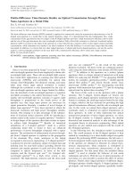
4.6 Analysis comparison with sea trials and simulations. Parameters:
N = 3, D = 0.4s, W = 10, P
d
= 1, P = 0.9, i = 1, L = 0.9s, L
d
=
0.6s. A sample image that was transferred between modems in a
recent sea trial is also shown. This file transfer used the MACA
based protocol with the Early-ACK retry mechanism. . . . . . . . . 70
4.7 Part of Markov chain with dummy states for computing service time
distribution . . . . . . . . . . . . . . . . . . . . . . . . . . . . . . . 71
4.8 Service time CDF. Parameters: L = L
D
= 0.5s, N = 3, D =
0.5s, W = 4, i = 3, k = k
D
= 0.81. “Analytical” curve uses Ex-
ponential fit. . . . . . . . . . . . . . . . . . . . . . . . . . . . . . . . 73
4.9 W
T
(in seconds) vs. Batch size (B), Parameters: L = L
D
=
0.5s, N = 3, D = 0.5s, W = 4, i = 3, λ = 0.05, k = k
D
= 0.81 . . . . 80
4.10 W
T
(in seconds) vs. Batch size (B), N = 10, D = 1.0s, L =
0.5s, L
D
= 1.5s, k = 0.81, k
D
= 0.9, W = 23, i = 3, λ = 0.033 . . . . 81
4.11 Variation of optimum (‘Opt’) and minimum (‘Min’) batch size with
the number of nodes N and arrival delays. Parameters: L = L
D
=
0.5s, N = 3, D = 0.5s, W = 4, i = 3, k = k
D
= 0.81. . . . . . . . . . 82
4.12 Waiting time behaviour illustration – the solid curve is W
T
. Other
key characteristics are as indicated. . . . . . . . . . . . . . . . . . . 83
4.13 MACA-SEA flowchart . . . . . . . . . . . . . . . . . . . . . . . . . 85
xviii
4.14 Performance of MACA-SEA and MACA-EA. Parameters: L =
0.5s, N = 5, D = 0.5s, i = 3, k = 0.64. Contention window W
as indicated. . . . . . . . . . . . . . . . . . . . . . . . . . . . . . . . 86
4.15 Comparison with MACA-EA-WAIT, arrival delay = 20s. Parame-
ters: L = 0.5s, N = 3, D = 0.5s, W = 6, i = 3, k = 0.81. . . . . . . . 88
4.16 Comparison with MACA-EA-WAIT, arrival delay = 50s. Parame-
ters: L = 0.5s, N = 3, D = 0.5s, W = 6, i = 3, k = 0.81. . . . . . . . 89
4.17 Variation of network throughput with W (legend shows batch size
B). Parameters: L = 0.5s, N = 10, D = 0.5s, W = 4, i = 3, k = 0.81. 90
4.18 Hexagonal cell model and sample traffic pattern . . . . . . . . . . . 94
5.1 A sample physical layer packet structure shows the preamble and
data signal portion. Physical layer compliance levels are as indicated.103
5.2 MAC-AMM adaptation . . . . . . . . . . . . . . . . . . . . . . . . . 109
5.3 Markov Chain for computing Expected Service Time for DATA-
ACK protocol . . . . . . . . . . . . . . . . . . . . . . . . . . . . . . 110
5.4 Network throughput of MACA-EA, MACA-C and DATA-ACK (Packet
duration L = 0.5s, L
D
= 1.0s, detection and decoding probability
k = 0.81, k
D
= 0.63, one-way propagation delay D = 0.5s, number
of nodes N = 7, contention window W = 17, Multi-ACK i = 3). . . 112
5.5 Network throughput of MACA-EA, MACA-C and DATA-ACK: be-
haviour at low batch size, showing that DATA-ACK is better than
RTS/CTS protocols with B=1. Parameters: L = L
D
= 0.5s, k =
k
D
= 0.81, N = 4, D = 0.5s, W = 11, i = 3. . . . . . . . . . . . . . . 113
xix
5.6 Markov chain for the MACA-C protocol . . . . . . . . . . . . . . . 114
5.7 Service time distributions of MACA-EA and MACA-C. Parameters:
L = L
D
= 0.5s, N = 4, D = 0.5s, i = 3, k = k
D
= 0.81. . . . . . . . . 117
5.8 Service time distribution of DATA-ACK. Parameters: L = L
D
=
0.5s, N = 4, D = 0.5s, k = k
D
= 0.81. . . . . . . . . . . . . . . . . . 118
5.9 Waiting time for the different modes. Parameters: L = 0.5s, L
D
=
1.0s, N = 4, D = 0.5s, W = 11, i = 3, k = 0.81, k
D
= 0.72. . . . . . . 119
5.10 Waiting time for the different modes. Analysis (MACA-C deter-
ministic service). Parameters: L = 0.5s, L
D
= 1.0s, N = 4, D =
0.5s, W = 11, i = 3, k = 0.81, k
D
= 0.72. . . . . . . . . . . . . . . . . 120
5.11 Comparison of deterministic and Markov models for TDMA-REF
analysis. Parameters: L = 0.5s, N = 4, D = 0.5s, W = 11, i =
3, k = 0.81. . . . . . . . . . . . . . . . . . . . . . . . . . . . . . . . 123
5.12 Varying batch size B, DATA-ACK (simulated) and MACA-EA at
a given arrival delay. Parameters: L = L
D
= 0.5s, N = 4, D =
0.5s, W = 11, i = 3, k = k
D
= 0.81. . . . . . . . . . . . . . . . . . . 127
5.13 Comparing B = 5 and B = 2 MACA-EA with DATA-ACK (all ana-
lytical) at different arrival delays. Parameters: L = L
D
= 0.5s, N =
4, D = 0.5s, W = 11, i = 3, k = k
D
= 0.81. . . . . . . . . . . . . . . 128
5.14 State dependent variation for the DATA-ACK protocol mode. Pa-
rameters: L = 0.5s, N = 4, D = 0.5s, W = 11, k = 0.81. DATA-
ACK modes simulated, TDMA-REF analytical. . . . . . . . . . . . 131
xx
6.1 Simultaneous transmissions in a two-node network. It shows ex-
change of packets of duration equal to the propagation delay (i.e.,
L = D) between node 1 and node 2. At time t = 0, the transmis-
sions start. At t = D, the packets have fully left the transmitters
and are just reaching the receivers. At t = 2D, the packets recep-
tions are complete and the process repeats. . . . . . . . . . . . . . . 137
6.2 Regular tetrahedron and stretched tetrahedron networks . . . . . . 139
6.3 Simultaneous transmissions in a regular tetrahedron network. This
shows a snapshot of the cyclic process viewed at node 1 in steady
state. By symmetry, it is the same for all nodes. At time t = 0,
interfering receptions arrive at node 1 from node 3 and 4 and node
1 starts transmitting to node 2. By t = D, node 1 has finished
transmitting to node 2, and the expected packet from its peer node
2 has just arrived. The interfering receptions from node 4 and node
3 are also over. At t = 2D, the reception of the valid packet from
node 2 is complete and the process repeats. . . . . . . . . . . . . . . 140
6.4 A 2-dimensional N-node network for even N . . . . . . . . . . . . . 142
6.5 Throughput trade-off with delay . . . . . . . . . . . . . . . . . . . . 145
6.6 Twin-TDMA . . . . . . . . . . . . . . . . . . . . . . . . . . . . . . 149
6.7 Centralized topology . . . . . . . . . . . . . . . . . . . . . . . . . . 150
6.8 Dynamic TDMA . . . . . . . . . . . . . . . . . . . . . . . . . . . . 153
6.9 Throughput for slotted Aloha, un-slotted Aloha and twin-Aloha in
a four node network . . . . . . . . . . . . . . . . . . . . . . . . . . . 156
xxi