Development of compliant mechanisms for real time machine tool accuracy enhancement using dual servo principle
Bạn đang xem bản rút gọn của tài liệu. Xem và tải ngay bản đầy đủ của tài liệu tại đây (7.85 MB, 217 trang )
Development of Compliant Mechanism for Real-Time
Machine Tool Accuracy Enhancement Using Dual
Servo Principle
ARAVIND RAGHAVENDRA M.R.
(B.Eng., AU)
A THESIS SUBMITTED
FOR THE DEGREE OF DOCTOR OF
PHILOSOPHY
DEPARTMENT OF MECHANICAL ENGINEERING
NATIONAL UNIVERSITY OF SINGAPORE
2013
i
DECLARATION
I hereby declare that this thesis is my original work and it has been written by
me in its entirety.
I have duly acknowledged all the sources of information which have been used
in the thesis.
This thesis has also not been submitted for any degree in any university
previously.”
Aravind Raghavendra M R
ii
ACKNOWLEDGEMENTS
First of all, I want to express my sincerest gratitude to my advisor,
Associate Professor A. Senthil Kumar for his insightful input and guidance,
and most importantly for his confidence in the direction of my research work
throughout the duration of my research. He has supported me extensively
throughout my thesis with his patience and knowledge whilst allowing me the
room to work in my own way. His friendly approach and advices provided me
a platform to view the life from a different perspective. Without his
supervision and extended support, this dissertation would not have been
possible.
I feel this thesis is incomplete without thanking Dr. P.M. Beulah
Devamalar, who has been a motivator and well-wisher to me since my
undergraduate days. I would not have pursued my research without her advice
and constant push to get elevated. She is always an inspiration for me and will
be a continuous source of inspiration.
I would like to thank Mr. Suresh Babu who has been my undergraduate
guide, who made me to realize my potential. His involvement and support
during my undergraduate project had taught me so many things about being a
good teacher. I would follow your footsteps to be an effective and
inspirational teacher, sir. I would like to thank all my teachers who had been
instrumental in nurturing me to be a good human being.
These set of people are important part of my life and without them I
am incomplete. Dr. Rajasekar (Just a thanks is not enough, Brother),
Mr.Venkatesh Krishnamoorthy, Mr.Mohan Gunasekaran, Dr. Karthikeyan,
(who had been a source of positive energy in my research life), Mr. Vignesh,
iii
Mr. Nishanth, Mr. Selvakumar and his family, Mr. Dinesh, Mr. Krishna,
Dr.OPK whom I cannot just thank. I am indebted to them throughout my life. I
would not have completed this thesis without their love, affection and yes
support as well (not only technically but personally as well). They helped me
stay sane through these difficult years and their care helped me overcome
setbacks and stay focused on my graduate study. They made my stay in
Singapore as a best home which I could not have relished without accepting to
do my PhD. More than being friends, you all made me feel like my own
brother.
I would like to thank National University of Singapore and the
Minister of Education (MOE) for providing me an opportunity to pursue my
PhD and for their financial support. I also thank the Department of Mechanical
Engineering and the Mikrotools Pte. Ltd. who have provided the support and
equipment which I have needed to complete my thesis. I personally thank
Ms.Sharen of Mechanical department and Ms. Azzlina, for being systematic
with procedures and helping me with the administrative processes throughout
my candidature. Thank you for your strenuous efforts which I will not forget
in my lifetime.
Without mentioning these names, I am not rightful. Mr.Prakash
Chandar, thank you for being a very good friend and supportive during the
most difficult period of my life. I owe you so much in life. Mr. Balaji Mohan,
Mr. Willson, Mr. Hari, Ms. Yuvareka, Mr. Aravindh Swaminathan, Dr.
Karthik Somasundaram and Mr. Sasitharan who had helped me out of the way
to successfully complete this thesis. Thank you everyone.
iv
A special mention of Dr. Ramesh & Dr. Soneela Ramesh is inevitable
for their timely help and motivation during my difficult period which helped
me to finish this thesis. Thank you both of you so much. A special thanks to
my roommate, Dr. Sucheendra for tolerating all my mood-swings and my
blabbering about my research. Thank you Doc.
I would like to thank Dr. Venkata Rayalu for his critical comments
about my research, which helped me in many ways to answer the technicality
of my research. I want to acknowledge several machinists from Fabrication
supports lab, Mr. Lam, Mr. Lobo, Mr. Raja, Mr. Rajendran for their
contribution to the hardware made for this thesis and to my learning. I would
like to Thank Mr. Weiyong, Mr. Vijay and Ms. Nora from Mikrotools for
helping me in conducting my experiments.
Writing this thesis was not a lonely experience as it could have been
because of the cherished labmates Mr.Dennis Neo, Mr.Akshay, Mr.Afzal, Mr.
Genglin, Ms. Zhong Xin, Ms. Wang Yan and many others who provided
enthusiasm and empathy in just the right doses. Thank you all my friends in
Singapore and India and in Facebook. I would like to thank “google.com” for
the limitless support with which the search/answers for many of my research
needs were found at a mouse click. Thank you Larry Page and Sergey Brin for
understanding the graduates’ needs.
Most importantly, none of this would have been possible without the
patience of my mom and dad to whom this dissertation is dedicated to. Special
thanks to you, Jan. I would like to express my heart-felt gratitude to my
family for all that you have taught me in life.
“THANK YOU GOD FOR PROVIDING ME THE STRENGTH”
v
Dedicated
To My Friends whom I consider as my
Family
And
My Teachers
vi
Contents
ACKNOWLEDGEMENTS II
SUMMARY XI
LIST OF TABLES XIII
LIST OF FIGURES XIV
NOMENCLATURE XXI
ABBREVIATIONS XXI
CHAPTER 1 INTRODUCTION 1
1.1 Background 1
1.2 Machine Tool Errors 5
1.3 Classification of Machine tool errors 6
1.4 Sources of Machine tool error 7
1.5 Machine tool accuracy enhancement approaches 8
1.5.1 Error Avoidance 8
1.5.2 Error Monitoring and Compensation 9
1.6 Thesis Organization 12
CHAPTER 2 LITERATURE REVIEW 16
2.1 Chapter Overview 16
2.2 Fast Tool Servo 16
2.3 Components of FTS 20
2.3.1 Guiding mechanism 20
2.3.2 FTS Actuators 31
vii
2.3.3 Classification of FTS 33
2.4 Research Motivation 50
2.5 Problem Statement 52
2.6 Concluding Remarks 53
CHAPTER 3 FUNDAMENTAL STUDY ON FLEXURE - HINGE
PARAMETERS 56
3.1 Overview 56
3.2 System Description 57
3.2.1 Design Stage 57
3.2.2 Geometric modeling 58
3.2.3 Finite Element Analysis 61
3.3 Theoretical analysis 62
3.3.1 Flexure hinge parameters 63
3.4 Actuation arm orientation 68
3.4.1 Effect of input arm angle variation 68
3.4.2 Effect of position of flexure hinges variation 69
3.5 Performance testing of the microgripper 71
3.5.1 Experimental Setup 71
3.5.2 Experimental study of position of Flexure hinges 73
3.5.3 Comparison of performance of Elliptical and Right circular
hinges… 75
3.6 Results and Discussion 76
3.7 Chapter Conclusion 77
CHAPTER 4 STUDY OF PERFORMANCE CHARACTERISTICS
OF DIAMOND TURNING MACHINE TOOL 80
viii
4.1 Chapter Overview 80
4.2 Diamond Turning Machine 80
4.2.1 Machine Controller 83
4.2.2 Human-Machine Interface (HMI) 83
4.2.3 Machining environment 84
4.3 Error identification 84
4.3.1 Geometric Error 86
4.3.2 Kinematic Error 91
4.4 Components of error 96
4.5 Chapter Summary 98
CHAPTER 5 DESIGN AND IMPLEMENTATION OF SINGLE
AXIS DUAL SERVO MECHANISM 100
5.1 Introduction 100
5.2 Design objectives and constraints 100
5.3 Single axis FiTS Mechanism 101
5.3.1 FiTS Guiding Mechanism 101
5.3.2 Inverted Double Parallelogram Module 102
5.3.3 Mechanical Design Description 104
5.3.4 Piezo actuator and controller selection 107
5.4 Analytical Modelling of the guiding unit 108
5.4.1 Mobility analysis 113
5.4.2 Finite Element Analysis of the guiding mechanism 114
5.5 Fabrication 116
5.6 Mechanical Calibration 117
5.6.1 Flexure Stage Calibration 117
ix
5.6.2 Static testing 119
5.6.3 Performance Characteristics 120
5.7 Dual Servo Principle 122
5.7.1 Synchronization of the dual-servo 125
5.8 Error Compensation mechanism 128
5.8.1 Following error compensation 128
5.8.2 Form error compensation 131
5.8.3 Waviness Compensation 134
5.9 Machining Performance test 135
5.9.1 Machining Experiments 135
5.9.2 Contouring Operation 142
5.10 Chapter conclusions 144
CHAPTER 6 DESIGN AND IMPLEMENTATION OF DUAL-AXIS
DUAL SERVO MECHANISM 146
6.1 Introduction 146
6.2 Need for dual axis FiTS system 146
6.3 Dual axis Mechanism Design 147
6.3.1 Serial stack type mechanism 148
6.3.2 Parallel type mechanism 148
6.4 Design objectives and constraints 150
6.5 Design of Dual-axis mechanism 151
6.5.1 Effect of axial loading of flexure modules 153
6.6 Analytical Model of the Dual axis guiding unit 155
6.7 Finite Element Method 161
6.8 Mechanical Calibration 164
x
6.8.1 Displacement analysis 164
6.9 Dual Axis error compensation mechanism 168
6.10 Machining performance 169
6.10.1 Machining Experiments 170
6.11 Chapter conclusion 172
CHAPTER 7 CONCLUSIONS AND FUTURE WORK 173
7.1 Main Contribution of the Research 173
7.2 Recommendations for Future Work 175
REFERENCES 177
LIST OF PUBLICATIONS 189
APPENDIX A 191
APPENDIX B 192
APPENDIX C 193
APPENDIX D 194
xi
SUMMARY
The quality of machined precision components is defined by the degree
of accuracy of the machine tools used in its manufacturing process. So every
process and its corresponding machine tool, needs to maintain the high degree
of accuracy and precision in order to realize the end product with the desired
surface quality. The cost of manufacturing and maintenance of such high
precision tools defines the cost of the finished product. Hence the product cost
and machine tools accuracy has its own tradeoffs. Real-time error
compensation technique is well applauded for its efficiency in improving the
machine tools quality without an increase in its cost. But the accuracy of such
compensation technique depends on the resolution of the machine tool system.
Hence, to effectively improve the accuracy of the machine tool without an
increase in initial investment, a real-time compensation based on auxiliary axis
using proven precision compliant mechanism will be effective.
Diamond turning machines (DTM) are widely used in high precision
optics and energy sectors due to its single step final finishing process to
produce mirror-finish surfaces. Though the capabilities of using the DTM are
manyfolds, still its cost is sky-high. To improve the surface integrity of
machined components in DTM and to reduce the initial cost of machine a dual
servo based real-time compensation system is developed and the outcome of
the implementation are presented in this thesis. Single axis fine tool servo
(FiTS) system is developed, analyzed and implemented in the DTM for
improving the surface quality. Mirror finished flat-faces are produced with
xii
combined real-time geometric and kinematic error compensation and pre-
compensation techniques.
Novel efficient compliant mechanism module called “Inverted Double
Parallelogram” was introduced and the performance study of the new design
revealed that for both axial and transverse loading, parasitic error, which is
one of the important aspect in deciding the accuracy of the compliant
mechanism is reduced significantly.
The accuracy of a basic DTM is determined by its two motion slides
(X and Z). Hence, a dual axis complainant mechanism is required to
compensate the errors of the axes. Effective actuator isolation and avoidance
of cross-axis error is critical in designing a dual axis complaint mechanism. A
dual axis compliant, planar mechanism is developed and successfully
implemented in real-time dual servo error compensation of DTM during
contour machining operation.
The design, development, analysis and implementation of the single
and dual axis FiTS systems on DTM, together with the findings on the
improvements of the machined workpiece quality are presented in this thesis.
xiii
List of Tables
Table 2-1: Comparison of Real-time error compensation and components of
errors considered 55
Table 3-1: Average strength characteristics of steel 62
Table 3-2: Tip displacement and maximum stress values for varying input arm
angle (A) 68
Table 4-1: Specification of capacitance sensor 88
Table 5-1: Modal Analysis frequencies 115
Table 6-1: Modal analysis of dual axis stage 163
xiv
List of Figures
Figure 1-1: High Precision components 2
Figure 1-2: Trend of achievable machining accuracy over years [1] 3
Figure 1-3: Conventional Guideways with DOC and DOF 4
Figure 1-4: Factors influencing the workpiece surface accuracy 6
Figure 1-5: Pre-calibrated error compensation scheme 11
Figure 1-6: Real-time active error compensation scheme 11
Figure 2-1: Schematic of a FTS system 17
Figure 2-2: Freeform optical surfaces by FTS process [16] 19
Figure 2-3: Conventional pin-joint and its flexure hinge counterpart 21
Figure 2-4: Classification chart of flexures 24
Figure 2-5: Types of compliance 24
Figure 2-6: Right circular flexure hinge 25
Figure 2-7: Types of flexures based on compliance axis [22] 26
Figure 2-8: Flexure modules 26
Figure 2-9: Classification of FTS 35
Figure 2-10: Designed FTS [69] 36
Figure 2-11: Schematic of FTS system with closed-loop feedback [73] 38
Figure 2-12: Schematic of FTS system for asymmetric turning [75] 38
Figure 2-13: Piezo-based FTS attached to conventional CNC machine [79] 40
Figure 2-14: Schematic of improved FTS with clamping unit [80] 40
Figure 2-15: Developed micro-positioner and the error compensation
mechanism [77] 42
Figure 2-16: Integrated FTS controller configuration [87] 44
xv
Figure 2-17: Schematic of the closed-loop control of FTS [90] 46
Figure 2-18: Schematic of experimental cutting system [91] 47
Figure 2-19: Schematic of the Flexure based FTS and sensor assembly [92] . 48
Figure 2-20: CAD and Photograph of the Hybrid FTS system [92] 49
Figure 3-1: Designed Microgripper and PEA Assembly 57
Figure 3-2: Kinematic model of the gripper (a) before actuation (b) after
actuation 59
Figure 3-3: Mesh seeds created at the hinge regions before meshing 61
Figure 3-4: Half-symmetric configuration with the mesh and constraints 62
Figure 3-5: Tip displacement of varying hinge width for a given force 64
Figure 3-6: Tip displacement of varying hinge radius for a given input force 65
Figure 3-7: Tip displacement for varying web-thickness for a given input force
65
Figure 3-8: Elliptical Hinge [95] 66
Figure 3-9: Tip displacement for varying web- thickness of elliptical hinge for
a given force 67
Figure 3-10: Symmetrical hinge position with various hinge and Input arm
parameters 68
Figure 3-11: Variations of Hinge location (a) Right Offset (b) Left Offset (c)
69
Figure 3-12: Plot between Input and Output displacement for all above
combinations 70
Figure 3-13: Schematic diagram of the various combinations with the hinge
location 71
Figure 3-14: Schematic representation of the experimental set-up 72
xvi
Figure 3-15: Photograph of experimental setup 72
Figure 3-16: “Close-up” of fabricated microgripper and PEA assembly 72
Figure 3-17: PEA calibration for a given input voltage 73
Figure 3-18: Comparison of Theoretical and Experimental values for various
hinge locations 74
Figure 3-19: Plot results of Input and Output displacement of elliptical hinges
75
Figure 3-20: Plot results of Input and Output displacement of circular hinges
75
Figure 4-1: Ultra-precision DTM 81
Figure 4-2: Working area of Ultra-precision Diamond turning lathe 82
Figure 4-3: Schematic of Geometric and Kinematic error components in DTM
85
Figure 4-4: Capacitance sensor assembly for X axis form measurement 88
Figure 4-5: X axis form with respect machine table using CAP sensor 2 89
Figure 4-6: X axis form error with respect spindle face using CAP sensor 1 . 90
Figure 4-7: Following error of the X-axis during ramp motion tuning 93
Figure 4-8: Photograph of static following error measurement set-up 95
Figure 4-9: Z-axis following error data 96
Figure 4-10: Components of errors during a Flat facing operation in a DTM 98
Figure 5-1: (a) Double Parallelogram (b) Inverted Double Parallelogram
102
Figure 5-2: FEM data plot for parasitic error between conventional and
inverted parallelogram design for given input force 103
xvii
Figure 5-3: FEM screenshot of conventional double parallelogram and
inverted double parallelogram 104
Figure 5-4: Flexure mechanism with PZT actuator and Tool-post assembly 105
Figure 5-5: Guiding unit with indication of moving and fixed section 106
Figure 5-6: Exploded view of the preload mechanism assembly components
107
Figure 5-7: Preload mechanism assembly 107
Figure 5-8: Schematic of One dimensional Flexure mechanism 110
Figure 5-9: Approximate spring model of the guiding mechanism 110
Figure 5-10: Deformed and Undeformed position of the symmetric half of the
developed FiTS model 110
Figure 5-11: Resultant stiffness of the single axis FiTS mechanism 111
Figure 5-12: Stiffness K
x
variation based on analytical model for various hinge
“r” and thickness “t” 113
Figure 5-13: Finite element model with refinement to hinge region 114
Figure 5-14: Modal analysis of single axis FiTS guiding unit (6-Mode) 116
Figure 5-15: Schematics of developed FiTS system calibration 118
Figure 5-16: Developed single axis FiTS with CAP sensor assembly 118
Figure 5-17: Displacement Characteristics of single axis FiTS system for input
voltage 118
Figure 5-18: Force-Displacement characteristics of single axis FiTS system
120
Figure 5-19: Single step-response of open-loop FiTS system 121
Figure 5-20: Closed-loop stair-case input step response graph for 1 V input 122
Figure 5-21: Single step-response of Closed-loop FiTS system 122
xviii
Figure 5-22: Schematic of Dual-servo concept 124
Figure 5-23: Schematic of control-loop of dual-servo concept 125
Figure 5-24: Flowchart of the Dual-servo procedure 126
Figure 5-25: Priority of Tasks in Machine Controller 127
Figure 5-26: (a) FE motion of Z axis (b) FiTS compensation to maintain Depth
of cut “d” 129
Figure 5-27: PLC0 code for FiTS actuation based on following error 130
Figure 5-28: Static following error measurement with and without PZT
compensation 131
Figure 5-29: Machined profile data 131
Figure 5-30: CAP sensor assembly for simultaneous X axis straightness with
respect spindle 134
Figure 5-31: CAP sensor measurement with & without error compensation 134
Figure 5-32: Photograph of (a) Machine set-up (b) single axis FiTS 136
Figure 5-33: (a) Without compensation Ra 48nm (b) With compensation Ra
9nm 137
Figure 5-34: (a) Surface roughness & (b) Primary profile measurement with
dual servo compensation 138
Figure 5-35: White light interferometer imaging of the complete workpiece
profile (a & b) Brass (c) Aluminium 140
Figure 5-36: Section view of filtered waviness of (a &b) Brass (c) Aluminum
141
Figure 5-37: Waviness of Brass workpiece after compensation 142
Figure 5-38: Flat machined brass workpiece with tool tip reflection 142
Figure 5-39: Roughness profile of concave surface 143
xix
Figure 5-40: Waviness profile of the concave surface 143
Figure 6-1: Schematic of the contour machined surface 147
Figure 6-2: Schematic of serial stack type design 148
Figure 6-3: Conventional Rigid-body parallel type stage 148
Figure 6-4: Design concept of independent X-Y compliant axis 149
Figure 6-5: CAD model of the developed dual-axis FiTS system assembly . 152
Figure 6-6: Improvement of workspace for larger working area 153
Figure 6-7: Axial loading of double parallelogram and inverted parallelogram
modules 154
Figure 6-8: Dual-axis mechanism with two different hinge pair 156
Figure 6-9: Right circular hinge with 6D compliance/stiffness 156
Figure 6-10: Free-body diagram of hinge pair (1) and (2) 158
Figure 6-11: Forces and Moments due to deflection of single hinge in hinge
pair (2) 159
Figure 6-12: Approximate model of the dual-axis FiTS parallel mechanism 161
Figure 6-13: FEM model with mesh refinement in hinge region 161
Figure 6-14: Force-displacement characteristics of dual-axis stage 162
Figure 6-15: Modal Analysis results for dual axis 163
Figure 6-16: Photograph of X-Y axis displacement measurement 164
Figure 6-17: Actual Labview screenshot of step-response in Dual axis mode
166
Figure 6-18: Step response of simultaneous X-Y actuation 166
Figure 6-19: Single Step response of coupled XY motion 167
Figure 6-20: Response of the XY coupled motion for sine wave input at (a) 10
and (b) 100 Hz 168
xx
Figure 6-21: Schematic of the dual axis form and following error 169
Figure 6-22: CAD model of dual axis FiTS system assembly in DTM 170
Figure 6-23: Photograph of the dual-axis FiTS set-up 170
Figure 6-24: Surface roughness of contour (concave) machined surface 171
Figure 6-25: Profile plot of contour (concave) machined surface 171
Figure 6-26: Mirror-finish concave profile machined on brass and aluminum
workpiece 171
xxi
Nomenclature
r Radius of the Hinge
t
Web Thickness
b
Thickness of full circular Hinge
K
Stiffness of the material
K
B
Bending Stiffness of the flexure hinge
K
A
Axial Stiffness of the flexure hinge
E
Young’s Modulus of the material
R
a
Surface Roughness
f feed per tooth
R
t
Peak to valley Roughness
d Depth of cut
Abbreviations
CAD Computer Aided Design
CNC Computer Numeric Control
CPU Central Processing Unit
DAQ Data Acquisition
DOC Degree of Constraint
DOF Degree of Freedom
DSP Digital signal processor
DTM Diamond Turning Machine
EDM Electric Discharge Machining
FEA Finite Element Analysis
FEM Finite Element Method
xxii
GUI Graphical User Interface
HMI Human Machine Interface
HVPZT High Voltage Piezo-electric actuator
FTS Fast tool servo
FiTS Fine tool servo
LVDT Linear Variable Differential Transducer
MEMS Micro Electro Mechanical Systems
MDI Manual Data Input
MLA Micro Lens Array
MPA Micro Pyramid Array
PEA Piezo-electric actuator
PID Proportional Integral derivative
PLC Programmable Logic Controller
PSD Photo Sensitivity Detector
PRBM Pseudo Rigid Body Model
PWM Pulse Width Modulation
RTC Real Time Computer
RTI Real Time Interrupt
RAM Random Access Memory
STS Slow Tool Servo
VCM Voice Coil Motor
1
Chapter 1 Introduction
1.1 Background
Ever since the onset of human civilization, manufacturing has been an
integral part of the modernization. Starting with the invention of wheel to the
current day sophisticated mission critical aero-space components, bio-medical
implants and high performance computers, manufacturing technology
improves with every single second to new heights, in terms of product
capability, accuracy and precision levels meeting the market demands.
Precision manufacture of components has become a necessity in the present
day manufacturing sector. The ever-increasing demand for precision
manufacturing in fields such as automobile (efficient fuel systems), energy
(effective energy collector systems), computing (high data storage
capabilities), bio-medical (implants and artificial organs) and space
applications (optics and multitasking systems) have forced researchers to
come up with more improved innovations.
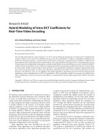
Most of the current day components (Figure 1-1) require more than
one single process to transform the raw material to the finished product. So
every single machine tool in this process cycle needs to maintain the high
degree of accuracy and precision in order to realize the end product with the
desired surface quality. Building such an ultra-precision machine with
absolutely no error tends to increase the cost of the machine which in return
increases the cost of the components too.
2
Figure 1-1: High Precision components
So in conjunction with the above mentioned precision needs, the
demand for developing ultra-precision machine tool to cater their
manufacturing are rapidly expanding. Improved design methodologies and
advanced materials technology has revolutionized machine tool industry
which is striving hard to achieve the sub-nanometric regime as mentioned by
Norio Taniguchi [1] who coined the term “Nano-technology” in late 1970s. He
studied the historical progress of the manufacturing technology and predicted
its future trends.
The machining accuracy was classified based on the accuracy
needs/level into a) normal machining, b) precision machining and c) ultra-
precision machining. As the years increment, the accuracy and repeatability
needs of the product gets stringent and complex to achieve. The current trend
in precision technology is defined by the trends in IC technology, information
display and storage, MEMS, bio-medical engineering and customer product
needs [2]. Currently sub-nanometric (<0.001µm) accuracy levels are required
in all the precision manufacturing industries. In order to achieve such stringent
levels of accuracy, a precise machine tool with closed-loop control system