Coupling effects of NaYF4Yb,Er upconversion nanoshells and au ag metallic nanoshells 1
Bạn đang xem bản rút gọn của tài liệu. Xem và tải ngay bản đầy đủ của tài liệu tại đây (392.91 KB, 23 trang )
1
Chapter 1 Introduction
1.1 Background
Nanostructured materials have significantly different characteristics
from their bulk counterparts.
1
Inorganic nanoparticles such as semiconductor
quantum dots, metallic nanoparticles, and lanthanide ions doped upconversion
nanoparticles have attracted interests due to their size- and shape-dependent
optical properties.
2,3
Recently, the combination of metallic nanostructures and
lanthanide ions doped upconversion nanostructures have gained a growing
interest due to their potential applications in bioimaging and photothermal
therapy of cancer cells.
4,5
The fluorescence of fluorophores, such as organic dyes or quantum,
dots was enhanced when they were located near metallic nanoparticles due to
the plasmonic effects.
6,7
The interactions of these fluorophores with metallic
nanoparticles have been extensively investigated.
8,9
Recently, the plasmonic
effects from the metallic nanoparticles have been proposed to enhance the
fluorescence of upconversion nanoparticles.
10
In this chapter, lanthanide ions doped upconversion nanoparticles,
metallic nanostructures, and their unique optical properties are discussed in
detail. The fluorescence coupled with the plasmonic effects is also discussed.
1.2 Upconversion
Upconversion (UC) commonly refers to a nonlinear optical processes
in which the sequential absorption of two or more incident photons leads to
2
the emission of a photon at a shorter wavelength than the excitation
wavelength.
11
For example, near infrared (NIR) lights can be converted into
visible lights via the UC process. This NIR-to-visible UC technique has
potential applications in three-dimensional (3D) displays,
12
white light-
emitting diodes (LED),
13
solar cells,
14
and bioimaging.
15
Successful synthesis of UC nanoparticles led to exploration of NIR-to-
visible bioimaging.
16,17,18
NIR lights as an excitation source can reduce
autofluorescence from biological specimens, improving signal-to-noise ratios
compared with ultraviolet (UV) lights commonly used in quantum dots,
conventional organic dye, or fluorescent proteins.
19
The NIR excitation source
has high penetration depth in biological specimens. For example, NIR lights
can penetrate as deep as a few to 10 cm into biological tissues, whereas UV
light can penetrate only 1-2 mm.
20
NIR excitation source can also minimize
photodamage to biological tissues as its energy is lower than the UV source.
1.2.1 UC mechanism
The UC mechanism commonly consists of excited state absorption
(ESA) and energy transfer upconversion (ETU).
21,22
Both mechanisms
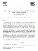
involve the sequential absorption of two or more photons (Fig. 1.1). In ESA
mechanism, a single dopant ion is excited from the ground state G to the first
exited state E1 by an incident photon (Fig. 1.1a). A second incident photon
promotes the excited ion from E1 to the higher excited state E2. UC emission
is produced when the excited ion returns to the ground state G from the exited
state E2.
3
Fig. 1.1
UC mechanisms: (a) Excited state absorption (ESA) and (b) energy
transfer upconversion (ETU). The dashed-dotted, dashed, and solid red lines
represent photon excitation, energy transfer, and emission processes,
respectively.
In contrast to ESA, ETU process involves non-radiative energy
transfers between two neighboring ions. In ETU process, the two neighboring
ions individually absorb a photon with same energy; thereby this ion is excited
from its ground state to the higher energy state E1 (Fig. 1.1b). Non-radiative
energy transfer process promotes one of the ions to the upper state E2 while
the other relaxes back to the ground state G. UC emission is produced when
the ion at energy state E2 returns to its ground state. The UC efficiency of an
ETU process is strongly influenced by the dopant ion concentration which
determines the average distance between the neighboring dopant ions. It is
important to note that photon avalance (PA) is the other UC mechanism based
on the sequential absorption of two or more photons. This mechanism is less
observed in UC process than the ESA and ETU mechanisms.
In the UC mechanism, at least two lower energy photons are required
to generate one higher energy photon. However, not all of the energy
absorbed is emitted as radiation. The excited ions can also undergo non-
4
radiative relaxation by transferring part of its energy to the host lattices as heat
when returning to the ground states. This undesirable non-radiative relaxation
mechanism always competes with the radiative transition in the UC process.
1.2.2 UC materials
UC materials commonly consist of a crystalline host material and
dopants. The dopant ions in the host provide characteristic UC luminescence
properties. Selection of host materials, dopants, and dopant concentration are
essential to obtain a highly efficient UC process.
A. Selection of host materials
Efficient hosts should have low phonon energy. Low phonon energy
host materials result in higher UC emission intensity since it can minimize the
non-radiative loss of electron transition from the excited states to the ground
states of lanthanide ions. This is because a larger number of phonons are
required for the non-radiative relaxation of excited electrons in the low
phonon energy hosts, leading to a lower probability of non-radiative
transitions. Heavy halide based materials such as chlorides, bromides, and
iodides have low phonon energy (less than 300 cm
-1
).
23
However, these
materials are undesirably hygroscopic. The fluorides (e.g. NaYF
4
and
NaGdF
4
) and oxides (e.g. Y
2
O
3
) exhibit low phonon energies, ~400 and ~600
cm
-1
, respectively. They have high chemical and thermal stability, thus they
are often used as a host of UC materials.
Host materials also require that its cations have ionic radii close to the
dopant ions in order to reduce lattice strain in the doped host. Hosts based on
5
Na
+
, Ca
2+
and Y
3+
cations are commonly used for UC materials as their cations
have ionic radii close to lanthanide dopant ions. The crystal structure of the
host material also significantly influences the optical properties.
24
For
example, Yb and Er ions doped hexagonal close-packed (hcp) NaYF
4
bulk
materials showed an emission about an order of magnitude higher than their
cubic phase counterparts.
25
This phase-dependent optical property is
attributed to the different crystal-fields around lanthanide ions in the hosts. To
date, NaYF
4
with hcp crystal structure is one of the most efficient hosts for
UC materials.
26
A. Dopants
Lanthanide (rare earth) ions are commonly used as a dopant for UC
materials. They exist in their most stable oxidation state as trivalent ions
(Ln
3+
). The 4f electrons in the lanthanide ions are shielded from the
surroundings by filled outer 5s
2
and 5p
6
orbitals. Therefore, the 4f energy
structures of lanthanide ions are not strongly affected by the host
environments. The electron transitions within the 4f energy states are Laporte-
forbidden, resulting in a low transition probability. Therefore, the lanthanide
elements themselves are not UC active. However, the 4f-4f transition would
occur when the trivalent lanthanide ions (Ln
3+
) are doped into a crystalline
host. The surrounding ligand ions generate a crystal field around the dopant
ions, increasing the 4f–4f transition probabilities of the lanthanide ions.
23
The ladder-like energy levels of the 4f states allow the lanthanide ions
for sequentially absorbing multiple photons with suitable energy to reach a
higher excited state. When the energy gaps between three or more subsequent
6
energy levels are very similar, the sequential excitation by a single
monochromatic light source to a higher excited state is possible since each
absorption step requires the same photon energy. Useful UC emission would
be produced when the excited ions return to its ground state.
In the UC materials, the lanthanide dopants may be categorized into
sensitizer and activator ions. A sensitizer is a donor of the energy, whereas an
activator is an acceptor of energy from the sensitizer and also an emitter of
radiation. The sensitizers can be excited by a photon, for example NIR, and
capable of transferring its energy to the neighboring activator ions.
27
Activator ions, after receiving the energy from the sensitizer ions,
subsequently emit photons with shorter wavelength than that of the excitation
wavelength in its relaxation. Lanthanide sensitizers commonly have a large
absorption cross-section at the excitation wavelengths to obtain high UC
efficiency. For example, Yb
3+
ion is widely used as the sensitizer in UC
materials due to its large absorption cross-section at 980-nm NIR excitation
wavelength. The absorption band of Yb
3+
ion located around 980 nm is
attributed to the
2
F
7/2
-
2
F
5/2
transition (Fig. 1.2). The
2
F
7/2
-
2
F
5/2
transition
energy gap of Yb
3+
ion is matched well with many 4f–4f transitions energy
gap of other lanthanide ions (e.g. Er
3+
, Tm
3+
, and Ho
3+
) which are commonly
used as the activator ions. This promotes efficient energy transfer from Yb
3+
ions to the other neighboring lanthanide activator ions in the UC materials.
7
Fig. 1.2 A schematic 4f energy-level diagram of Yb
3+
(sensitizer ion) and Er
3+
(activator ion).
Lanthanide activators have the energy levels to absorb the transfer of
energy from the excited sensitizer ions and then efficiently generate emission.
The energy difference between each excited level and its ground state in 4f
orbital of the activator ions should be close enough to photon absorption by
the sensitizer to facilitate the energy transfer steps.
Doping concentration of lanthanide ions is also essential since it affects
the distance between the dopant ions in the hosts, assuming a homogeneous
distribution. In principle, the absorption can be improved by increasing the
concentration of the lanthanide dopants in UC materials. However, there
appears an optimum doping concentration of the lanthanide ions to obtain high
UC efficiency. At a low doping concentration, UC emission intensity
increases with increasing the concentration of activator ions and would reach a
maximum at a certain concentration. Further increasing the concentration
8
would lead to a decrease of UC emission due to concentration quenching. For
example, the doping concentration of Er
3+
did not exceed 3 % in most Er
3+
doped UC materials.
24
However, the absorption by the dopant at such low
concentration is not sufficient. To increase the absorption, a higher
concentration of Yb
3+
sensitizer is codoped into the UC materials. The
concentration of Yb
3+
doped in UC materials is commonly 18 – 20 %. To
date, hcp phase NaYF
4
codoped with Yb
3+
and Er
3+
is one of the most efficient
NIR-to-visible UC materials.
26
The hcp NaYF
4
:20%Yb,2%Er is selected for
detailed study in this thesis.
1.2.3 Surface-dependent optical properties
In UC, the emission is produced through radiative transitions of
electrons from the excited states to the ground states in 4f orbitals of the
lanthanide ions. For example, under 980-nm NIR excitation, NaYF
4
:Yb,Er
nanoparticles produce the UC emission through the 4f-4f transitions of Er
3+
.
Optically active 4f electrons of lanthanide ions are shielded by filled
outer 5s
2
and 5p
6
orbitals, hence quantum confinement effects on electronic
states of these localized electrons are not expected for UC nanoparticles.
28
Therefore, the wavelength of UC emission peak is independent from the
particle size. As the size decreases, the ratio of surface-to-bulk atoms or ions
however increases, thus the surface effects on the optical properties of the
materials become more apparent compared to that of the bulk counterparts.
The local atomic environment of the surface atoms may be significantly
different from that of the interior atoms, accentuating the surface-dependent
optical properties.
29
For example, these surface atoms with fewer adjacent
9
coordination atoms and more unsaturated dangling bonds interact with the
surrounding environment. The UC nanoparticles are commonly rendered
dispersible using long chain organic surfactants (e.g. oleylamine and oleic
acid) to prevent aggregation. These surfactants however possess undesirably
high vibrational energy functional groups (typically~1500 cm
-1
and ~ 3000
cm
-1
)
30
, and may interact with the UC active surface ions of UC nanoparticles,
leading to undesirable non-radiative losses and decrease of the UC
emission.
25,31,32
The ratio of surface-to-bulk ions increases with decreasing
particle size, thus the emission of the UC nanoparticles is less than that of bulk
counterparts. For example, the emission intensity of UC nanoparticles with 8
– 30 nm in size was only 0.2 – 3 % of that of their bulk counterparts.
33
Further, the compositional segregation of dopant ions and OH impurities at the
particle surface may enhance the non-radiative mechanisms, decreasing the
UC emission intensity.
31,34
1.2.4 Surface passivation
To minimize the non-radiative losses, the UC active surface of UC
nanoparticles are commonly passivated by surface coating of low phonon
energy inorganic materials.
35,36
The surface coating would provide a barrier to
prevent undesired interactions between the UC active surface ions of UC
nanoparticles and high phonon energy environment such as surfactants and
solvents. The undoped host materials are usually used as the coating materials
due to low phonon energy and the similar lattice parameter as the doped UC
core materials. This would allow the shell deposition and epitaxial growth of
the shell on the core surface that may result in a better coverage and protection
10
of the doped nanoparticle core against the surrounding environment.
37
The
undoped hosts coated on the UC cores are commonly referred to as undoped
shells. The undoped shells would protect the surface of UC cores from high
phonon energy environments, preventing the undesirable non-radiative losses
and enhancing the UC emission intensity. It was shown that the UC emission
intensity of UC core/undoped shell nanoparticles increased with increasing
thickness of the undoped shell, with no further enhancement deserved when
the thickness exceeded 3 nm.
32
The 3-nm undoped shell was sufficiently thick
to prevent undesirable interactions with phonons of surfactant or other
molecules in the environment. The total UC emission enhancement of UC
cores/undoped shell increased by 15 times compared with that without the
intermediate undoped shell. Thus, the surface passivation by the undoped
shells is a powerful method to enhance the fluorescence of UC nanoparticles.
Recently, the plasmonic effects of metallic nanostructures have been proposed
for the fluorescence enhancement of UC nanoparticles,
10
which is discussed
in the following sections.
1.3 Metallic nanostructures
Metallic nanoparticles are of interests because of potential applications
in biomedical imaging,
38
photothermal therapy,
39,40
and fluorescence
enhancement.
41
Different from UC nanoparticles, the optical properties of
metallic nanoparticles arise from the interaction between an electromagnetic
wave (e.g. light) and the conduction electrons in the metal, leading to the
absorption and/or scattering at resonant wavelengths due to the excitation of
plasmon oscillations. For examples, the plasmon resonance at ~520 nm is
11
responsible for the ruby red colour displayed by the Au colloids. This optical
phenomenon has been used for centuries. The ruby red of stained glass
windows arises from Au nanoparticles, formed by the reduction of its metallic
ions in the glass-forming process. The optical properties of metallic
nanostructures may be tailored by controlling their composition, size, shape,
and structure. Au nanostructures are one of the most studied due to its good
biocompatibility, thermal, and chemical stability. Recently, Au nanostructures
have found interests due to their tunable localized surface plasmon resonance,
local field enhancement around the particle surface, and localized heating.
42
1.3.1 Localized surface plasmon resonance (LSPR)
Plasmon resonance is an optical phenomenon arising from collective
oscillations of free electrons against the fixed (lattice of) positive ions in a
metal induced by an electromagnetic wave (light).
43
The presence of an
external electric field, for example from incident light, causes displacements
of the free electrons in the metal. A restoring force from the positive ions in
the opposite direction to this displacement lead to the free electrons oscillate
backwards and forwards with respect to the fixed positive ions. The plasmon
frequency is determined by the restoring force and effective mass of the
electron.
42
The plasmon resonance caused by surface electrons are commonly
referred to as surface plasmon resonance.
44
For metallic nanoparticles with
dimensions smaller than the wavelength of incident light, a strong interaction
with the incident light through plasmon resonances that confined within the
particle surface is widely known as localized surface plasmon resonance
(LSPR) as shown in Fig. 1.3.
45
The LSPR causes enhanced optical extinction
12
(absorption + scattering) with a maximum at the plasmon resonant frequency.
The contribution of scattering relative to absorption increases as the particle
size increases. The theoretical frequency of LSPR is
/
√
3 for a metallic
nanosphere placed in vacuum, where
/
is the plasmon
frequency of a bulk metal, is the number density of conduction electrons,
is the dielectric constant of vacuum, is the charge of an electron, and
is
the effective mass of an electron.
Fig. 1.3 Schematic diagram of localized surface plasmon resonance (LSPR)
of metallic nanospheres.
45
The LSPR extinction peak of the metallic nanoparticles is dependent
on the size, shape, chemical composition, and surrounding medium. The
extinction peak red shifts with increasing particle size mainly due to
retardation effects.
46
This can be understood as the distance between regions
of oscillation-induced charges at opposite interfaces (surfaces) of the
nanoparticle increases with increasing size, leading to a smaller restoring force
and subsequent lower resonant frequency. Therefore, the LSPR extinction
peak shifts to longer wavelength with increasing particle size. For a sphere of
13
volume V and dielectric function
in the quasi-static limit, the
explicit expression for the extinction cross section
is
9
/
2
1.1
where
is dielectric constant of surrounding medium,
and
are real and
imaginary parts, respectively.
is a measure of the total effective area that
the EM fields perceive when interacting with the particle. It would reach a
maximum when the denominator in the above equation is minimum, a
condition where
= 2
. This shows the dependence of the LSPR
extinction peak on the surrounding dielectric medium. The details of
absorption and scattering cross sections for the metallic particles are discussed
in Appendix A.
1.3.2 Local field enhancement
Metallic particles (e.g. Au, Ag) are known to significantly enhance
electromagnetic field around them under incident light due to plasmon
resonance. The enhancement of the electromagnetic field intensities around
the metallic particles is produced due to the coupling between incident light
and collective oscillation of free electrons at the particle surface. The
displacements of the free electrons with respect to the fixed positive ions in
the metallic nanoparticles caused by an external electric field from the incident
light create charges at opposite surfaces, enhancing the local electric field
around the particles. The plasmon-induced electric field enhancement
depends on various parameters, such as wavelength, distance from the
14
particles, metallic element, surrounding medium, size, and shape of the
metallic particles.
47,48
Field intensity enhancement is commonly defined as
the intensity ratio between the electric fields around a metallic object under
incident fields and the incident fields in absence of the metallic object.
49
Figure 1.4 shows a schematic configuration of a metallic sphere under
an uniform incident electric field (
). The electric field intensity is
maximized at the direction 0, for most cases and the field intensity
enhancement (
|
|
|
|
⁄
) can be expressed as
|
|
|
|
12
2
1.2
where is electric field at a point of interest near the metallic particles in
an environment in which there exists a incident field
, and
are the
permittivity of the metal particle and the surrounding medium, respectively,
is a function of the frequency
of incident light, a is the radius of the metal
sphere which << of incident light, and r is the radius vector from the
particle center to a point of interest where the electric field is calculated.
Equation 1.2 shows the field intensity enhancement decreases with increasing
distance from the particle surface. For most cases, the field intensity
enhancement reaches a maximum at the plasmon resonant frequency.
49
The
local field enhancement around the metallic particles induced by their LSPR
has been utilized for a number of applications such as surface-enhanced
Raman spectroscopy (SERS) and fluorescence enhancement of the nearby
fluorophores.
50,51
15
Fig. 1.4 Schematic configuration of a metallic nanoparticle under uniform
incident electric field (E
o
).
1.3.3 Galvanic replacement reaction
Galvanic replacement reaction has been exploited as a powerful
method to synthesize hollow metallic nanostructures.
52
Galvanic replacement
reaction is driven by electrochemical potential difference between two metals,
with the higher potential metal serving as a cathode and the lower one as an
anode. The anode is defined as the electrode where oxidation occurs and the
cathode is the electrode where the reduction takes place. A conventional
example is Zn strip in a solution containing Cu
2+
ions. Since the Zn
2+
/Zn
standard reduction potential (-0.76 V) is more negative than that of Cu
2+
/Cu
(0.34 V), Zn is oxidized to Zn
2+
and Cu
2+
is reduced to Cu. This principle has
been extended to synthesis of hollow metallic nanostructure, which the metal
strip is replaced by metallic nanoparticles. For example, Ag nanoparticles
widely used as a sacrificial template in the galvanic replacement reaction,
reacted with AuCl
4
-
solution to form hollow Au or Au-Ag alloy
nanostructures.
53
The standard reduction potential of the AuCl
4
-
/Au pair (0.99
16
V) is more positive than that of the AgCl/Ag pair (0.22 V), thus the oxidation
of Ag nanoparticles by AuCl
4
-
would take place to form Au, AgCl, and HCl.
54
The galvanic replacement reaction between Ag and HAuCl
4
is expressed as:
3Ag
(s)
+ HAuCl
4
→ Au
(s)
+ 3AgCl
(s)
+ HCl
(aq)
. In this reaction, Au formed
from the reduction of AuCl
4
-
would deposit on Ag nanoparticles. Interior
cavity is formed when most of Ag solids have been oxidized, followed by the
formation of hollow Au or Au-Ag metallic nanoshells. The shape of the
metallic nanoshells depends on the shape of the sacrificial Ag templates.
Since the reaction takes place in the solution, the surrounding mediums (e.g.
solvents or surfactants) may be trapped in the interior cavity.
1.3.4 Metallic nanoshells
Hollow metallic nanoshells may have tunable optical properties and a
larger local field enhancement compared with that of their solid counterparts.
55
The LSPR extinction peak of hollow metallic nanoshells shifts to longer
wavelength than that of their solid counterparts. The extinction peak of the
nanoshells red shifts with decreasing shell thickness or increasing interior
cavity.
56
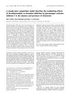
For example, the extinction peak of Au solid nanopsheres with 50
nm in diameter is calculated to be ~530 nm in water medium and their
corresponding Au nanoshells (diameter of 50 nm and shell thickness of 6 nm)
have the peak at ~624 nm (Fig. 1.5a).
The field intensity enhancement around the particle surface is larger
for Au nanoshells compared with that of their solid counterparts (Fig. 1.5b)
since the nanoshells showed a stronger coupling with the light due to the
plasmon hybridization of both sphere and cavity.
49
The calculated field
17
intensity enhancement at the (outer) particle surface is as high as ~250 times
for the Au nanoshells and ~34 times for the corresponding solid nanoparticles
at their respective extinction peaks. Therefore, the metallic nanoshells may be
a good candidate for the fluorescence enhancement of UC nanoparticles
compared with their solid counterparts. The field intensity enhancement
decreased with increasing the distance from the particle surface, consistent
with Eq. 1.2.
Fig. 1.5 (a) Calculated LSPR extinction spectra and (b) Calculated field
intensity enhancement of Au solid nanospheres (50 nm in diameter) and
spherical Au nanoshells (50 nm in diameter and 6 nm in shell thickness) in
water medium.
The LSPR extinction peak of metallic nanoshells is also more sensitive
to the change of surrounding medium than that of their corresponding solid
nanoparticles. LSPR sensitivity is commonly determined by the shift in
wavelength of the extinction peak for a corresponding change in medium
refractive index (∆/Δ) as measured in nm/refractive index unit (RIU). For
example, the LSPR sensitivity was 60 and 408 nm/RIU for solid Au
18
nanoparticles (diameter of 50 nm) and hollow Au nanoshells (diameter of 50
nm, shell thickness of 4.5 nm), respectively.
57
The optical sensitivity of
hollow metallic nanoshells can be explained by plasmon hybridization, as
discussed in Appendix B.
58,59
1.4 Plasmon-coupled fluorescence
Previous studies showed interactions between metallic particles and
fluorophores (e.g. organic dye, quantum dots) led to an increase or decrease in
the fluorescence of the fluorophores, depending on the relative magnitudes of
the fluorescence enhancement and quenching.
60,61
The interactions between
the metallic particles and the nearby fluorophores may be described as
follows: (1) enhanced light absorption of the nearby fluorophores due to field
enhancement induced by the LSPR of the metallic particles (2) enhanced
radiative emission of the fluorophores due to coupling to LSPR of the metallic
particles, and (3) metal-dipole interaction leads to non-radiative energy
transfer to the metal particles.
62
The first two terms lead to the fluorescence
enhancement, whereas the third term causes the fluorescence quenching. All
the three mechanisms are dependent on the distance of the fluorophores to the
metallic particles.
63
The enhanced field around the metallic particles can concentrate the
local excitation density, increasing light absorption of the nearby fluorophores
and enhancing the fluorescence. The radiative emission is influenced by the
balance of radiative and non-radiative decay rates. When the fluorophores are
too close or in direct contact with the metallic particles, non-radiative energy
transfer to the metallic particles would increase.
64,65
This non-radiative energy
19
transfer to the metallic particles leads to a decrease of the quantum yield
(quenching) of the nearby fluorophores.
For a fluorophore located close to a metallic particle, the enhancement
of excitation rate can be expressed as
66
∙
∙
1.3
where
and
is the excitation rate in the present and absence of
metallic particles, respectively,
is a unit vector pointing in direction of
transition dipole moment,
is incident electric field, and is electric
field at position of the fluorophore near the metallic particle. For electric field
intensity at the direction 0 (parallel direction to incident field
)
(Fig. 1.4), the excitation rate enhancement can be simplified to
|
|
|
|
1.4
Fluorescence intensity is proportional to the excitation rate and the
quantum yield.
67
Fluorescence enhancement of a fluorophore located near a
metallic particle is determined by the ratio between the fluorescence rate of the
fluorophore close to the metallic particle and that in absence of the metallic
particle. Therefore, the fluorescence enhancement (F) can be written as
|
|
|
|
1.5
20
where is the quantum yield of the fluorophore located near the metallic
particle and
is the intrinsic quantum yield (in absence the metallic particle).
Intrinsic quantum yield is defined as the ratio between the intrinsic radiative
decay rate (
) and the total intrinsic decay rate of the fluorophore (
). In the
absence of the metallic particle, the total intrinsic decay rate is given by the
sum of the intrinsic radiative and intrinsic non-radiative decay rates. The
intrinsic quantum yield can be expressed as:
⁄
⁄
,
where
is intrinsic non-radiative decay rate. For the fluorophores close to
metallic particles, the relative quantum yield may be expressed as
60
1
1.6
where
is the additional non-radiative decay due to the absorption by the
metallic particles. Since the radiative and non-radiative decay rates are
influenced by the distance from the fluorophores to the metallic particles,
68
the
quantum yield in the presence of metallic particles is also distance-dependent.
Theoretical calculations of the distance dependence of the non-radiative
energy transfer rate from a dye molecule to a metal nanoparticle followed a
distance dependence at large distances, whereas small deviations were
observed at shorter distances.
69
However, recent studies showed that the
resonance energy transfer rate is a
distance dependence.
64,70
21
1.5 Motivation and Objectives
The NIR-to-visible UC nanostructures have gained interests for a
number of potential applications as discussed earlier. Today, it remains a big
challenge to synthesize UC nanoparticles that have similar emission intensity
of their bulk counterparts since the nanoparticles have large surface area (large
number of surface atoms). For example, the emission intensity of UC
nanoparticles with 8 – 30 nm in size was only 0.2 – 3 % of that of their bulk
counterparts.
33
Therefore, it is necessary to find methods to enhance
fluorescence of UC nanostructures. UC nanoshells with interior cavity have
gained scientific interests due to their potential applications in bioimaging and
drug delivery. These nanoshells have even a larger number of surface atoms
than their solid counterparts due to their inner and outer surfaces. Hence, UC
nanoshells may be a good candidate for studying the effects of surface and the
UC fluorescence enhancement by surface coatings and plasmonic effects from
metallic particles. NaYF
4
:Yb,Er with hcp phase is one of the most efficient
UC materials.
26
Therefore, this material was selected to fabricate the UC
nanoshells in this thesis.
The fluorescence enhancement by plasmonic effects from metallic
particles has mainly involved the molecule dyes or quantum dots. Recently,
the plasmon-enhanced fluorescence has been applied to UC nanostructures.
To date, plasmonic effects on the surface coverage- and distance-dependent
fluorescence of UC nanostructures are not well-understood. Metallic
nanoparticles can efficiently generate heat in the presence of electromagnetic
radiation and subsequently transfer the heat to surrounding matrix. Most of
22
the previous studies have not considered the photothermal effects from the
metallic particles on the fluorescence properties of nearby UC nanostructures.
The local field enhancement near the particle surface may be larger for
the metallic nanoshells than their corresponding solid nanoparticles.
49
Thus,
the metallic nanoshells may be a good candidate to enhance the fluorescence
of UC nanostructures. In this thesis, Au-Ag metallic nanoshells were selected
as they have a strong plasmonic interaction with incident lights, leading to
local field enhancement.
To address the UC fluorescence issues, the effects of surface, surface
coatings, and plasmonic on the fluorescence of the UC nanoshells were
systematically studied. This thesis includes the followings:
1. Synthesis of NaYF
4
:Yb,Er UC nanoshells via thermal decomposition was
carried out. The microstructure and optical properties were investigated.
The effects of surface and surface coatings of undoped NaYF
4
on the
fluorescence of NaYF
4
:Yb,Er nanoshells were studied
2. Synthesis of Au-Ag metallic nanoshells was conducted via galvanic
replacement reaction of Ag templates with HAuCl
4
. The microstructure
and plasmonic properties of Au-Ag nanoshells were studied. The
transformation from the Ag templates to Au-Ag nanoshells was
systematically investigated.
3. The plasmonic effects of Au-Ag nanoshells on the fluorescence properties
of NaYF
4
:Yb,Er nanoshells were studied. The layer-by-layer assembly of
Au-Ag nanoshell layer/silica film/NaYF
4
:Yb,Er nanoshell layer was
prepared for different surface coverage % of Au-Ag nanoshell layer and
different thicknesses of silica film (to control the distance from the
23
NaYF
4
:Yb,Er nanoshell layer to the Au-Ag nanoshell layer). Thus, the
surface coverage- and distance-dependent fluorescence of the
NaYF
4
:Yb,Er nanoshells were investigated.
1.6 Outline of the thesis
The outline of this thesis is as follows:
1. Synthesis and characterization of NaYF
4
:Yb,Er nanoshells and the effects
of surface and surface coatings on the UC fluorescence.
2. Synthesis and characterization of Au-Ag metallic nanoshells. The
transformation from Ag templates to Au-Ag nanoshells via galvanic
replacement reaction.
3. The plasmonic effects of Au-Ag metallic nanoshells on the fluorescence
properties of NaYF
4
:Yb,Er nanoshells.
In the following chapters, the use of term “UC” often refers to NaYF
4
:Yb,Er.