Coupling effects of NaYF4Yb,Er upconversion nanoshells and au ag metallic nanoshells 5
Bạn đang xem bản rút gọn của tài liệu. Xem và tải ngay bản đầy đủ của tài liệu tại đây (1.3 MB, 18 trang )
85
Chapter 5 The plasmonic effects of Au-Ag nanoshells on fluorescence
properties of UC nanoshells
5.1 Introduction
The interactions of noble metals with fluorophores such as organic
dyes and quantum dots have been extensively investigated.
122,123
A previous
study reported the fluorescence of organic dyes was quenched when they were
located near Au nanoparticles.
68
However, other studies demonstrated the
fluorescence of organic dyes could be enhanced by nearby Au particles due to
the enhanced local field induced by the LSPR of Au particles.
124,125
The
fluorescence enhancement depended on the distance between the fluorophores
and metallic particles.
60,126
For a fluorophore sandwiched between two
individual Au nanoparticles, the fluorescence was dependent on the separation
distance between the two Au nanoparticles and polarization angle.
127
The
local field enhancement of metallic particles strongly depended on the
separation distance between the adjacent metallic particles.
128,129
Further
study on Au nanoparticles and quantum dots layer-by-layer assembled on a
substrate demonstrated that the Au nanoparticle concentration significantly
affected the fluorescence quenching efficiency.
65
Recently, the plasmonic effects of metallic particles have been utilized
to enhance the fluorescence of UC nanoparticles.
5,130
However, the effects of
concentration and distance of the metallic particles on fluorescence of UC
nanoparticles are not yet well-understood. It was reported that metallic
nanoparticles generated heat in the presence of electromagnetic radiation and
subsequent transferred the heat to the surrounding matrix.
131,132
In many of
86
these studies, the photothermal effects of metallic particles on the fluorescence
of nearby UC nanoparticles were not considered into account. Therefore, the
interactions of the metallic particles with the nearby UC nanoparticles
warranted further investigations.
Local field enhancement of metallic nanoshells may be larger than that
of their solid counterparts as discussed in Chapter 1. The LSPR peak of
metallic nanoshells can be tuned close to the excitation wavelength of a
fluorophore, creating the even greater near-field enhancement under the
excitation wavelength.
49
Therefore, the metallic nanoshells may be a good
candidate to enhance the fluorescence of UC nanostructures.
In this chapter, the plasmonic effects of Au-Ag nanoshells on the
fluorescence of UC nanoshells were investigated. Silica film was used as a
spacer to control the distance between the Au-Ag nanoshell layer and UC
nanoshell layer assembled on a substrate. The distance-dependent
fluorescence of the UC nanoshells was studied. The effects of Au-Ag
nanoshell concentration (coverage %) on the substrates were also investigated.
The results showed the fluorescence of the UC nanoshells was either enhanced
or quenched by Au-Ag nanoshells, depending on the silica film thickness and
the surface coverage % of the Au-Ag nanoshells. The local field enhancement
and photothermal effects of Au-Ag nanoshells on the surface coverage- and
distance-dependent fluorescence of the UC nanoshells are discussed.
87
5.2 Au-Ag nanoshell layer
Au-Ag nanoshells layer on a glass substrate was prepared using spin-
coating. The spin speed was 1500 rpm for 30 seconds for each cycle. The
larger Au-Ag nanoshells (which were synthesized from 43-nm Ag templates)
were used for UC fluorescence enhancement since they had a larger field
intensity enhancement around the nanoshell surface than their corresponding
smaller nanoshells (which were obtained from 20-nm Ag nanoparticles)
(Appendix Fig. E.1). Figure 5.1 shows the SEM images of Au-Ag nanoshells
deposited on the substrates using spin-coating for different number of coating
cycles. The Au-Ag nanoshells were randomly distributed to cover the
substrate surface and most of the nanoshells appeared to form a single layer on
the substrate. The nanoshells were closer with each other with increasing
number of coating cycles.
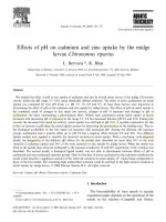
Fig. 5.1 SEM images of as-synthesized Au-Ag nanoshells spin-coated with
different number of coating cycles on the glass substrates: (a) 1 cycle, (b) 5
cycles, (c) 10 cycles, (d) 20 cycles, (e) 30 cycles, and (f) 40 cycles. The scale
bars for the images (a – f) are 1 m.
88
The SEM images showed the surface area of the substrates covered by
Au-Ag nanoshells increased with increasing number of spin-coating cycles. In
this thesis, the surface coverage was defined as the surface area occupied by
Au-Ag nanoshells divided by the total analyzed surface area. The average
surface coverage % of the Au-Ag nanoshell layer was calculated from the
SEM images using Java image processing and analysis program (ImageJ).
Figure 5.2a showed the calculated surface coverage % for different number of
spin-coating cycles. The surface coverage increased from 0 to 46% when the
spin-coatings increased from 0 to 40 cycles. Zero surface coverage % was
referred to the absence of Au-Ag nanoshells on the substrates. It was reported
that the ~20% coverage of Au particles on a glass slide showed surface
plasmon effects on the most part of fluorophore layer deposited on the Au
particle layer.
124
Figure 5.2b shows the LSPR extinction spectra of the Au-Ag nanoshell
layer with different surface coverage %. They had a similar extinction peak
wavelength at ~613 nm. However, the intensity of the extinction peak
increased with the surface coverage %, as more Au-Ag nanoshells deposited
on the substrate surface with increasing number of spin-coating cycles.
89
Fig. 5.2 (a) Surface coverage of Au-Ag nanoshell layer on the glass substrate
calculated from the SEM images using Java image processing and analysis
program (ImageJ). (b) LSPR extinction spectra of the Au-Ag nanoshell layer
with different surface coverage % normalized to that of the glass substrate.
5.3 Effects of surface coverage
The Au-Ag nanoshell layer with different surface coverage % on the
substrates was further coated with silica film using sputtering. Their
extinction peaks red shifted from ~613 nm to ~640 nm after coating with the
silica film since the refractive index of silica (n = 1.45) is higher than that of
air (n = 1.00), consistent with previous studies.
57,133
Further, as-synthesized
UC nanoshells (7-nm interior cavity/4-nm shell) were deposited on the silica
film-coated Au-Ag nanoshell layer to form an assembly of Au-Ag nanoshell
layer/silica film/UC nanoshell layer using the deposition method as discussed
in Chapter 2 (Fig. 2.2). Figure 5.3a shows an SEM image of the UC nanoshell
layer. The UC nanoshells were well-distributed and covered most of the
surface. The schematic for the cross-section of the assembly of Au-Ag
nanoshell layer/silica film/UC nanoshell layer on the substrate is shown in Fig.
90
5.3b. Here, the decahedral Au-Ag nanoshells were used since the Au-Ag
nanoshells mainly consisted of decahedral shape as discussed earlier (Chapter
4). In the schematic, the decahedral Au-Ag nanoshells lying down on the
substrate were
viewed from side of the nanoshells. This assembly was used to
study the plasmonic effects of Au-Ag nanoshells on the fluorescence of UC
nanoshells under 980-nm NIR laser.
Fig. 5.3 (a) SEM image of the UC nanoshell layer. (b) Schematic for the
cross-section of the assembly decahedral Au-Ag nanoshell layer/silica
film/UC nanoshell layer on the glass substrate, which under 980-nm NIR
laser. In the schematic, the decahedral Au-Ag nanoshells lying down on the
substrate were
viewed from side of the nanoshells.
Figure 5.4 shows the UC fluorescence spectra of the assembly of Au-
Ag nanoshell layer/silica film/UC nanoshell layer for different surface
coverage % of the Au-Ag nanoshell layer. Zero surface coverage % was
referred to as the assembly without Au-Ag nanoshell layer (assembly of silica
film/UC nanoshell layer). The UC fluorescence intensity was enhanced for
the assembly in the presence of Au-Ag nanoshell layer at low surface coverage
% as compared with that in the absence of Au-Ag nanoshell layer. The UC
91
fluorescence intensity initially increased with increasing Au-Ag surface
coverage %. When the surface coverage of Au-Ag nanoshell layer was higher
than ~22%, the UC fluorescence intensity decreased with further increasing
the surface coverage %. Further, the intensity ratio of two green emission
peaks changed with increasing the surface coverage of Au-Ag nanoshell layer.
This may be attributed to thermal effects from Au-Ag nanoshells, which is
discussed in Section 5.3.2.
Fig. 5.4 UC fluorescence spectra of Au-Ag nanoshell layer/30-nm silica
film/UC nanoshell layer for different surface coverage % of Au-Ag nanoshell
layer under 980-nm NIR excitation. Zero surface coverage % was referred to
as the assembly without Au-Ag nanoshell layer (assembly of silica film/UC
nanoshell layer).
Relative fluorescence factor (RFF) is defined as the total integrated UC
emission intensity of the assembly of Au-Ag nanoshell layer/silica film/UC
nanoshell layer normalized by that of the assembly of silica film/UC nanoshell
(zero Au-Ag surface coverage %). When the RFF is higher than unity, it
92
indicates a fluorescence enhancement. A fluorescence quenching is indicated
when the RFF is lower than unity. Figure 5.5 shows the RFF calculated from
the UC fluorescence spectra shown in Fig. 5.4. The RFF was higher than
unity for the assembly in the presence of Au-Ag nanoshell layer at low surface
coverage % (region I), indicating the UC fluorescence enhancement. The RFF
increased with increasing the Au-Ag surface coverage % and reached a
maximum value of ~2.5 at surface coverage of ~22%. The RFF decreased
with further increasing the surface coverage from ~22% to ~46% (region II).
The RFF was observed to be ~1.0 at 46% surface coverage of Au-Ag
nanoshell layer.
Fig. 5.5 (a) Relative fluorescence factor (RFF) at different surface coverage
% of Au-Ag nanoshell layer. RFF is defined as the total integrated UC
emission intensity of the assembly of Au-Ag nanoshell layer/silica film/UC
nanoshell layer normalized by that of the assembly of silica film/UC
nanoshells.
93
5.3.1 Local field enhancement
The increase of surface coverage of Au-Ag nanoshell layer would lead
to an increase in the density of Au-Ag nanoshells on the substrates and
decrease of separation distance between two adjacent Au-Ag nanoshells
(Appendix Fig. E.2). This would allow for a greater interaction between the
adjacent Au-Ag nanoshells, leading to a larger local field enhancement.
127
Figure 5.6a, b shows the calculated field intensity enhancement (
|
|
|
|
⁄
)
of two adjacent Au-Ag nanoshells coated by silica film at the plasmon
resonant and 980-nm NIR wavelengths, respectively, for different separation
distances of the two Au-Ag nanoshells. The field intensity enhancement was
calculated at the surface of silica film (the insets of Fig. 5.6a, b).
The calculation of field intensity enhancement was performed using
the CST studio suite 2012 simulation software, frequency domain solver based
on the finite element method (FEM). The setting condition is described as
follows. The boundary condition for X and Y axis (parallel to the surface of
glass substrate) was periodic and the Z axis (perpendicular to the surface of
glass substrate) was open. The plane wave propagation (k) was in direction of
45
o
to the substrate surface. Drude model was used for the refractive index of
Au and Ag. In this simulation, we assumed the Au-Ag nanoshell formed an
Au-Ag alloy and the interior cavity was filled with toluene which used as a
solvent in the synthesis of Au-Ag nanoshells, as discussed in Chapter 4. The
composition of Au and Ag was measured to be 65% and 35%, respectively.
The dielectric function of the Au-Ag alloy was calculated from the dielectric
function of Au and Ag based on their respective mole fraction.
112,134
94
Fig. 5.6 The calculated field intensity enhancement (|E|
2
/|E
o
|
2
) for different
separation distance of two Au-Ag nanoshells at (a) the plasmon resonant and
(b) 980-nm NIR wavelengths. The field intensity enhancement was calculated
at the surface of the silica film (30 nm in thickness) as shown by the insets of
(a) and (b). The plane wave propagation (k) was in the direction of 45
o
to the
glass surface. The decahedral Au-Ag nanoshells (~39-nm interior cavity/~6-
nm shell) were used in the calculation. The decahedral Au-Ag nanoshells
lying down on the substrate were viewed from side of the nanoshells. It
assumed the interior cavity of the nanoshells was filled with toluene, which
was used as a solvent in synthesis of the nanoshells as discussed in Chapter 4.
The calculations showed the field intensity enhancement at the
plasmon resonant and UC excitation (980 nm) wavelengths increased when
the separation distance of the two Au-Ag nanoshells decreased from 90 nm to
2 nm. The increase of the field intensity may be attributed to the increased
coupling between the two adjacent Au-Ag nanoshells with decreasing their
separation distance.
135
This suggested higher surface coverage % of Au-Ag
nanoshell layer would result in a higher local field enhancement since the
separation distance between two adjacent Au-Ag nanoshells decreased with
increasing the Au-Ag surface coverage. Therefore, the increase of RFF in the
region I (Fig. 5.5) could be associated to the increase of local field intensity.
95
When the surface coverage was higher than 22% (the region II), the RFF
decreased with increasing the Au-Ag surface coverage %, despite the increase
of local field intensity enhancement as predicted by Fig. 5.6. The decrease of
RFF in the region II could be attributed to other factors that quench the UC
fluorescence, which are discussed in the following section.
5.3.2 Thermal effects
Previous studies showed metallic particles could efficiently generate
heat under electromagnetic radiation.
136,137
The amount of generated heat
increased with the number of metallic particles. The heat would transfer from
the metallic particles to surrounding matrix, increasing the temperature of the
surrounding matrix, such as silica film and UC nanoshells in our present study.
It was also reported the fluorescence emission of UC nanoparticles was
quenched with increasing temperature.
138
Figure 5.7a shows two green emission peaks of UC spectra for the
assemblies of Au-Ag nanoshell layer/silica film/UC nanoshell layer and silica
film/UC nanoshell under 980-nm NIR excitation. These two emission peaks,
~525 nm and ~545 nm were attributed to
2
H
11/2
-
4
I
15/2
and
4
S
3/2
-
4
I
15/2
transitions of Er
3+
, respectively (Appendix Fig. F.1). Previous studies reported
the intensity ratio of
2
H
11/2
-
4
I
15/2
to
4
S
3/2
-
4
I
15/2
transitions (R
HS
) increased with
increasing temperature.
139,140
In this thesis, the R
HS
of UC nanoshells
increased for the assembly of Au-Ag nanoshell layer/silica film/UC nanoshell
layer as compared with the silica film/UC nanoshell layer under the 980-nm
NIR irradiation. This suggested that the temperature of UC nanoshells in the
assembly with Au-Ag nanoshell layer increased compared with the assembly
96
with no Au-Ag nanoshell layer. For the UC assembly with Au-Ag nanoshell
layer, the LSPR of the Au-Ag nanoshells that coupled with emitted lights from
the UC nanoshells or 980-nm NIR lights from the excitation laser would
generate heat. Since the 980-nm excitation light from the laser was much
stronger than the emitted light from UC nanoshells, therefore, the heat may be
mainly generated from the absorption of 980-nm NIR light by Au-Ag
nanoshells. These generated heat could transfer to the silica thin film and
subsequently the UC nanoshells, increasing the temperature of UC nanoshells.
The R
HS
decreased when Au-Ag nanoshell layer were removed from the
assembly (silica film/UC nanoshell layer) as shown in Fig. 5.7a, indicating the
decrease in temperature of the UC nanoshells. The temperature of the UC
nanoshells in the assembly was calculated from the R
HS
using by Boltzmann
law, which can be expressed as
I
/
/
I
/
/
∆
5.1
ln
ln
∆
1
5.2
where I (
2
H
11/2
–
4
I
15/2
) and I (
2
S
3/2
–
4
I
15/2
) are emission intensity due to
transitions of
2
H
11/2
–
4
I
15/2
and
2
S
3/2
–
4
I
15/2
, respectively, ∆ is energy gap
between
2
H
11/2
and
2
S
3/2
energy levels,
is Boltzmann constant, C is a
constant, and T is absolute temperature. The detailed calculation is shown in
Appendix F.
97
Fig. 5.7 (a) UC emission spectra of the assemblies of Au-Ag nanoshell
layer/30-nm silica film/UC nanoshell layer (Au-Ag surface coverage of 46%)
and silica film/UC nanoshell layer at green region. (b) The calculated
temperature of UC nanoshells in the assembly of Au-Ag nanoshell layer/30-
nm silica film/UC nanoshell layer for different surface coverage % of Au-Ag
nanoshell layer.
Figure 5.7b shows the calculated temperature of UC nanoshells in the
assembly increased as the surface coverage % of Au-Ag nanoshell layer
increased. This suggested more heat was generated with increasing number of
Au-Ag nanoshells. This heat would transfer from Au-Ag nanoshells to the UC
nanoshells, increasing the temperature of UC nanoshells. It was reported that
UC fluorescence intensity of Er
3+
doped chalcogenide glasses (Ga
2
S
3
: La
2
O
3
)
decreased with increasing temperature from 23
o
C to 200
o
C due to non-
radiative losses.
141
This temperature-dependent UC fluorescence was further
confirmed using hcp NaYF
4
:Yb,Er UC nanoparticles.
138,142
Figure 5.7b
demonstrates that a sharp temperature increase was observed when the surface
coverage of Au-Ag nanoshells was higher than 22%. This sharp increase in
temperature could contribute to a significant fluorescence quenching of the
98
UC nanoshells, decreasing the UC emission intensity. This explains the
decrease of RFF when the Au-Ag surface coverage was higher than 22% (the
region II) as shown in Fig 5.5. At these regions, the RFF decreased with
increasing the Au-Ag surface coverage %. When the surface coverage
increased to 46%, the RFF decreased to ~1.0. This result suggested the
fluorescence quenching by photothermal effects and the fluorescence
enhancement by local field enhancement could occur, depending on the
coverage of metallic nanoshells.
5.4 Distance-dependent UC fluorescence
To study the effects of distance between Au-Ag nanoshell layer and
UC nanoshell layer on the UC fluorescence, Au-Ag nanoshell layer on the
substrate was coated with different thicknesses of silica films (5 – 180 nm) to
form silica film-coated Au-Ag nanoshell layer (Appendix Fig. G.1), followed
by the deposition of UC nanoshells. The silica film was used as a spacer
between the UC nanoshell layer and Au-Ag nanoshell layer. Therefore, the
distance between the UC nanoshell layer and Au-Ag nanoshell layer was
controlled by thickness of the silica film. In this study, Au-Ag nanoshell layer
with surface coverage ~22% was used since it produced a maximum UC
fluorescence enhancement as discussed earlier. The distance-dependent UC
fluorescence of the UC nanoshells in the assembly was then investigated under
980-nm NIR excitation.
Figure 5.8a shows the RFF of the assembly of Au-Ag nanoshell
layer/silica film/UC nanoshell layer for different thicknesses of silica film.
The result showed the RFF was lower than unity for the assembly with silica
99
film smaller than 5 nm. This indicated the UC fluorescence was quenched
when the silica thickness was less than 5 nm, even though the calculated field
intensity enhancement of Au-Ag nanoshells was high at this region (Fig. 5.8b,
c). A possible explanation for this result is given as follows. Previous reports
showed the fluorescence of fluorophores (e.g. organic dyes and quantum dots)
was quenched when they were too close or in direct contact with metallic
nanoparticles due to non-radiative energy transfer from the fluorophores to the
metallic nanoparticles.
143,144
The non-radiative energy transfer from the
fluorophores to the metallic particles at short separation distance is commonly
associated to fluorescence resonance energy transfer (FRET). The quenching
efficiency of the fluorophores to metallic particles sharply increased as the
distance from the fluorophores to the metallic particles decreased.
65,69
However, there was almost no fluorescence quenching to the metallic
nanoparticles when the distance increased to ~30 nm.
70
By using the similar
explanation, in our present study, when silica film thickness < 5 nm, the UC
nanoshells may be too close with Au-Ag nanoshells to allow non-radiative
losses from the excited UC nanoshells to Au-Ag nanoshells, leading to the UC
fluorescence quenching. The result suggested, at these distances, the
magnitude of fluorescence quenching due to non-radiative losses to Au-Ag
nanoshells were probably greater than the magnitude of fluorescence
enhancement caused by the local field intensity enhancement of Au-Ag
nanoshells, leading to a RFF lower than unity.
When the silica thickness increased to 5 nm, the RFF increased to 1.0.
This could be the distance whereby the fluorescence enhancement by
enhanced local field intensity and the quenching due to the non-radiative
100
losses equally contributed, resulting in no change in the total fluorescence
intensity. When the silica thickness increased from 5 to 30 nm, the RFF
increased and reached a maximum value of ~2.5 at 30-nm silica thickness. At
these silica thicknesses, the magnitude of UC fluorescence enhancement due
to the enhanced local field intensity by Au-Ag nanoshell layer was probably
larger than the magnitude of fluorescence quenching due to the non-radiative
losses, leading to fluorescence enhancement. Further increasing the silica
thickness from 30 – 180 nm, the RFF decreased toward unity (unenhanced
value) as the local field intensity enhancement decreased with increasing
distance from the surface of Au-Ag nanoshells and toward unenhanced field
intensity (Fig. 5.8b, c). When the UC nanoshells were far from the Au-Ag
nanoshells separated by thick silica film (> 120 nm), the UC fluorescence
intensity of the assembly of Au-Ag nanoshell layer/silica film/UC nanoshell
layer was similar to that of the assembly of silica film/UC nanoshell layer. A
3D contour plot of the field intensity enhancement for Au-Ag nanoshells on
the glass substrates is shown in Fig. 5.8d.
The above results indicated that there existed an optimized coverage of
metallic nanoshells and the separation distance between metallic nanoshells
and UC nanoshells, where the effects of local field enhancement predominated
the non-radiative effects due to the metallic shell’s coupling with UC
nanoshells. The fluorescence enhancement or quenching would depend on the
complicated competitions among these factors.
101
Fig. 5.8 (a) Relative fluorescence factor (RFF) of the assembly of Au-Ag
nanoshell layer/silica film/UC nanoshell layer with different thicknesses of
silica film. Calculated field intensity enhancement (|E|
2
̸ |E
o
|
2
) for Au-Ag
nanoshells coated with different thicknesses of silica films at (b) the plasmon
resonant and (c) 980-nm NIR wavelengths. The field intensity enhancement
was calculated using the CST studio suite 2012 simulation software at the
silica surface (the insets of (b) and (c)), where the UC nanoshells were
deposited on. The setting condition was similar with that discussed earlier.
(d) The 3D
contour plot of the field intensity enhancement at the plasmon
resonant wavelength for Au-Ag nanoshell on the glass substrate.
The color
scale is logarithmic.
102
5.5 Summary
This study demonstrated that the UC emission of the UC nanoshells
can be either enhanced or quenched by Au-Ag nanoshells, depending on the
silica film thickness and the surface coverage % of the Au-Ag nanoshells.
When the silica thickness was fixed, for low Au-Ag surface coverage (< 22%),
the UC fluorescence intensity increased with increasing surface coverage %
due to the increase of local field intensity enhancement of Au-Ag nanoshells.
When the surface coverage was higher than 22%, the UC fluorescence
intensity decreased with increasing surface coverage % due to the thermal
effects of Au-Ag nanoshells. When the surface coverage % of Au-Ag
nanoshell layer was fixed, the UC fluorescence quenching, enhancement, and
subsequent unenhanced UC fluorescence intensity were found to be related to
increasing thickness of silica film.