Design and modeling of wireless link for biomedical implantable applications
Bạn đang xem bản rút gọn của tài liệu. Xem và tải ngay bản đầy đủ của tài liệu tại đây (2.88 MB, 124 trang )
DESIGN AND MODELING OF WIRELESS
LINKS FOR BIOMEDICAL IMPLANTABLE
APPLICATIONS
DUAN ZHU
(B.S. Huazhong Uni. of Sci. & Tech., 2009)
A THESIS SUBMITTED
FOR THE DEGREE OF DOCTOR OF
PHILOSOPHY
DEPARTMENT OF ELECTRICAL AND
COMPUTER ENGINEERING
NATIONAL UNIVERSITY OF SINGAPORE
2013
i
ii
Abstract
Implantable microsystems have attracted attention from researchers all
around the world, due to the fact that the miniaturization of electronics
systems and reduction of power consumption of chips make the actual
implantation of extremely complex microsystems possible.
For these microsystems, the wireless communication link is essential to
ensure robust communications between an implanted device and an external
monitoring apparatus. For most cases, the communication link is composed of
power link and data link. The power link consists of two closely spaced coils
intended for wireless power transfer based on inductive coupling. The data
link is realized by either coupling coils for near-field communications or a pair
of antennas for far-field purposes. This work presents the optimization method
of rectangular coils for maximum power transfer efficiency; proposes the first
differentially fed dual-band implantable antenna for data transfer in neural
recording system and evaluates the performance of a novel differential antenna
in MICS and ISM bands for dual-mode operation. Also, the interference issues
between the power link and data link are examined as well.
iii
Acknowledgements
Both the thesis and the author have benefitted a great deal from many
people over the past four years. Without their consistent help and
encouragement, this work cannot be achievable.
Foremost, I would like to give my special thanks to my kind supervisor,
Prof. Yong-Xin Guo, for introducing me into such a wonderful and
meaningful area of Microwave and Radio Frequency intended for biomedical
implantable applications. His prospective insight at the scientific frontier
really helped me a lot in carrying out the research work. Thank you for your
help all along the way.
Secondly, I would like to give my hearty thanks to my co-supervisor Prof.
Dim-Lee Kwong and my group leader Dr. Minkyu Je from Institute of
Microelectronics (IME), A*STAR. Ever since I joined the group in IME, they
have helped me a lot in understanding the bio-implants from system point of
view. I am really grateful for their kind help offered.
Thirdly, I would like to thank all the fellow researchers for their sincere
help: Dr. Hui Chu, Dr. Meysam Sabahi Al-shoara, Dr. Yujian Chen, Dr.
Zhengguo Liu, Dr. Xinyi Tang, Changrong Liu, Dr. Lei Wang, Rangarajan
Jegadeesan, Dr. Xiaoyue Bao, Lijie Xu, Hucheng Sun, and Yunshen Long.
The useful technical discussions with them have been extremely beneficial in
completing my research work.
Lastly, I would like to thank my beloved parents. Apart from my own
research interests, their deep understanding and endless support for me has
also been an important source of motivation for me in the pursuit of the
scientific path. Thanks a lot for your caring and love.
iv
List of Publications
[1] Z. Duan, Y.X. Guo, M. Je, and D.L. Kwong, “Design and in vitro
test of differentially fed dual-band implantable antenna operating at
MICS and ISM bands”, IEEE Trans. Antennas Propag., major
revision.
[2] Z. Duan, Y.X. Guo, R.F. Xue, M. Je, and D.L. Kwong,
“Differentially-fed dual-band implantable antenna for biomedical
applications”, IEEE Trans. Antennas Propag., vol. 60, no.12, pp.
5587-5595, Dec 2012.
[3] Z. Duan, Y.X. Guo, and D.L. Kwong, “Rectangular coils
optimization for wireless power transmission”, Radio Sci., vol. 47,
RS3012, Jun. 2012.
[4] K. Cheng, X. Zou, J. H. Cheong, R F. Xue, Z. Chen, L. Yao, H K.
Cha, S. J. Cheng, P. Li, L. Liu, L. Andia, C. K. Ho, M Y. Cheng, Z.
Duan, R. Rajkumar, Y. Zheng, W. L. Goh, Y. Guo, G. Dawe, W T.
Park, and M. Je, “100-channel wireless neural recording system with
54-Mb/s data link and 40%-efficiency power link,” in Proc. IEEE
Asian Solid State Circuits Conference (A-SSCC) Dig. Tech. Papers,
Nov. 2012, pp.185–188.
[5] Z. Duan, Y.X. Guo, R.F. Xue, M. Je, and D.L. Kwong,
“Investigation of the mutual effect between power link and data link
for biomedical applications”, IEEE International Symposium on
Radio-Frequency Integration Technology (RFIT), Singapore,
Singapore, Nov. 21-23, 2012, pp. 219-221.
[6] Z. Duan, Y.X. Guo, “Rectangular coils modeling for inductive links
in implantable biomedical devices”, IEEE International Symposium
on Antennas and Propagation (APSURSI), Spokane, Washington,
USA, Jul. 3-8, 2011, pp. 388-391.
[7] Y.X. Guo, Z. Duan, R. Jegadeesan, “Inductive wireless power
transmission for implantable devices”, 2011 International Workshop
on Antenna Technology (iWAT), Mar. 7-9, Hong Kong, 2011, pp.
445-448.
v
Table of Contents
Declaration i
Abstract ii
Acknowledgements iii
List of Publications iv
Table of Contents v
List of Tables viii
List of Figures ix
List of Symbols xiii
List of Acronyms xv
Chapter 1 Introduction 1
1.1 Background for Biomedical Telemetry System 1
1.2 Frequency Bands, Tissue Properties and Safety Issues 5
1.2.1 Frequency Bands for Biomedical Telemetry 5
1.2.2 Tissue Properties and Human Models 6
1.2.3 Safety Issues 9
1.3 Original Contributions and Thesis Outlook 10
Chapter 2 Wireless Power Transfer for Rectangular Coils 13
2.1 Introduction 13
2.2 Power Efficiency 15
2.2.1 Power Efficiency 15
2.2.2 Effect of C
1
on the Inductive Link 18
2.2.3 Effect of R
L
on the Inductive Link 18
2.2.4 Effect of R
src
on the Inductive Link 19
2.3 Modeling 19
2.3.1 Self Inductance 20
vi
2.3.2 Mutual Inductance 22
2.3.3 Serial Resistance 24
2.3.4 Parasitic Capacitance 24
2.3.5 Efficiency Calculation 25
2.4 Design Procedure 25
2.4.1 Step 1: Applying Design Constraints 26
2.4.2 Step 2: Initial Values 27
2.4.3 Step 3: Optimizing Secondary Coil 28
2.4.4 Step 4: Optimizing Primary Coil 29
2.4.5 Step 5: Optimized Design 31
2.5 Measured Performance 31
2.6 Conclusion 33
Chapter 3 A Differentially Fed Dual Band Implantable Antenna Operating
near MICS Band for Wireless Neural Recording Applications 35
3.1 Introduction 35
3.2 Antenna Design and Mixed-mode Theory 36
3.2.1 Antenna Design 36
3.2.2 Differential Reflection Coefficient Characterization 38
3.3 Simulation Environment, Results and Operating Principle 40
3.3.1 Simulation Environment 40
3.3.2 Operating Principle 42
3.3.3 Three-layer Tissue 44
3.3.4 SAR Distribution 47
3.4 Measurement Results 48
3.5 Communication Link 51
3.6 Co-testing with the Circuits in Minced Pork 55
3.7 Conclusion 58
vii
Chapter 4 A Differentially Fed Dual Band Implantable Antenna Operating at
MICS Band and ISM Band 60
4.1 Introduction 60
4.2 Planar Antenna Design 62
4.2.1 Simulation Environment 62
4.2.2 Planar Antenna Design and Simulation Results 64
4.2.3 Conformal Capsule Design and Simulation Results 68
4.3 SAR and Radiation 73
4.4 Coating and In Vitro Measurement 76
4.4.1 Coating Process 76
4.4.2 In Vitro Measurement 78
4.5 Conclusion 80
Chapter 5 Interference Evaluation for Power and Data Links 81
5.1 Introduction 81
5.2 Overview of the Communication Link 82
5.3 Investigation of Power and Data links and the Interference 84
5.3.1 Power Link 84
5.3.2 Data Link 85
5.3.3 Interference 85
Chapter 6 Conclusion 93
6.1 Thesis Assessment 93
6.2 Future Work 96
BIBLIOGRAPHY 97
viii
List of Tables
Table 1-1
Table 1-2
Table 1-3
Table 2-1
Table 2-2
Table 2-3
Table 3-1
Table 3-2
Table 3-3
Table 3-4
Table 4-1
Table 4-2
Table 4-3
Table 4-4
Table 5-1
Common frequency bands for data communication for
biomedical application 5
Frequency bands for ISM band 6
CST human models 9
Design constraints 27
Geometrical parameters of optimized coils 31
Comparison results from three approaches of optimized coils
33
Geometrical dimension of proposed antenna 38
Dielectric properties of tissues 41
Maximum SAR values and maximum allowed input power
47
Parameters of the link budget 54
Dielectric properties of tissues at MICS and ISM band 63
Geometrical dimension of proposed planar antenna 65
Geometrical dimension of proposed flexible antenna 70
SAR values of proposed antenna (Input power: 1 W) 73
Coupling strength between D
ex
and D
in
with the power link
at 403 MHz 89
ix
List of Figures
Figure 1-1
Figure 1-2
Figure 1-3
Figure 1-4
Figure 1-5
Figure 2-1
Figure 2-2
Figure 2-3
Figure 2-4
Figure 2-5
Figure 2-6
Figure 2-7
Figure 2-8
Figure 2-9
Interconnection of WBAN, WPAN, WLAN and WMAN
[12]. 2
(a) Single inductive link used in the power and data transfer
system [14] (b) The block diagram of a neuroprosthetic
system with multiple links [16]. 3
The block diagram of an implantable prosthetic system [23].
4
Relative permittivity and conductivity of (a) skin-dry (b) fat
(c) muscle [44]. 8
Various human models which can be used in CST
simulation. 9
The equivalent circuit schematic of wirelessly coupled
system with lumped elements. 15
(a) The original schematic for inductive link without the IC
part. (b) The schematic after we do a parallel-to-series
conversion. 16
Geometrical parameters of a rectangular spiral coil. 20
Mutual inductance between the primary coil and secondary
coil, and the arrow in the traces indicates the direction of
current. 22
Equivalent transformation. 25
Flowchart for the design procedure 26
Optimize the r ratio and w of coil while assuming the
dimensions for the secondary and primary coil are the same.
(a) Efficiency versus r and w. (b) Efficiency versus r
assuming w = 150 mm. 28
Optimize the outer dimensions l
p1
and w
1
of primary coil. (a)
Efficiency versus l
p1
and w. (b) Efficiency versus l
p1
assuming w
1
= 250 mm. 30
Fabricated coupling coils with supporting and connecting
materials. 31
x
Figure 2-10
Figure 3-1
Figure 3-2
Figure 3-3
Figure 3-4
Figure 3-5
Figure 3-6
Figure 3-7
Figure 3-8
Figure 3-9
Figure 3-10
Figure 3-11
Figure 3-12
Figure 3-13
Figure 3-14
Measurement setup for the coupling coils. 32
Geometry of the proposed dual-band differentially-fed
antenna. 37
Simple schematic for conventional single-ended port to
differential port conversion. 38
Simplified geometries for the one-layer tissue model (not in
scale). 41
Electric current paths of the proposed dual-band
differentially-fed antenna. 42
Antenna design variations to validate the operating principle.
42
Odd mode reflection coefficient comparison of the original
design and three modified designs for validating the
operating principle. 43
Simplified geometries for the three-layer tissue models, with
antenna implanted (a) in the middle of skin layer (b) between
skin and fat layer (c) in the middle of fat layer (d) in the
middle of muscle layer. 45
Comparison of odd mode reflection coefficient in different
tissue models and in various positions. 46
SAR distribution of proposed antenna at the operating
frequency of (a) 423 MHz, y-z plane (b) 532 MHz, y-z plane
(input power for each port: 6.29 μW). 48
Top and bottom views of the fabricated implantable antenna.
49
Measurement setup for the implanted antenna 50
Simulation and measurement results comparison of odd
mode reflection coefficient for the proposed antenna in air
and in liquid tissue. 50
Geometry of the external antenna. 51
(a) Simulation setup for characterizing the communication
link (length of antenna is not in scale). (b) S parameters of
the antenna pair. 52
xi
Figure 3-15
Figure 3-16
Figure 3-17
Figure 3-18
Figure 3-19
Figure 3-20
Figure 3-21
Figure 4-1
Figure 4-2
Figure 4-3
Figure 4-4
Figure 4-5
Figure 4-6
Figure 4-7
Figure 4-8
Figure 4-9
Figure 4-10
Figure 4-11
Figure 4-12
Variation of |S
21
| and link margin with respect to the distance
between two antennas. 55
System overview of the co-testing platform. 55
Communication link overview. 56
Block diagram of the proposed burst-mode injection-locked
FSK transmitter [76]. 56
Screen snapshot of output power of the transmitter. 57
Screen snapshot of received power by the external dipole. 57
Data plot of the transmitted power and received power. 58
The geometry of the proposed planar antenna. 64
(a) Simulation setup in HFSS and CST for one skin layer
model (not in scale). (b) Simulation setup in CST for chest
and shoulder implantation. 66
Comparison of differential reflection coefficient of planar
antenna for different simulation setups. 67
The conceptual application of the flexible antenna in a
capsule. 69
Geometry of the proposed flexible antenna and the
simulation setup for CST stomach implantation. 69
Geometrical parameters of the proposed flexible antenna
when the conformal design is spread out. 70
Comparison of differential reflection coefficient of flexible
antenna for different simulation setups. 71
Simplified schematic for different simulation cases as in the
real implantation scenarios. 72
Comparison of differential reflection coefficients of flexible
antenna for different simulation setups. 72
The SAR distribution of planar antenna for chest and
shoulder implantation in MICS band (Input power: 1 W). . 74
The radiation pattern of the planar antenna for shoulder
implantation in MICS band and ISM band. 75
Coupling strength of external half-wavelength dipole with
planar antenna in shoulder implantation for MICS band and
xii
Figure 4-13
Figure 4-14
Figure 4-15
Figure 4-16
Figure 5-1
Figure 5-2
Figure 5-3
Figure 5-4
Figure 5-5
Figure 5-6
Figure 5-7
Figure 5-8
Figure 5-9
Figure 5-10
ISM band. 75
Machine used for coating the implantable antennas. 77
Fabricated implantable antenna and measurement setup for
the implantable antenna 78
Comparison of differential reflection coefficients of
measurement and simulation results for the planar antenna.
79
Comparison of differential reflection coefficients of
measurement and simulation results for the flexible antenna.
79
Overall system block diagram and conceptual drawing of
fully implantable wireless neural recording microsystem
[96]. 81
Overview of the communication link. 83
The optimization of external coil. 84
The implanted coil and off-center fed meandered dipole
antenna. 86
Coupling strength between external and internal antennas
versus the distance between them. 87
ADS schematic for calculating the coupling strength. 88
Power ratio of P
Pin
/P
Pex
, P
Din
/P
Pex
, P
Dex
/P
Pex
with respect to
the distance between D
ex
and D
in
at 13.56 MHz. 88
Desired power amplitude and unwanted power amplitude for
D
ex
and D
in
versus the distance between D
ex
and D
in
. 89
Different ports’ locations for P
ex
, P
in
and D
in
(a) Both the
ports of P
ex
and P
in
are away from port of D
in
(b) The port of
P
ex
is away from D
in
while P
in
is near the port of D
in
(c) The
port of P
ex
is further located away from D
in
while P
in
is near
the port of D
in
(d) Both the ports of P
ex
and D
in
are located
near the port of D
in
. 91
Desired power amplitude and unwanted power amplitude for
D
ex
and D
in
versus different cases for ports’ locations. 91
xiii
List of Symbols
ω angular frequency
f
BT
back telemetry frequency
C capacitance
σ conductivity
k coupling coefficient
I current
ρ density
d diameter
D distance
η efficiency
W energy
f
FD
forward data telemetry frequency
f frequency
Z impedance
L inductance
l length
tanδ loss tangent
m mass
M mutual inductance
n number of turns
μ permeability
ε
0
permittivity of free space
P power
f
P
power frequency
Q quality factor
r ratio
Г reflection coefficient
xiv
ε
r
relative permittivity
R resistance
δ skin depth
s space
h substrate thickness
t thickness
V voltage
λ wavelength
w width
xv
List of Acronyms
ADS Advanced Design System
BER Bit Error Rate
CMOS Complementary Metal–Oxide–Semiconductor
CST Computer Simulation Technology
EIRP Effective Isotropically Radiated Power
ESR Effective Series Resistance
FEM Finite Element Method
HF High Frequency
HFSS High Frequency Structural Simulator
IC Integrated Circuit
IL Implementation Loss
ISM Industrial, Scientific, and Medical
MICS Medical Implant Communication Services
PCB Printed Circuit Board
PEC Perfect Electrical Conductor
PIFA Planar Inverted-F Antenna
PL Path Loss
RF Radio Frequency
RFID Radio-frequency Identification
RNF Receiver Noise Floor
SAR Specific Absorption Rate
SMA Subminiature version A
SNR Signal to Noise Ratio
UHF Ultra High Frequency
VHF Very High Frequency
WBAN Wireless Body Area Network
WLAN Wireless Local Area Network
WMAN Wireless Metropolitan Area Network
WMTS Wireless Medical Telemetry Services
WPAN Wireless Personal Area Network
UWB Ultra-Wideband
1
Chapter 1
Introduction
1.1 Background for Biomedical Telemetry Systems
Ever since the gradual implementation of cardiac pacemakers in the mid-
20th century, biomedical telemetry systems have drawn attention from
researchers all over the world, because they play a vital role for the
communications between implanted devices and external base stations. Recent
research advancement of wireless telemetry systems in biomedical areas has
been numerous [1], [2]. Typical applications include cochlea implants [3], [4],
retinal prosthesis [5], [6], neural recording system [7], [8], glucose and other
physiological parameters monitoring [9], [10] and peripheral nerve prostheses
[11].
By way of various biotelemetry links, the electromagnetic energy for
powering the implanted devices and the control signals can be transferred
wirelessly from outside into the human body. Also, the physiological
information regarding the human health status collected by small biosensors
implanted inside the human tissue can be transmitted wirelessly to an external
central unit for processing, then further to experienced doctors for analysis and
diagnosis. In this way, a reliable communication link has been established
between the patients and doctors. For patients in hospital or even at home,
their health status can be monitored in real-time. Therefore in case of
emergency breakout, a timely health care preventive maintenance or medical
surgery can be ensured.
For some healthcare applications, a wireless network should be developed.
The Radio Frequency (RF)-based wireless networking technology that
interconnects these separate body sensor units around the human body can be
2
referred as Wireless Body Area Network (WBAN) [12], [13]. WBAN can be
further complemented by Wireless Personal Area Network (WPAN), which
can enhance the communication coverage from 2 m to 10 m. These networks
can finally be connected to Wireless Local Area Network (WLAN) and
Wireless Metropolitan Area Network (WMAN) by way of various wired and
wireless communication technologies. The schematic for the complete
interconnection is shown in Figure 1-1 [12].
Figure 1-1 Interconnection of WBAN, WPAN, WLAN and WMAN [12].
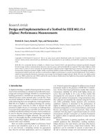
For implantable applications, usually energy is needed to power the
implanted devices. Battery may be a reasonable option as long as it can last for
a long time, avoiding the necessity of frequent medical surgery for battery
replacement. For the case of an implanted device with relatively high power
consumption where an internal battery cannot handle, a wireless
transcutaneous link should be employed. In the 1990s, a single inductive
wireless link composed of two coils is used for both power and data transfer
[14], [15], as shown in Figure 1-2 (a) [14].
However, for applications such as retinal prosthesis and neural recording
during recent years, the data rate increases dramatically from kbps range to
mbps range. This presents a great challenge for utilizing just one inductive
link for both power and data transfer. On one hand, large Quality factor (Q
factor) coils are necessary for better power transfer efficiency, which will be
explained in Chapter 2. On the other hand, larger bandwidth is necessary for
3
larger data handling capacity, which means smaller Q for the coils. Due to this
reason, separate links with respective power and data transmission purpose are
developed, as shown in Figure 1-2 (b) [16].
(a)
(b)
Figure 1-2 (a) Single inductive link used in the power and data transfer system [14] (b)
The block diagram of a neuroprosthetic system with multiple links [16].
Normally, the power link is composed of two inductive coils, either in
circular or rectangular forms [17]-[21], such as the pair of L1 and L2 shown in
Figure 1-2 (b). The power carried by electromagnetic wave is transferred from
outside the body into the implanted device in the human tissue. This type of
power transfer is similar as that of the traditional transformers in electric
power delivery systems, which is based on inductive coupling in the near field,
and the magnetic flux leads to the mutual inductance between two inductors
and therefore ensures the successful transfer of energy. For increasing the self
and mutual inductance and therefore the Q factors, often multi-turn loop coils
with small resistance values are adopted.
4
For most applications, there are two data links, the downlink and the
uplink [22]. The downlink usually transmits control and command signals, and
the data is transferred from outside to inside. Downlink can also be termed as
the forward data telemetry, which is the coil pair of L3 and L4 shown in
Figure 1-2 (b). The uplink transfers the physiological data collected by
implanted bio-sensors and related Integrated Circuit (IC) chips to outside the
human body for processing and analysis, which is the back telemetry A1 and
A2 shown in Figure 1-2 (b). When the data rate requirement is not demanding,
the data link can also be incorporated into the power link as shown in Figure
1-3.
Figure 1-3 The block diagram of an implantable prosthetic system [23].
For the realization of the data link, usually either near-field inductive coils
[22], [23] or far-field antennas [24] are adopted depending on specific
applications. Near-field coils are coupled to each other through inductive
coupling, which is quite effective when operated in the near field, and the
usual operating distance is around 10 mm. However, when the distance is
increased, the efficiency drops significantly. Therefore for long distance
5
operation, coupling antenna pairs resonating at the same frequency are
adopted [24].
1.2 Frequency Bands, Tissue Properties and Safety
Issues
1.2.1 FrequencyBandsforBiomedicalTelemetry
For the operation of wireless links, normally High Frequency (HF) at 3
MHz to 30 MHz is adopted for power transfer [17]-[21], while Very High
Frequency (VHF) at 30 MHz to 300 MHz and Ultra High Frequency (UHF) at
300 MHz to 3 GHz are adopted for data transfer [16], [24], [24]. However,
most of the times, the selection of frequency bands are based on specific
applications rather than being in the strictly predefined range. For instance, in
the case of Figure 1-2 (b) [16], three different frequency bands are selected. A
low-frequency (f
P
< 1 MHz) carrier is selected for power transfer from the
external side to the inside. A medium-frequency (f
FD
= 1 ~ 100 MHz) carrier is
selected for the forward data telemetry. And a high-frequency (f
BT
> 400 MHz)
carrier is selected for the back telemetry.
Table 1-1 Common frequency bands for data communication for biomedical
application
Frequency range Name of band
402 ~ 405 MHz Medical Implant Communication Services (MICS)
1395 ~ 1400 MHz Wireless Medical Telemetry Services (WMTS)
2.4 ~ 2.5 GHz Industrial Scientific Medical (ISM)
3.5 ~ 4.5 GHz Ultra-wideband (UWB)
In general words, for wireless power transfer, the frequency is often
located at around several megahertz or dozens of megahertz range. For data
communication in the far-field, there are several frequently used bands, such
as 402 MHz ~ 405 MHz Medical Implant Communication Services (MICS)
band [26]-[35], 1395 ~ 1400 MHz Wireless Medical Telemetry Services
(WMTS) band [36], 2.4 ~ 2.5 GHz Industrial Scientific Medical (ISM) band
[37]-[39], and 3.5 ~ 4.5 GHz Ultra-wideband (UWB) [40]. We summarize the
6
frequency bands for data communication for biomedical applications in Table
1-1. For ISM band, there are also other band ranges as listed in Table 1-2.
However, 2.45 GHz is most commonly used for data communication for
biomedical implants [9], [37]-[39].
MICS band is allocated to biotelemetry applications according to
Recommendation ITU-R SA.1346, and later superseded by RS. 1346 [41].
However, the band 401-406 MHz is previously allocated to the Meteorological
Aids Service, in order to reduce the harmful interference that might occur to
the operation of Meteorological Aids, a maximum limit of -16 dBm on the
Effective Isotropically Radiated Power (EIRP) of MICS is specified.
Table 1-2 Frequency bands for ISM band
Frequency
range
(MHz)
Centre
frequency
(MHz)
Frequency
range
(GHz)
Centre
frequency
(GHz)
6.765 ~ 6.795 6.78 2.4 ~ 2.5 2.45
13.553 ~ 13.567 13.56 5.725 ~ 5.875 5.8
26.957 ~ 27.283 27.12 24 ~ 24.25 24.125
40.66 ~ 40.70 40.68 61 ~ 61.5 61.25
433.05 ~ 434.79 433.92 122 ~ 123 122.5
902 ~ 928 915 244 ~ 246 245
For ISM band, there are a few frequency ranges, which are summarized in
Table 1-2 [42]. For some of the lower bands in ISM, it is also used for wireless
power transfer, such as 6.78 MHz [21] or 13.56 MHz [18]. 13.56 MHz is also
a Radio-frequency Identification (RFID) band. The higher bands at 433.92
MHz, 915 MHz, 2.45 GHz and 5.8 GHz for data communication are
thoroughly compared in previous work [43]. For all ISM bands, 2.45GHz is
most commonly adopted for data transmission for biomedical applications.
1.2.2 TissuePropertiesandHumanModels
The dielectric properties at different frequencies for different body tissues
have been investigated [44]. Here in Figure 1-4 we show a graph of the
relative permittivity and conductivity of the most commonly used human
tissues: skin, fat and muscle. The figure is plotted with respect to a frequency
span from 0.1 GHz to 10 GHz.
7
0246810
0
2
4
6
8
10
Conductivity
Relative permittivity
Frequency (GHz)
Conductivity (S/m)
0
80
160
240
320
400
Relative permittivity
(a)
0246810
0.0
0.2
0.4
0.6
0.8
Conductivity
Relative permittivity
Frequency (GHz)
Conductivity (S/m)
0
4
8
12
16
Relative Permittivity
(b)
8
0246810
0
3
6
9
12
15
Conductivity
Relative permittivity
Frequency (GHz)
Conductivity (S/m)
0
40
80
120
160
200
Relative Permittivity
(c)
Figure 1-4 Relative permittivity and conductivity of (a) skin-dry (b) fat (c) muscle
[44].
From the figure, we can see that three tissue materials are all quite lossy,
mainly contributed by conductive loss, especially at higher frequency range.
Also, the permittivity is quite large compared to most substrate materials. It
helps in reducing the size of an implantable antenna but also reducing its gain.
Additionally, we can see that the dielectric properties of skin are closer to
muscle, while fat has a much lower relative permittivity.
Tissue model composed of these three layers is often used to evaluate the
performance of an implantable antenna. Also one layer model of skin or
muscle is also frequently adopted. From our experience, the size of tissue
model does not have a big influence on the reflection coefficient of
implantable antennas. However, it will influence their gain and radiation
pattern.
Additionally, human models such as three-dimensional FDTD head model
and shoulder model are used in previous work [26]. Because the actual human
model is composed of many delicate tissue voxels, the simulation of which
9
would be quite time-consuming even for workstations. Therefore for the
saving of simulation time, often part of the human body rather than the whole
human model is imported in the simulation software. And we list various
human models from Computer Simulation Technology (CST) Microwave
Studio in Table 1-3 as an example. And the figures for these human models
are shown in Figure 1-5 [45]. We can see that the human models are quite
complete, including baby, child, male adult, female adult and pregnant woman.
Table 1-3 CST human models
Model Age/Sex Size/cm Mass/kg Resolution / mm
Baby 8-week female 57 4.2 0.85 × 0.85 × 4.0
Child 7y female 115 21.7 1.54 × 1.54 × 8.0
Donna 40y female 176 79 1.875 × 1.875 × 10
Emma 26y female 170 81 0.98 × 0.98 × 10
Gustav 38y male 176 69 2.08 × 2.08 × 8.0
Laura 43y female 163 51 1.875 × 1.875 × 5.0
Katja 43y pregnant, 24w 163 62 1.775 × 1.775 × 4.84
Figure 1-5 Various human models which can be used in CST simulation.
1.2.3 SafetyIssues
For safety concerns, we should evaluate Specific Absorption Rate (SAR).
The SAR is a measure of power absorbed by the human tissue exposed to
electromagnetic radiation, which is also used to evaluate the heating issues
brought by mobile phones previously. The definition of SAR can be given by