Study of speed and force in biomanipulation
Bạn đang xem bản rút gọn của tài liệu. Xem và tải ngay bản đầy đủ của tài liệu tại đây (7.72 MB, 156 trang )
STUDY OF SPEED AND FORCE IN
BIOMANIPULATION
ZHOU SHENGFENG
A THESIS SUBMITTED
FOR THE DEGREE OF DOCTOR OF
PHILOSOPHY
DEPARTMENT OF MECHANICAL
ENGINEERING
NATIONAL UNIVERSITY OF SINGAPORE
2013
DECLARATION
I hereby declare that this thesis is my original work and it has
been written by me in its entirety.
I have duly acknowledged all the sources of information which
have been used in this thesis.
This thesis has also not been submitted for any degree in any
university previously.
ZHOU Shengfeng
10 August 2013
i
Acknowledgments
I would like to express my heartfelt gratitude to Assoc. Prof. Peter, C.Y. Chen
and Assoc. Prof. Chong-Jin Ong, from Department of Mechanical Engineering,
National University of Singapore, for their invaluable guidance, enthusiasm and
patience throughout my PhD study. This thesis would not be possible without
their knowledge and support.
I would like to express my appreciation to Dr. Nam Joo Hoo for generously
sharing his experience and knowledge. I have learned a lot from him pertaining
the microinjection experiments. Special thanks also go to Dr. Masood De-
hghan, for his insightful discussions and suggestions regarding the switching
systems.
I wish to thank all my fellow colleagues, especially group members, Dr. Guofeng
Guan, Mr. Sahan Christie Bandara Herath, Ms. Yue Du, Ms. See Hian Hian
and Dr. Jie Wan for their friendship and all the enjoyable moments together.
I would also like to thank all the staffs from Control and Mechatronics lab for
their kindness and assistance. In particular, Mrs. Ooi-Toh Chew Hoey and
Mdm. Hamidah Bte Jasman provide me plenty of support and help.
I gratefully acknowledge National University of Singapore for providing me the
opportunity to study in Singapore and the research scholarship to fulfill the PhD
study.
Finally, my deepest gratitude goes to my wife and my parents, for their un-
derstanding, emotional support and endless love, through the duration of my
studies. I would also like to thank my beloved niece for all the stories she told
and all the songs she sang to me. I wish her a wonderful life filled with love and
happiness.
ii
Contents
Summary vii
List of Tables ix
List of Figures x
List of Symbols xiii
1 Introduction 1
1.1 Background . . . . . . . . . . . . . . . . . . . . . . . . . . . . 1
1.2 Biomanipulation and Microinjection . . . . . . . . . . . . . . . 3
1.2.1 Speed in Automated Microinjection System . . . . . . 4
1.2.2 Force in Automated Microinjection System . . . . . . . 6
1.3 Needs of Force Control in Cell Mechanobiology . . . . . . . . . 7
1.4 Cellular Tensegrity Structure . . . . . . . . . . . . . . . . . . . 9
1.5 Objectives and Significance . . . . . . . . . . . . . . . . . . . . 12
1.6 Outline . . . . . . . . . . . . . . . . . . . . . . . . . . . . . . 13
2 Literature Review 15
2.1 Automation in Microinjection System . . . . . . . . . . . . . . 15
2.2 Force Sensing and Control in Biomanipulation . . . . . . . . . . 19
2.2.1 Force Sensing Techniques in Biomanipulation . . . . . . 20
2.2.2 Force Control in Biomanipulation . . . . . . . . . . . . 24
iii
2.3 Review of Cellular Tensegrity Model . . . . . . . . . . . . . . . 26
2.3.1 Equations of Motion of a Well-Accepted Six-Strut Cel-
lular Tensegrity Model . . . . . . . . . . . . . . . . . . 27
2.3.2 Prestressability and Reference Solution . . . . . . . . . 30
2.3.3 Three-Dimensional Finite-Element Cellular Tensegrity
Models . . . . . . . . . . . . . . . . . . . . . . . . . . 31
2.4 Neural Network Control of Multi-Input Multi-Output Nonlinear
systems . . . . . . . . . . . . . . . . . . . . . . . . . . . . . . 32
2.4.1 Radial Basis Function Neural Network Based Control
of MIMO systems . . . . . . . . . . . . . . . . . . . . 33
2.4.2 Control of Nonlinear Systems with Input Saturations . . 34
3 Speed Optimization in Automated Microinjection of Zebrafish Em-
bryos 35
3.1 Introduction . . . . . . . . . . . . . . . . . . . . . . . . . . . . 35
3.2 Motivation . . . . . . . . . . . . . . . . . . . . . . . . . . . . . 37
3.3 Dynamics Model of Zebrafish Embryo . . . . . . . . . . . . . . 37
3.3.1 Dynamics Model . . . . . . . . . . . . . . . . . . . . . 39
3.3.2 Estimation of Parameter Values . . . . . . . . . . . . . 41
3.4 Speed Optimization . . . . . . . . . . . . . . . . . . . . . . . . 46
3.4.1 Problem Formulation . . . . . . . . . . . . . . . . . . . 47
3.4.2 Numerical Solution Approach . . . . . . . . . . . . . . 48
3.5 Experiments . . . . . . . . . . . . . . . . . . . . . . . . . . . . 52
3.5.1 Indentation at Constant Speed . . . . . . . . . . . . . . 52
3.5.2 Indentation at Optimized Speed . . . . . . . . . . . . . 53
3.6 Conclusions . . . . . . . . . . . . . . . . . . . . . . . . . . . . 56
4 Force Control of a Cellular Tensegrity Structure with Model Uncer-
tainties and Partial State Measurability 57
iv
4.1 Introduction . . . . . . . . . . . . . . . . . . . . . . . . . . . . 57
4.2 Cellular Tensegrity Model and Task Setting . . . . . . . . . . . 59
4.2.1 Equations of Motion Under External force . . . . . . . . 60
4.2.2 Force-bearing Interaction, Parameter Uncertainties, and
State Measurability . . . . . . . . . . . . . . . . . . . . 63
4.2.3 Control Objective . . . . . . . . . . . . . . . . . . . . . 65
4.3 Notations . . . . . . . . . . . . . . . . . . . . . . . . . . . . . 66
4.4 Force Control Development . . . . . . . . . . . . . . . . . . . . 66
4.4.1 Synthesis of Control Law . . . . . . . . . . . . . . . . . 66
4.4.2 Stability Analysis . . . . . . . . . . . . . . . . . . . . . 68
4.5 Numerical Simulation . . . . . . . . . . . . . . . . . . . . . . . 72
4.6 Conclusions . . . . . . . . . . . . . . . . . . . . . . . . . . . . 75
5 Force Control of a Cellular Tensegrity Model with Time-Varying
Mechanical Properties 76
5.1 Introduction . . . . . . . . . . . . . . . . . . . . . . . . . . . . 76
5.2 Cellular Tensegrity Model and Task Setting . . . . . . . . . . . 77
5.2.1 Cellular Tensegrity Model with Unknown Time-Varying
Stiffness and Damping Coefficient . . . . . . . . . . . . 78
5.2.2 Force-bearing Interaction and System Uncertainties . . . 80
5.2.3 Control Objective . . . . . . . . . . . . . . . . . . . . . 82
5.3 Control Development . . . . . . . . . . . . . . . . . . . . . . . 83
5.3.1 Synthesis of Control Law . . . . . . . . . . . . . . . . . 83
5.3.2 Stability analysis . . . . . . . . . . . . . . . . . . . . . 85
5.4 Numerical Simulation . . . . . . . . . . . . . . . . . . . . . . . 88
5.5 Conclusions . . . . . . . . . . . . . . . . . . . . . . . . . . . . 90
6 Force Tracking Control in Biomanipulation Using Neural Networks 93
6.1 Introduction . . . . . . . . . . . . . . . . . . . . . . . . . . . . 93
v
6.2 Dynamic Model of a Manipulator in Contact with a Cellular
Tensegrity Model . . . . . . . . . . . . . . . . . . . . . . . . . 94
6.2.1 Contact Force Model . . . . . . . . . . . . . . . . . . . 94
6.2.2 Dynamic Model of Manipulator . . . . . . . . . . . . . 95
6.2.3 Control Objective . . . . . . . . . . . . . . . . . . . . . 96
6.3 Notations . . . . . . . . . . . . . . . . . . . . . . . . . . . . . 97
6.4 Control Development . . . . . . . . . . . . . . . . . . . . . . . 97
6.4.1 NN Function Estimation . . . . . . . . . . . . . . . . . 98
6.4.2 Synthesis of Control Law . . . . . . . . . . . . . . . . 100
6.4.3 Stability Analysis . . . . . . . . . . . . . . . . . . . . . 104
6.5 Numerical Simulation . . . . . . . . . . . . . . . . . . . . . . . 113
6.6 Conclusions . . . . . . . . . . . . . . . . . . . . . . . . . . . . 115
7 Conclusions 118
7.1 Summary . . . . . . . . . . . . . . . . . . . . . . . . . . . . . 118
7.2 Contribution . . . . . . . . . . . . . . . . . . . . . . . . . . . . 119
7.3 Future Work . . . . . . . . . . . . . . . . . . . . . . . . . . . . 121
Appendix A 134
Appendix B 136
Appendix C 137
Appendix D 139
vi
Summary
Enhancing the capability of biomanipulation systems has become a pressing
need for advancing the fields of biology and biomedicine. This is particu-
larly motivated by the recent rapid development in the area of mechanobiology,
which studies the comprehensive effect of mechanical stimuli on cellular behav-
ior. One important aspect of biomanipulation is the ability to apply mechanical
forces accurately on biological organisms. Substantial efforts from a wide range
of disciplines have been devoted to developing versatile automated biomanipu-
lation systems. These research efforts have led to various applications of such
systems, yet the issue of how to improve the dexterity of fully automated bioma-
nipulation systems equipped with sophisticated force control capability (in order
to fully realize the potential of such systems) remains a challenging problem in
engineering research. It is in the context of this problem that this thesis explores
the specific issues of speed optimization and force control in biomanipulation
systems.
The first part of this thesis addresses the design of speed trajectories in a mi-
croinjection process, which is a common biomanipulation task, in order to min-
imize adverse physical effects on the biological organism induced by the in-
jection force. An optimization problem in the design of a speed trajectory for
the motion of the micropipette during automated microinjection of zebrafish
embryos is formulated. The objective of this optimization problem is to min-
imize the deformation sustained by the zebrafish embryo. A solution to this
optimization problem is proposed by first constructing a viscoelastic model of
the zebrafish embryo, and then synthesizing an optimal speed trajectory based
on a class of polynomials. Furthermore, results from numerical simulation and
experiments that demonstrate the effectiveness of the proposed solution are pre-
sented. The statistically meaningful experimental data (generated using a large
vii
sample of zebrafish embryos) provide direct evidence on the advantage of such
speed optimization in microinjection.
The second part of this study is devoted to force control of biomanipulation sys-
tems. Mechanical force is known to influence the behavior of biological cells.
To study how external mechanical forces may affect cellular response and cel-
lular function necessitates the development of sophisticated force-control tech-
niques for accurate application of dynamical forces on biological organisms. A
six-strut cellular tensegrity model constructed based on the structural approach
is used for the development of advanced force control techniques, since it pro-
vides a more comprehensive description of the nonlinearity and dynamic cou-
pling of internal structural elements. The force control task is specified in the
context of the six-strut cellular tensegrity model being assigned different prop-
erties. To this end, a homogenous tensegrity model with constant mechanical
properties is first introduced and a robust force control algorithm is proposed to
deal with model uncertainties and partial measurability. A heterogenous tenseg-
rity model with time-varying mechanical properties is subsequently developed
and a robust adaptive control algorithm is proposed to handle the time-varying
feature. Lastly, based on the tensegrity model, a novel neural-network-based
force tracking control for biomanipulation is proposed. The proposed force
controller is readily applicable for the control problem concerning manipulator
interacting with soft compliant materials. Numerical simulations are conducted
to demonstrate the effectiveness of the proposed force control techniques. The
work reported in this thesis represents an initial step in analytical investigation
of localized force-bearing interactions between a cellular tensegrity model and
an external mechanical manipulator.
viii
List of Tables
1.1 Mechanobiological response of Human tendon fibroblasts. Adapted
from [1]. . . . . . . . . . . . . . . . . . . . . . . . . . . . . . . 8
3.1 Parameter values of five indentation trials . . . . . . . . . . . . 45
3.2 Parameters of the hardware . . . . . . . . . . . . . . . . . . . . 49
3.3 Coefficients of optimal speed trajectories. . . . . . . . . . . . . 49
4.1 Values of parameters used in simulation. . . . . . . . . . . . . . 73
ix
List of Figures
1.1 Tensegrity model of the cell. Adapted from [2]. . . . . . . . . . 10
2.1 MANiPEN micromanipulator. Adapted from [3]. . . . . . . . . 17
2.2 (a) Autonomous embryo injection system. (b) Teleoperated em-
bryo injection. Adapted from [4]. . . . . . . . . . . . . . . . . . 17
2.3 (a) Close view of injection area. (b) Centerlines of the ze-
brafish embryos and micropipette. Adapted from [5]. . . . . . . 18
2.4 Vacuum-based zebrafish embryo holding device: (a) Device pic-
ture; (b) Device schematic with embryos immobilized for injec-
tion. Adapted from [6]. . . . . . . . . . . . . . . . . . . . . . . 19
2.5 (a) CAD prototype of mold for cell-holding device. (b) Labo-
ratory test bed suspended cell-injection system. Adapted from
[7]. . . . . . . . . . . . . . . . . . . . . . . . . . . . . . . . . . 20
2.6 Solid model of the multiaxis cellular force sensor. Adapted from
[8]. . . . . . . . . . . . . . . . . . . . . . . . . . . . . . . . . . 21
2.7 PVDF force sensor used for zebrafish embryo injection. Adapted
from [9]. . . . . . . . . . . . . . . . . . . . . . . . . . . . . . . 22
2.8 (a) Force-sensing structure of the PVDF force sensor. (b) PVDF
film with beam structure. Adapted from [10]. . . . . . . . . . . 22
2.9 Side view of the modified piezoresistive micro-force sensor with
the micropipette. Adapted from [5]. . . . . . . . . . . . . . . . 23
x
2.10 (a) Force balance on the cell under indentation. (b) Post deflec-
tion model. Adapted from [11]. . . . . . . . . . . . . . . . . . . 24
2.11 (a) A six-strut cellular tensegrity structure. (b) Orthonormal
base vectors (
⃗
b
1
,
⃗
b
2
,
⃗
b
3
). (c) Configuration of A
3
C
3
. (d) Con-
figuration of B
1
D
1
. . . . . . . . . . . . . . . . . . . . . . . . . 28
3.1 The development cycle of zebrafish embryo . . . . . . . . . . . 36
3.2 Structure of a zebrafish embryo . . . . . . . . . . . . . . . . . . 36
3.3 (a) Indentation of the zebrafish embryo membrane by a mi-
cropipette. (b) The distribution of stress and stain in the de-
formed membrane, where the symbols ξ and σ denote stress
and strain, respectively (max stand for maximum and min stand
for minimum). F denotes the contact force between the mi-
cropipette and the membrane of the embryo. . . . . . . . . . . . 38
3.4 Maxwell-Weichert model having two Maxwell elements. . . . . 40
3.5 A plastic cuboid, with its bottom glued to a transparent plas-
tic sheet, contains the zebrafish embryo. It has a vertical wall
to keep the embryo stationary when being indented by the mi-
cropipette (which is actuated by a 3-axis positioning stage). The
holder that supports this sheet is mounted on a 6-dof motion
stage that can be manoeuvred to algin the wall of the cuboid to
be perpendicular to the direction of motion of the micropipette.
A force sensor, incorporated in the micropipette, measures the
indentation force, while a digital camera, positioned directly
above the cuboid, captures the view of the microscope. . . . . . 41
3.6 Schematic illustration of (a) the overall micromanipulation sys-
tem; (b) the small pool area. . . . . . . . . . . . . . . . . . . . 42
3.7 Close-up view of the contact between the micropipette and the
embryo. . . . . . . . . . . . . . . . . . . . . . . . . . . . . . . 43
3.8 Curve fitting of data from experiment using a Maxwell-Wiechert
model with two Maxwell elements. . . . . . . . . . . . . . . . . 43
xi
3.9 Force responses of zebrafish embryos predicted by the analyt-
ical model and measured from experiments. The smooth solid
curves are generated from the model using the paramater val-
ues listed in Table 3.1. The jagged curves are obtained from
experimental data. . . . . . . . . . . . . . . . . . . . . . . . . . 45
3.10 Curve-fitting of force trajectory using a Maxwell-Wiechert model
with only one Maxwell element. . . . . . . . . . . . . . . . . . 46
3.11 (a) Minimum deformation at different Time τ
∗
. (b) Trajectory
of v(t) for τ
∗
=0.2s. (c) Deformation and force for τ
∗
=0.2 sec. 50
3.12 Minimum deformation with v(t) of 0
th
, 3
rd
, and 4
th
order poly-
nomials over an interval of τ. . . . . . . . . . . . . . . . . . . 51
3.13 Deformation (with one standard deviation) of zebrafish embryo
under indentation at constant speed. . . . . . . . . . . . . . . . 52
3.14 Comparison between experiment and simulation for constant
speed . . . . . . . . . . . . . . . . . . . . . . . . . . . . . . . 53
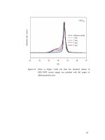
3.15 Optimized speed trajectory and its approximate implementation. 54
3.16 Deformation of zebrafish embryos obtained from experiments.
The top curve is the same as that shown earlier in Figure 3.14 for
the period of [0, 4] seconds. In the bottom curve, each triangle
represents the average value from 10 trials, with the number in
brackets being the standard deviation. . . . . . . . . . . . . . . 55
4.1 A spherical tensegrity structure with intermediate filaments used
to generate the computational tensegrity model. . . . . . . . . . 59
4.2 Characterization of B
1
D
1
with external force applied on point
G, where 0 ≤ r ≤ L, with L being the length of B
1
D
1
. α
12
,
δ
12
, X
1
, Y
1
, Z
1
are of the same definitions as in Section 2.3.1. . . 61
4.3 Schematics of proposed robust controller. . . . . . . . . . . . . 72
4.4 Trajectories of the two types of desired force used in the simu-
lations. . . . . . . . . . . . . . . . . . . . . . . . . . . . . . . . 73
4.5 Force tracking error with respect to a step desired force. . . . . . 74
xii
4.6 Force tracking error with respect to a sinusoidal desired force. . 74
5.1 Trajectories of the two types of desired force used in the simu-
lations. . . . . . . . . . . . . . . . . . . . . . . . . . . . . . . . 88
5.2 Force tracking error with respect to a step desired force. . . . . . 90
5.3 Force tracking error with respect to a sinusoidal desired force. . 91
6.1 Magnitude and rate limiter, where w
i
is the bandwidth parameters.100
6.2 Desired force trajectory . . . . . . . . . . . . . . . . . . . . . . 113
6.3 Force tracking error: (a) e
x
. (b) e
y
. (c) e
z
. . . . . . . . . . . . . 114
6.4 (a) Φ(ϱ
∗
1
). (b) Φ(ϱ
∗
2
). (c) Φ(ϱ
∗
3
). . . . . . . . . . . . . . . . . . . 115
6.5 (a)
˙
Φ(ϱ
∗
1
). (b)
˙
Φ(ϱ
∗
2
). (c)
˙
Φ(ϱ
∗
1
). . . . . . . . . . . . . . . . . . . 116
6.6 Norm of ξ . . . . . . . . . . . . . . . . . . . . . . . . . . . . . 117
xiii
List of Symbols
Symbols in Chapter 3
A : Maximum acceleration
b
2,3
: Damping ratio in Maxwell-Weichert Model
c
0, ,n
: The coefficients of the velocity of n
th
-order polynomial
D : Maximum deceleration
F
∗
: The force at τ
∗
(maximum force)
f(t): Identation force acting on the membrane
k
1,2,3
: Stiffness in Maxwell-Weichert Model
t : Time
t
′
: The time constant when the micropipette stops indenting motion
x(t): Displacement of micropipette
V : Maximum velocity
v(t): Velocity of micropipette
ϵ : An infinitesimal positive value
τ
∗
: The instant when the embryo is just to be pierced
Ω
v
: The set of all speed trajectories implementable on a given system
xiv
Symbols in Chapter 4, 5 and 6
A(q): Equilibrium matrix
A
f
(q
f
): Modified equilibrium matrix
a
i
The center of the receptive field
b
i
The width of the Gaussian function
c : The constant damping coefficient
c(t): The time-varying damping coefficient
C(q): Damping matrix
C
f
(q
f
): Modified damping matrix
C
r
: The Centripetal-Coiolis effects matrix
f : The contact force
f
d
The desired force
˙
f
d
The time deravative of the desired force
f
ti
: The force sustained by the ith tendon
g
r
: The conservative forces
H(q): Disturbance matrix
H
f
(q
f
): Modified disturbance matrix
H
r
: The inertial matrix of the manipulator
k : The constant stiffness
k
i
(t): The time-varying stiffness of ith tendon
l
i
: The length of the tendon
l
i0
: The length of the initial length of the tendon
˙
l
i
: The time derivative of l
i
xv
q
f
: The modified vector of generalized coordinates
q
1
: The Cartesian coorodinates of the contact point G
q
2
: The elments of the modified generalized coordiates exluding those in q
1
S : The basis function in raddial basis function neural newok
T (q): Tensions in the working tendons
T
f
(q
f
): Modified tensions in the working tendons
W
∗
The ideal weights of raddial basis function neural newok
u : The control input of the manipulator
ϵ : The corresponind error of neural network estimation
λ
max
(A): The largest eigenvalue of a square matrix A
λ
min
(A): The smallest eigenvalue of a square matrix A
∥A∥ : The Frobenius norm of any matrix A
∥A∥
I
: The induced norm of any matrix A
∥B∥ : The standard Euclidean norm of any vector B
xvi
Chapter 1
Introduction
1.1 Background
Biomanipulation refers to the manipulation (e.g.,positioning and grasping) of
biological materials/structures (e.g. cells and embryos). It is a common process
in biology, biomedicine related practise and areas involving handling of biolog-
ical materials. Over the last two decades, it has attracted considerable research
interests from a wide range of disciplines and various engineering approaches
have been developed. The key approaches developed involve mechanical tech-
niques, magnetic and electrical field based methodologies, optics based means
and microelectromechanical systems (MEMS) based approaches. Despite these
research efforts and advancements, developing novel means to further expand
the biomanipulation capability is still an active research area. The direction
of recent research focuses on developing sophisticated engineering platforms
featuring the integration of force sensing techniques, which enables quantita-
tive investigation of the force the biological material/structure sustains during
biomanipulation.
1
Cell manipulation is one of the most common biomanipulation techniques. It
is the crucial step in performing some molecular biology tasks such as DNA
microinjection and intracytoplasmic sperm injection (ICSI). The conventional
method of single cell manipulation is manual and its success mainly depends
on the experience of the operator. Therefore, operator-related factors, such as
contamination and poor reproducibility, are inextricable and result in a rela-
tively low success rate. To address these shortcomings, considerable research
efforts have been made to automate cell manipulation processes. Most of these
efforts concentrate on developing automation systems for the microinjection of
zebrafish embryo, due to its wide application in biology study.
These substantial progresses in automating the microinjection process notwith-
standing, some factors which play an important role in the injection process have
not been fully explored, especially in the aspect of improving the capability of
microinjection systems. The speed design in microinjection is such a factor
which has not been explicitly studied. Besides microinjection speed, the role of
force feedback and force control in microinjection is well recognized in the con-
text of performance improvement. Moreover, the advancement in mechanobi-
ology, the study of how mechanical forces affect cells, further emphasizes the
profound role of force and force control in biomanipulation. As a result, novel
and efficient tools and means of force sensing at cellular and subcellular levels
have been developed for cell mechanobiology study. However, most of research
efforts concentrate on developing hardware platforms while less work has been
done on exploring sophisticated control algorithms to achieve accurate control
of dynamic forces applied on living cells.
The force control problem necessitates the modelling of cell behavior under ex-
ternal force. Approaches based on continuum and structural mechanics have
been shown to be useful in constructing mechanical models of living cells. Cel-
lular tensegrity model from the structural approach offers a potentially more
2
effective alternative to those models derived from continuum approach. It is
capable of simulating many aspects of cell mechanical behavior and providing
biologically plausible explanations for such behaviors. However, its potential
for force control application in biomanipulation has not been explored.
The remainder of this chapter provides a brief overview of biomanipulation and
microinjection whilst a more detailed review of the automated biomanipulation
systems is presented in Chapter 2. An introduction of mechanobiology is then
presented with the engineering perspective highlighted. Subsequently, cellular
tensegrity model is introduced while a more detailed review will be discussed in
Chapter 2. Finally, the objectives and potential contributions of this thesis are
presented.
1.2 Biomanipulation and Microinjection
In the field of biology and biomedicine, transportation, orientation and injection
of cell and similar micro biological structures are often required. Such manipu-
lations of biological materials/structures are referred to as biomanipulation[12].
The key component of a biomanipulation setup is the micromanipulator which
scales down the magnitude of motions from the operator to the end-effector. The
movement of the end-effector is usually observed through high-magnification
microscopes. The modern biomanipulation systems are equipped with high-
resolution actuators (e.g. high-resolution motors and piezoelectric actuators)
which are capable of precise control. However, the capabilities of these bioma-
nipulation devices are not fully realized when the tasks are performed manually
since competence of the operator is required and highly dependent. Moreover,
even for an operator with experience, it is not possible to guarantee the success
of the manipulation due to human-related factors, such as fatigue and contami-
nation.
3
To address the limitations of manual operation in biomanipulation, a number of
researchers with multidisciplinary backgrounds are motivated to develop auto-
mated biomanipulation systems. Most of these research works focus on au-
tomating the microinjection system for zebrafish embryos[5, 13]. The mo-
tivation for zebrafish embryo microinjection arises from many factors. First
of all, microinjection is a prevalent process in many applications involving
in vitro fertilization, intracytoplasmic sperm injection, gene therapy and drug
development[14]. Since zebrafish embryos is widely used as experimental sub-
jects in biology on account of a number of its characteristics (e.g., transparent,
genetically manipulatable, fast development), the injection of zebrafish embryo
is one of the most common encountered biomanipulation tasks[15]. Secondly,
the developed automated microinjection system for zebrafish embryo is repre-
sentative of microinjection systems since it consists of all the crucial compo-
nents, such as micromanipulator, microinjector and positioning stage. More-
over, the control techniques (e.g., vision control and force control) developed
in microinjection system are readily applicable for other biomanipulation sys-
tems.
1.2.1 Speed in Automated Microinjection System
Microinjection of zebrafish embryo is a common practice in studying the early
developmental processes of biological organisms. Conventional manual mi-
croinjection usually involves an operator moving the micropipette towards the
embryo until its tip slightly touches the chorion, then driving the micropipette
to pierce the chorion and maneuvering the tip of the micropipette to a desired
location inside the embryo to delivery the DNA material. Such manual opera-
tion relies on visual information from optical devices to guide the operator, and
is prone to errors (due to various human factors such as fatigue). Approaches
4
reported in the literature for improving the process mainly concentrate on pro-
viding haptic feedback to the operator (e.g., [16, 17]) and automating the overall
process (e.g., [18, 19]). Considering the requirements of high reproducibility
and capability of mass processing (batch biomanipulation), automation of the
microinjection process is apparently the more promising approach.
Great advancements have been made in automation of microinjection process.
A large portion of them aim at developing devices/systems and control tech-
niques to facilitate the automated process. Some microinjection system towards
automatic batch microinjection are developed[6]. These systems consist of a in-
verted microscope, a micromanipulator, a micropipette and an injector. They are
able to precisely deliver genetic material to the desired region or specific target
within the zebrafish embryo. However, the microinjection speed and its effects
on the embryo is not explicitly studied within the context of further improving
the performance of the microinjection system.
The performance of a microinjection process can be evaluated in various con-
text. From a pure biological perspective, the survival rate of the injected em-
bryos is one key performance indicator. From a bio-mechanical perspective, the
deformation sustained by the embryo is an important factor to consider, since a
large deformation can damage the embryo to the extent of adversely affecting
its survivability. Since speed of the micropipette is directly related to the defor-
mation of embryo, the study of injection speed may benefit the microinjection
process in terms of minimizing the deformation during the indentation.
The investigation of the microinjection speed is motivated by the fact that em-
bryos exhibit viscoelastic behavior that can be described by analytical models.
In particular, when the micropipette indents an embryo at different speeds, the
peak contact force and the embryo deformation vary accordingly. Leveraging on
viscoelastic models which describe a complex relationship among the applied
5
force, the speed of indentation, and the deformation of the embryo, it is worthy
to study how the microinjection speed affects the reaction force and deformation
of zebrafish embryo under indentation during the microinjection process.
1.2.2 Force in Automated Microinjection System
Vision sensing has been the primary modality for early developed automated
microinjection systems since it enables precise delivery of genetic material to
desired region within the embryo. However, a successful delivery of genetic
material does not guarantee a successful microinjection task considering that
the damage to embryo induced by injection process may cause the demise of
the embryo and thus the failure of the injection task. It has been realized that
the force during the penetration procedure is an important factor defining the
mechanical injury resulted by injection process. For instance, the embryo after
injection has a lower survival rate when the applied force during penetration
process exceeds some threshold.
Importance of the role that force plays in microinjection has prompted the in-
tegration of force sensing and control into the microinjection system for per-
formance improvement. The objective of these works is to regulate the force
during indentation to follow a reasonable desired force trajectory, such as the
force trajectory extracted from a proficient technician. The main contribution
of these works is the development of various types of force sensing techniques
and their integration with the microinjection system. It is noted that the control
techniques developed are direct application of conventional robot force con-
trol strategies (e.g., PID control and impedance force control). Moreover, these
developed force control techniques are based on relatively simple mechanical
models constructed from the continuum approach. Although adequate for sim-
ple mechanical environment usually encountered in conventional robotic manip-
6
ulation tasks, these models fall short of capturing the rich dynamics exhibited
by living biological cells. For instance, there are only a few works considering
the viscoelasticity of the biological materials for force control in microinjec-
tion/biomanipulation.
From above discussions, it can be concluded that the existing force control ap-
proaches developed for microinjection/biomanipulaiton is preliminary. Suitable
modeling of mechanical response of biological materials/structures is vital to
realize precise control of applied force on them. Among various mechanical
models of living cells, tensegrity model has gained its acceptance in the sci-
entific community since it has been proved to be capable of simulating many
aspects of cell mechanical behavior and providing plausible biological expla-
nations for such behavior. A detailed discussion of cellular tensegrity model is
presented in section 1.3.
1.3 Needs of Force Control in Cell Mechanobiol-
ogy
Living cells are constantly subjected to diverse mechanical stimuli from a wide
array of sources, including forces generated internally and applied externally.
The external mechanical forces exerted on the living cells are known to affect
cellular behaviors and functions. Evidences of that mechanical force contributes
to the regulation of cell activities, such as gene induction, protein synthesis and
a variety of other cellular activities which are essential to cells to maintain ap-
propriate biological functions, are well recognized[1]. An representative exam-
ple is that abnormal mechanical loading will cause cells dysfunction[20]. The
study of how mechanical forces affect cell is referred to as cell mechanobiol-
ogy. Enormous research devoted to cell mechanobiology notwithstanding, the
7
Table 1.1: Mechanobiological response of Human tendon fibroblasts. Adapted from
[1].
Response Type of load/force/duration Significance
Increase in cell Uniaxial stretch, 0.5Hz, 4h Stretch magnitude
proliferation, collagen with 4 and 8% -dependent
I gene expression, and response
Collagen I protein
Increase in cell Cyclic biaxial stretch, 5%, Stretch time-depend-
proliferation 1 Hz, 6, 12, and 24 h ent response
Decrease in cell Cyclic biaxial stretch, 5%,
proliferation 1 Hz, 48h
mechanism of how cells respond to the external mechanical forces is largely
insufficiently studied. Table 1.1 lists some of the mechanobiological response
of a type of cell, human tendon fibroblast, to different mechanical loads (e.g.,
type of force and duration of force). From Table 1.1, it is clearly indicated that
different mechanical stimuli result in different cell behavior.
A crucial challenging issue facing cell mechanobiology is the precise control
of the mechanical stimuli applied on living cells. This has raised plenty of
research interests in engineering community. Various engineering approaches
including mechanical, magnetic, optical and microelectromechanical systems
(MEMS) techniques, have been developed for quantitative investigation of me-
chanical loads that the cells are subjected to and the biomechanical responses
(e.g., cellular deformation)[14]. Moreover, novel micro-engineered platforms
integrated with these key methodologies have been developed with the objec-
tive of simulating the vivo-like environment that the living cell experience in
an in vitro settings[21]. These approaches and platforms not only significantly
facilitate the study of cell mechanobiology, but also contribute to the area of
biomanipulation where quantitative information about force applied on living
cells is concerned.
Although substantial progress has been achieved in developing novel and ef-
8