Improving the mechanical and functional performance of extrusion based additive manufactured scaffolds for bone tissue engineering
Bạn đang xem bản rút gọn của tài liệu. Xem và tải ngay bản đầy đủ của tài liệu tại đây (5.62 MB, 195 trang )
IMPROVING THE MECHANICAL AND FUNCTIONAL
PERFORMANCE OF EXTRUSION-BASED ADDITIVE
MANUFACTURED SCAFFOLDS FOR BONE TISSUE
ENGINEERING
MUHAMMAD TARIK ARAFAT
NATIONAL UNIVERSITY OF SINGAPORE
2011
IMPROVING THE MECHANICAL AND FUNCTIONAL
PERFORMANCE OF EXTRUSION-BASED ADDITIVE
MANUFACTURED SCAFFOLDS FOR BONE TISSUE
ENGINEERING
MUHAMMAD TARIK ARAFAT
(B.Sc in Mechanical Engineering, BUET)
A THESIS SUBMITTED
FOR THE DEGREE OF DOCTOR OF PHILOSOPHY
DEPARTMENT OF MECHANICAL ENGINEERING
NATIONAL UNIVERSITY OF SINGAPORE
2011
Acknowledgements
i
Acknowledgements
First and foremost, I would like to thank Associate Professor Ian Gibson. It is my
pleasure to get him as my supervisor. His tender attention, patience, suggestions and
prudence guidance encourage me throughout my candidature.
I would like to express my gratitude to Dr Li Xu (Senior scientist I, IMRE) for
supervising me during the last three years. His valuable guidance, continuous support
and passion towards science encourage me throughout the difficult period of my
research.
I would like to thank National University of Singapore (NUS) for the NUS research
scholarship and state of the art research facilities. I would also like to acknowledge the
financial support for this research from the A*STAR Program under Grant No. R 397
000 038 305.
I am grateful to all those colleagues, seniors and friends who have helped me in my
PhD research when I was in need. My special thanks goes to Chris Lam for his
guidance to develop my laboratory skills, Anand for his true support during the screw
extrusion system development and maintenance, and Andrew for his valuable
suggestions. I would also like to thank Liu Yuan and Dr. Monica for helping me a lot
during the initial phase of my research. I would like to take this opportunity to convey
my appreciation to Tanveer, Enamul, Pervej, Chandra Nath, Ahsan Habib, Afzal,
Aravind, Asma, Anower, Zakaria, Abdul Hannan, Abu Taiyob and many more for
Acknowledgements
ii
being supportive. I would also like to acknowledge the effort of FYP student Daniel and
Luo Hui.
My heartfelt gratitude goes to my father Mr. Md. Shahjahan and Mrs. Monowara
Begum for their blessings and mental support. I would also like to convey my gratitude
to my younger brother Muhammad Tanvir Arafat for his inspiration. Last but not the
least; I would like to convey my gratitude to my beloved wife Farhana Hoque for her
prayer, inspiration and for always being with me.
Table of contents
iii
Table of Contents
Acknowledgements i
Table of contents iii
Summary xi
Abbreviations xiv
List of Figures xvii
List of Tables xxiii
Chapter 1 Introduction 01
1.1 Background 01
1.2 Challenges in additive manufactured bone TE scaffolds 02
1.3 Research hypothesis and objectives 04
1.4 Significance of the research 05
1.5 Structure of thesis 06
Chapter 2 Literature review 08
1.1 Background 08
2.2 Background of scaffold technology 09
2.3 Design of scaffolds 11
2.3.1 Porosity and pore size of scaffolds 11
2.3.2 Architecture of scaffolds 12
2.4 Materials of scaffolds 14
2.4.1 Bioactive ceramic phases 14
2.4.2 Biodegradable polymer matrices 15
Table of contents
iv
2.4.3 Polymeric/ceramic composite scaffolds 18
2.5 Fabrication of scaffolds 19
2.5.1 Conventional fabrication techniques 19
2.5.2 Additive manufacturing techniques 19
2.5.2.1 Stereolithography apparatus (SLA) 20
2.5.2.2 Selective laser sintering (SLS) 22
2.5.2.3 Three-dimensional printing (3DP) 24
2.5.2.4 Extrusion based system 25
2.6 Modification of scaffolds 28
2.6.1 Through combinational approach 28
2.6.2 Through surface modification 30
2.7 Conclusions 32
Chapter 3 Screw extrusion system (SES) and its fabricated scaffolds 34
3.1 Introduction 34
3.2 Main features of in-house SES 35
3.2.1 Extruder screw 35
3.2.2 Extruder body part 36
3.2.3 Extruder nozzle 39
3.3 Evaluation of scaffolds fabricated via in-house SES 40
3.3.1 Scaffold Material 40
3.3.2 Scaffold design 40
3.3.3 Scaffold fabrication 41
3.3.4 Characterization of scaffolds 42
Table of contents
v
3.3.4.1 Porosity measurement 42
3.3.4.2 Morphology 44
3.3.4.3 Mechanical experiments 44
3.3.5 In vitro cell culture study 45
3.3.5.1 Cell seeding on scaffolds 45
3.3.5.2 Morphology of the cell-scaffolds constructs 45
3.3.5.3 AlamarBlue 46
3.3.6 Results and discussions 47
3.3.6.1 Porosity and dispensing speed 47
3.3.6.2 Modulus and dispensing speed 50
3.3.6.3 In vitro cell culture results 52
3.3.7 Conclusions 53
Chapter 4 Improvement of mechanical properties of additive manufactured
PCL/TCP scaffolds 54
4.1 Introduction 54
4.2 Part I – Silanized PCL/TCP(Si): composite synthesis, scaffolds fabrication
and characterization 57
4.2.1 Materials and methods 57
4.2.1.1 Materials 57
4.2.1.2 Synthesis of PCL/TCP(Si) 57
4.2.1.3 Fabrication of the PCL/TCP(Si) scaffolds by SES 57
4.2.1.4 Characterization 58
4.2.1.5 Cell seeding on scaffolds 59
Table of contents
vi
4.2.1.6 Morphology of the cell-scaffold constructs 59
4.2.1.7 PicoGreen® Assay 60
4.2.1.8 Gene Expression (Real-time RT-PCR) 60
4.2.1.9 Western Blot Study (WB) 60
4.2.1.10 Statistical Analysis 61
4.2.2 Results and Discussions 62
4.2.2.1 PCL/TCP(Si) composite preparation and scaffolds
fabrication 62
4.2.2.2 In vitro cells response 67
4.2.3 Conclusions 72
4.3 Part II – POSS modified PCL/TCP(Si): composite synthesis, scaffolds
fabrication and characterization 73
4.3.1 Materials and methods 73
4.3.1.1 Materials 73
4.3.1.2 Synthesis of PCL/TCP(POSS) 73
4.3.1.3 Fabrication of the PCL/TCP(POSS) scaffolds by SES 73
4.3.1.4 Characterization 73
4.3.1.5 Cell seeding on scaffolds 74
4.3.1.6 Morphology of the cell-scaffold constructs 74
4.3.1.7 PicoGreen® Assay 74
4.3.1.8 Alkaline phosphate activity (ALP) 75
4.3.1.9 Statistical Analysis 75
4.3.2 Results and Discussions 75
Table of contents
vii
4.3.2.1 PCL/TCP(POSS) composite preparation and scaffolds
fabrication 75
4.3.2.2 In vitro cells response 80
4.3.3 Conclusions 83
Chapter 5 Development of biomimetic composite coating on PCL/TCP(Si)
scaffolds 85
5.1 Introduction 85
5.2 Materials and methods 87
5.2.1 Materials 87
5.2.2 Fabrication of PCL/TCP(Si) scaffolds by SES 87
5.2.3 Surface coating on PCL/TCP(Si) scaffolds 88
5.2.4 Scaffolds characterizations 89
5.2.5 Compression testing 89
5.2.6 Cell seeding on scaffolds 90
5.2.7 Morphology of cell-scaffolds constructs 90
5.2.8 PicoGreen® assay 90
5.2.9 Reverse transcription polymerase chain reaction (RT-PCR) 90
5.2.10 Western Blotting (WB) 90
5.2.11 Statistical analysis 91
5.3 Results and discussions 91
5.3.1 Scaffolds fabrication 91
5.3.2 Biomimetic CHA-gelatin composite coating 91
5.3.3 Scaffold characterization 93
Table of contents
viii
5.3.4 In vitro cells response 98
5.4 Conclusions 105
Chapter 6 Development of additive manufacturing-freeze drying integrated
scaffolds with POSS modified PCL/TCP scaffolds 107
6.1 Introduction 107
6.2 Materials and methods 109
6.2.1 Materials 109
6.2.2 Fabrication of POSS modified PCL/TCP scaffolds by SES 109
6.2.3 Forming porous gelatin structure within the pores of the
PCL/TCP(POSS) scaffolds and its characterization 110
6.2.4 Cell seeding on scaffolds 110
6.2.5 Morphology of the cell-scaffolds constructs 110
6.2.6 PicoGreen® assay 111
6.2.7 Alkaline phosphate (ALP) activity 111
6.2.8 Statistical analysis 111
6.3 Results and discussions 111
6.3.1 Fabrication of PCL/TCP(POSS) scaffolds by SES 111
6.3.2 Hierarchical PCL/TCP(POSS)-foam scaffolds to improve the
functional performance of additive manufactured scaffolds 112
6.3.3 In vitro cell response 115
6.4 Conclusions 118
Table of contents
ix
Chapter 7 In vivo evaluation of apatite coated additive manufactured scaffolds in a
rat calvarial defect model 119
7.1 Introduction 119
7.2 Materials and methods 121
7.2.1 Materials 121
7.2.2 PCL/TCP(Si) composite preparation and scaffolds fabrication 121
7.2.3 Biomimetic CHA and CHA-gelatin coating on PCL/TCP(Si)
scaffolds 122
7.2.4 In vitro studies 122
7.2.4.1 Cell seeding on scaffolds 122
7.2.4.2 Morphology and viability study of cell-scaffold constructs
a 122
7.2.4.3 ALP 122
7.2.4.4 PicoGreen® Assay 123
7.2.5 In vivo studies 123
7.2.5.1 Animal Surgery 123
7.2.5.2 Experimental design 123
7.2.5.3 Anesthesia and Pre-operative considerations 124
7.2.5.4 Surgical procedure 124
7.2.5.5 MicroCT 125
7.2.5.6 Mechanical testing 125
7.2.6 Statistical analysis 126
7.3 Results and discussions 127
Table of contents
x
7.3.1 PCL/TCP(Si) composite preparation, scaffolds fabrication and
biomimetic coating on scaffolds 127
7.3.2 In vitro studies 127
7.3.3 In vivo studies 130
7.3.3.1 Animal surgery 130
7.3.3.2 Micro-CT 131
7.3.3.3 Mechanical testing 133
7.4 Conclusions 136
Chapter 8 Conclusions and recommendations 137
8.1 Conclusions 137
8.1.1 Improvement of the mechanical properties of the additive
manufactured scaffolds 138
8.1.2 Improvement of the proliferative and osteoconductive properties of
the additive manufactured scaffolds 139
8.1.3 Improvement of the functional performance of the additive
manufactured scaffolds 140
8.1.4 Evaluation of the biomimetic composite coated additive
manufactured scaffolds in vivo 141
8.2 Limitations and recommendations 142
References 144
List of publications 161
Appendix A-1
Summary
xi
Summary
Scaffold-based tissue engineering (TE) aims to aid in the repair and regeneration of
bone defects. Bone defects due to high energy trauma, bone resections, congenital
malfunction and severe non-union fractures require a bone substitute for regeneration.
At present, the demand of most commonly used bone substitute autogenous cancellous
bone grafts far exceeds the supply. Moreover, it is not an ideal solution due temporary
disruption of donor site bone structure and considerable donor site morbidity associated
with the harvest. Hence, the development of new synthetic bone substitutes or scaffolds
that could be used instead of autogenous cancellous bone grafts has become a key
priority in bone TE.
In scaffold-based bone TE the scaffold acts as a platform to carry cells or
therapeutic agents for regenerative therapies. An ideal scaffold is required to mimic the
mechanical and biochemical properties of the native tissue. To effectively achieve these
properties, a scaffold should be mechanically robust with suitable architectural qualities
to favour flow transport of nutrient for cell growth. It should also have osteoconductive
properties to support cells through suitable surface chemistry. In this context high
performance extrusion based additive manufactured scaffolds were developed for bone
tissue engineering by improving their mechanical, biochemical and cell seeding
efficiency.
Mechanical properties of the polymeric/ceramic scaffolds were improved by
enhancing the interfacial interaction between the polymeric and ceramic phase through
the use of coupling agents. Two different coupling agents, namely silane and POSS
Summary
xii
have been used in this research project. The main idea of using a coupling agent was to
improve the interfacial interaction between the ceramic and polymer phase. Both of the
developed silanized poly (ε-caprolactone)/tricalcium phosphate (PCL/TCP) and POSS
modified PCL/TCP scaffolds have significantly improved mechanical properties and
are suitable to use for cancellous bone tissue engineering. No detrimental effect of
silane modification was found on cells. On the other hand POSS modified scaffolds
showed better proliferative capability compared to control PCL/TCP scaffolds, which is
due to the exposed TCP on the POSS modified PCL/TCP scaffolds.
To improve the proliferative and osteoconductive properties of the developed
silanized PCL/TCP scaffolds, a thin layer of carbonated hydroxyapatite (CHA)-gelatin
composite was coated onto the scaffolds by biomimetic co-precipitation process. In
vitro studies showed promising results of the biomimetic composite coated scaffolds on
proliferation and osteogenic differentiation of porcine bone marrow stromal cells. In
vivo study was also conducted to evaluate the performance of biomimetic composite
coated samples.
To improve the functional performance of developed POSS modified PCL/TCP
scaffolds by providing a cell entrapment system, a novel hierarchical scaffold that
combines the advantageous properties of AM scaffold and porous foam scaffold was
developed. In the hierarchical structure PCL/TCP(POSS)-foam scaffolds the macro-
sized PCL/TCP(POSS) filaments provide mechanical support and the porous gelatin
foam structure formed by freeze drying acts as a cell entrapment system. From the
manufacturing point of view, to fabricate hierarchical scaffolds, our developed
approach is considerably simpler than combining electrospinning with AM. In vitro
Summary
xiii
results showed notably higher proliferative capability on PCL/TCP(POSS)-foam
scaffolds compared to PCL/TCP(POSS) scaffolds.
In summary, it has been found that coupling agents improve mechanical properties
of the polymer/ceramic scaffolds significantly. Scaffolds with improved mechanical
properties can be further modified to enhance functional performance of the scaffolds.
This study will make a significant contribution in the field of extrusion based AM
scaffolds by improving mechanical properties of the scaffolds by using coupling agents,
and functional performance of the scaffolds by developing thin biomimetic composite
coating and hierarchical structure for cells entrapment system.
Abbreviations
xiv
Abbreviations
3DP - Three dimensional printing
AM - Additive manufacturing
BMP - Bone morphogenic protein
BMSC - Bone marrow stromal cells
DMEM - Dulbecco’s modified Eagle’s medium
CAD - Computer aided design
CHA - Carbonated hydroxyapatite
CT - Computed tomography
EDC - 1-ethyl-3-(3-dimehylaminopropyl) carbodiimide hydrochloride
FBS - Fetal bovine serum
FD - Filament distance
FDA - Food and Drug Administration
FDA - Fluorescein diacetate
FDM - Fused deposition modeling
FG - Fill gap
Abbreviations
xv
FTIR - Fourier transform infrared spectroscopy
GPTMS - 3-glycidoxypropyl trimethoxysilane
HA - Hydroxyapatite
LG - Layer gap
LTDM - Low temperature deposition modeling
MRI - Magnetic resonance imaging
NHS - N-hydroxysuccinimide
SEM - Scanning electron microscopy
TE - Tissue engineering
PBS - Phosphate buffer saline
PCL - Poly (ε-caprolactone)
PEEK - Polyetheretherketone
PEG - Poly (ethylene glycol)
PGA - Poly(glycolic acid)
PHBV - Poly(hydroxybutyrate-cohydroxyvalerate)
PI - Propidium iodide
PPF - Poly (propylene fumarate)
Abbreviations
xvi
PLA - Poly(lactic acid)
PLGA - L,L-lactide-co-glycolide)
RW - Road width
SBF - Simulated body fluid
SES - Screw extrusion system
SLA - Stereolithography apparatus
SLS - Selective laser sintering
ST - Slice thickness
TCP - Tri calcium phosphate
XPS - X-ray photo electron spectroscopy
List of figures
xvii
List of figures
Figure 2.1 Primary considerations for TE.
10
Figure 2.2
Block diagram of the main areas of the scaffold technology.
10
Figure 2.3
Graded scaffolds (a) with controlled porosity with varying pore
geometry via FDM; (b) proposed hybrid scaffolds by our group,
where zone i: bone phase, PCL/20%TCP with 65-70% porosity;
zone ii: bone plate phase, PCL/20%TCP with 30-40% porosity;
zone iii: calcified cartilage phase, PCL/10%TCP with 70-75%
porosity and zone iv: cartilage phase, PCL with 70-75% porosity.
12
Figure 2.4
Schematic of (a) traditional scaffold fabricated by FDM type
system, (b) structure proposed by us for channeling and (c) SEM
images of the structure for channeling or storage of nutrients.
13
Figure 2.5
3DP scaffolds with layers inclined at an angle of 45º.
14
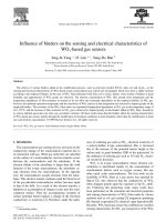
Figure 2.6
Graphical illustrations of (A) the conventional FDM system (B)
compressed air extrusion system (C) screw-extrusion system.
27
Figure 2.7
Elements contributing to scaffold technology.
33
Figure 3.1 In house extruder part 35
Figure 3.2
Extruder screw.
36
Figure 3.3
Parts of extruder frame.
37
Figure 3.4
(a) Extruder centric frame and (b) Front support screws.
37
Figure 3.5
Vertical barrel replacement.
38
Figure 3.6
Hopper design. (a) Slope cut into piece that acts as hopper and (b)
Disk shaped hole cut into platform for barrel attachment and six
smaller circles on perimeter representing placement of M5 screws.
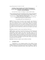
39
Figure 3.7
Nozzle of the in-house SES.
39
Figure 3.8
Structural features of the scaffold. RW: road width, FG: fill gap,
LG: layer gap, ST: slice thickness, FD: filament distance.
41
Figure 3.9
Bulk scaffold block with uniform edge after trimming off.
42
Figure 3.10 Schematic of (a) porosity calculation and (b) strand layout for
0/90º pattern.
42
Figure 3.11
SEM images of scaffolds fabricated by 0.4 mm nozzle diamer
with different dispensing speed.
48
List of figures
xviii
Figure 3.12
SEM images of some irregular dispensing at higher (12 mm/s)
dispensing speed for 0.4 mm nozzle diameter.
48
Figure 3.13
SEM images of scaffolds fabricated by 0.4 mm nozzle diamer
with different dispensing speed.
48
Figure 3.14
SEM images of some irregular dispensing at higher (18 mm/s)
dispensing speed for 0.5 mm nozzle diameter.
48
Figure 3.15
Theoretical and experimental porosity vs. dispensing speed for
different nozzle diameter.
49
Figure 3.16
Modulus vs. dispensing speed for different nozzle diameter.
51
Figure 3.17
Compressive modulus vs. porosity for different nozzle diameter.
51
Figure 3.18
SEM images of cell-scaffold construct of PCL/TCP scaffolds at
(a) day 7 and (b) day 21.
52
Figure 3.19
Confocal laser microscopy of cells within the scaffolds of
PCL/TCP at (a) day 7, (b) day 14 and (c) day 21.
52
Figure 3.20
BMSCs metabolism analysis using AlamarBlue. 53
Figure 4.1
Schematic diagram of TCP modification.
63
Figure 4.2
XPS spectra of (a) TCP and (b) TCP(Si).
64
Figure 4.3
FTIR spectra of (a) TCP and (b) TCP(Si).
64
Figure 4.4
Overview of the SES fabricated scaffolds.
65
Figure 4.5
Compressive modulus (a) and compressive strength (b) of
PCL/TCP and PCL/TCP(Si) scaffolds with various content of
GPTMS referred to TCP.
66
Figure 4.6
SEM images of (a) PCL/TCP and (b) PCL/TCP(Si) scaffolds.
67
Figure 4.7
SEM images of cell-scaffold construct of (a) PCL/TCP and (b)
PCL/TCP(Si).
68
Figure 4.8
Confocal laser microscopy with depth projection images
reconstructed from multiple horizontal images, showing 3D
distribution of cells within the scaffolds of PCL/TCP and
PCL/TCP(Si) scaffolds.
68
Figure 4.9
PicoGreen® DNA quantification results of BMSCs cultured on
PCL/TCP and PCL/TCP(Si) scaffolds.
69
Figure 4.10
mRNA expression of Cbfa1, Collagen I (Col1) and Osteocalcin 71
List of figures
xix
(OCN) of BMSCs cultured for 17 days and 24 days on PCL/TCP
and PCL/TCP(Si) scaffolds.
Figure 4.11
Protein extracts of Osteonectin (ON), Osteopontin (OPN) and
Osteocalcin (OCN) from cell-scaffold constructs after BMSCs
were cultured 31 days on PCL/TCP and PCL/TCP(Si) scaffolds.
72
Figure 4.12
Compressive modulus (a) and (b) compressive strength of
PCL/TCP and PCL/TCP(POSS) scaffolds with various content of
POSS referred to PCL/TCP composite. All POSS modified groups
are statistically significant (*p<0.05) compared to PCL/TCP
alone.
77
Figure 4.13
SEM images of (a) PCL/TCP and (b) PCL/TCP(POSS) scaffolds.
78
Figure 4.14 XPS spectra of (a) PCL/TCP and (b) PCL/TCP(POSS) scaffolds.
79
Figure 4.15 Shear viscosity vs. shear rate of PCL, PCL/TCP and
PCL/TCP(POSS) with various content of POSS referred to
PCL/TCP.
79
Figure 4.16 SEM images of cell-scaffold construct of PCL/TCP and
PCL/TCP(POSS) scaffolds at day 14 and day 21.
81
Figure 4.17 Confocal laser microscopy with depth projection images
reconstructed from multiple horizontal images shows 3D
distribution of cells within the scaffolds of PCL/TCP and
PCL/TCP(POSS).
81
Figure 4.18 PicoGreen® DNA quantification results of rat BMSCs cultured on
PCL/TCP and PCL/TCP(POSS) scaffolds (*p<0.05).
82
Figure 4.19 Alkaline phosphate expression normalized to protein content of rat
BMSC seeded PCL/TCP and PCL/TCP(POSS) scaffolds
(*p<0.05).
82
Figure 5.1 Flow diagram of the biomimetic composite coating process.
93
Figure 5.2 SEM images of (a) PCL/TCP(Si), (b) PCL/TCP(Si)-CHA and (c)
PCL/TCP(Si)-CHA-gelatin scaffolds.
93
Figure 5.3 SEM image of the cross-section of filament in (a) PCL/TCP(Si)-
CHA and (b) PCL/TCP(Si)-CHA-gelatin scaffolds.
94
Figure 5.4 ATR-FTIR specta of (a) CHA and (b) CHA-gelatin composite
coated PCL/TCP(si) film and FTIR spectra of (c) gelatin.
95
Figure 5.5 XPS spectra of (a) PCL/TCP(Si); (b) PCL/TCP(Si)-CHA and (c)
PCL/TCP(Si)-CHA-gelatin scaffolds.
96
Figure 5.6 Compression modulus (a) and compressive strength (b) of 97
List of figures
xx
PCL/TCP(Si), PCL/TCP(Si)-CHA and PCL/TCP(Si)-CHA-gelatin
scaffolds in dry and simulated physiological state.
Figure 5.7 SEM images of cell-scaffold construct of (a) PCL/TCP(Si), (b)
PCL/TCP(Si)-CHA and (c) PCL/TCP(Si)-CHA-gelatin scaffolds
at day 7. The arrow shows the cells and/or cell-sheet accumulation
that have spread on surface of the scaffolds.
98
Figure 5.8 SEM image of cell-scaffold construct of PCL/TCP(Si)-CHA-
gelatin scaffolds at day 7. The arrow shows starting of tissue
bridge formation.
99
Figure 5.9 Confocal laser microscopy with depth projection images
reconstructed from multiple horizontal images, showing 3D
distribution of cells within the scaffolds of PCL/TCP(Si),
PCL/TCP(Si)-CHA and PCL/TCP(Si)-CHA-gelatin scaffolds.
100
Figure 5.10 Confocal laser microscopy image of PCL/TCP(Si)-CHA-gelatin
scaffolds at day 10, showing tissue bridge as indicated by the
arrow.
100
Figure 5.11 PicoGreen® DNA quantification results of BMSCs cultured on
PCL/TCP(Si), PCL/TCP(Si)-CHA and PCL/TCP(Si)-CHA-gelatin
scaffolds (*p<0.05).
101
Figure 5.12 mRNA expression of Cbfa1, Collagen I (Col1) and Osteocalcin
(OCN) of BMSCs cultured for 17 days and 24 days on
PCL/TCP(Si), PCL/TCP(Si)-CHA and PCL/TCP(Si)-CHA-gelatin
scaffolds.
102
Figure 5.13 Protein extracts of Osteonectin (ON), Osteopontin (OPN) and
Osteocalcin (OCN) from cell-scaffold constructs after BMSCs
were cultured 31 days on PCL/TCP, PCL/TCP(Si), PCL/TCP(Si)-
CHA and PCL/TCP(Si)-CHA-gelatin scaffolds.
104
Figure 6.1 SEM images of overall PCL/TCP(POSS)-foam scaffolds with
porous foam structure created with different concentrations of
gelatin solution. The concentration of gelatin used was (a) 0.1%
(w/v), (b) 0.2% (w/v), (c) 0.3% (w/v), (d) 0.4% (w/v), (e) 0.5%
(w/v) and (f) 0.6% (w/v).
113
Figure 6.2 SEM images at higher magnification of PCL/TCP(POSS)-foam
scaffolds showing morphology of porous foam structure with
different concentrations of gelatin solution. The concentration of
gelatin used was (a) 0.1% (w/v), (b) 0.2% (w/v), (c) 0.3% (w/v),
(d) 0.4% (w/v), (e) 0.5% (w/v) and (f) 0.6% (w/v).
114
Figure 6.3 SEM images of PCL/TCP(POSS)-foam scaffolds (a) before and
(b) after cross-linking using EDC and NHS.
115
Figure 6.4 Photograph image of PCL/TCP(POSS)-foam scaffold (left) and 115
List of figures
xxi
PCL/TCP(POSS) scaffold (right).
Figure 6.5 SEM images of cell-scaffold construct of PCL/TCP(POSS) and
PCL/TCP(POSS)-foam scaffolds at day 14 and day 21.
116
Figure 6.6 PicoGreen® DNA quantification results of rat BMSCs cultured on
PCL/TCP(POSS) and PCL/TCP(POSS)-foam scaffolds (*p<0.05).
117
Figure 6.7 Alkaline phosphate expression normalized to protein content of rat
BMSC seeded PCL/TCP(POSS) and PCL/TCP(POSS)-foam
scaffolds (*p<0.05).
117
Figure 7.1 Confocal laser microscopy with depth projection images
reconstructed from multiple horizontal images shows 3D
distribution of cells within the scaffolds of PCL/TCP,
PCL/TCP(Si), PCL/TCP(Si)-CHA and PCL/TCP(Si)-CHA-
gelatin.
128
Figure 7.2 PicoGreen® DNA quantification results of BMSCs cultured on
PCL/TCP, PCL/TCP(Si), PCL/TCP(Si)-CHA and PCL/TCP(Si)-
CHA-gelatin scaffolds (*p<0.05).
129
Figure 7.3 Alkaline phosphatase expression normalized to protein content of
rMSC cultured on PCL/TCP, PCL/TCP(Si), PCL/TCP(Si)-CHA
and PCL/TCP(Si)-CHA-gelatin scaffolds.
130
Figure 7.4 The scull defects were drilled with a 5 mm dental drill (A), the
bone was carefully removed without damaging the dura (B) and
the scaffolds were fitted in (C).
131
Figure 7.5 The PCL/TCP-0º/90° Scaffold (A) showed more newly formed
bone matrix
compared to PCL/TCP-0º/60°/120º Scaffold (B). The PCL/TCP-
CHA-0º/90°/120º Scaffold showed the maximum bone formation
among all the groups (C), without significant differences. Picture
D, E and F showed the bone formation of the PCL/TCP-CHA-
0º/60°/120º, PCL/TCP-CHA-Gel-0º/90° Scaffold and PCL/TCP-
CHA-Gel-0º/60° Scaffold, respectively. The negative control
(empty group) showed no newly formed bone matrix (G).
132
Figure 7.6 All the experimental groups showed significantly more newly
formed bone matrix compared to the empty defect. No significant
differences could be detected between the experimental groups.
(*P < 0.05).
132
Figure 7.7 Surface analysis of PCL/TCP(Si) scaffolds with lay down pattern
of 0/º60º/120º and 0º/90º showing significant difference in (a)
porosity, (b) trabecular space, (c) scaffolds volume and (d)
scaffolds surface.
134
List of figures
xxii
Figure 7.8 A sample calvaria 12 weeks (A) is undergoing a
microcompression test. A biopsy punch was used to push-out
scaffolds to evaluate load of fracture and mechanical integration
with the host calvaria (B). Micro-compression was performed
within pore spaces of the scaffolds as well as within the empty
defect (Empty), on host calvarial bone (Bone), implant struts
(Strut), and non-bony tissue as controls (Tissue). Additionally,
push-out tests were performed on host calvarial bone as controls.
134
Figure 7.9 Micro-compression tests and push out tests were performed after
12 weeks. Stiffness (A) and Load of fracture (B) are reported here.
Regenerated tissue within the PCL/TCP-(si)-0/90°-Scaffold group
and the mPCL/TCP-(si)-CHA-0/90°- Scaffold group showed
superior stiffness and the highest push-out strength of all
experimental groups. Significant values are represented as *P <
0.05.
135
List of tables
xxiii
List of tables
Table 3.1 Porosity of scaffolds for different nozzle diameter.
47
Table 4.1. Forward primers and reverse primers used in RT-PCR.
60
Table 4.2 Thermal property of PCL/TCP(Si) composites determined by DSC
67