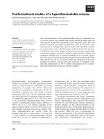
Structural studies of glycogen branching enzyme (GLGB) CRFE2alpha urucortin complexes
Bạn đang xem bản rút gọn của tài liệu. Xem và tải ngay bản đầy đủ của tài liệu tại đây (17.42 MB, 144 trang )
STRUCTURAL STUDIES OF GLYCOGEN BRANCHING
ENZYME (GLGB) AND CRFR2α:UROCORTIN COMPLEXES
KUNTAL PAL
A THESIS SUBMITTED FOR THE DEGREE OF
DOCTOR OF PHILOSOPHY
DEPARTMENT OF BIOLOGICAL SCIENCES
NATIONAL UNIVERSITY OF SINGAPORE
2010
STRUCTURAL STUDIES OF GLYCOGEN BRANCHING
ENZYME (GLGB) AND CRFR2α:UROCORTIN COMPLEXES
KUNTAL PAL
(M.Tech Biotech. And Biochem. Engg.)
A THESIS SUBMITTED FOR THE DEGREE OF
DOCTOR OF PHILOSOPHY
DEPARTMENT OF BIOLOGICAL SCIENCES
NATIONAL UNIVERSITY OF SINGAPORE
2010
To
my dear parents and teachers
“If we ask further what significance belongs to the results gained in this study of
tuberculosis it must be considered a gain for science that it has been possible for the
first credible breadth of the mycobacterial literature, but time to establish the
complete proof of the parasitic nature of a human infectious disease, and this of the
most important one. So far such proof was established only for anthrax, while in a
number of other infectious diseases in human beings, for example relapsing fever,
wound infections, leprosy, gonorrhoea, it was only known that parasites occur
simultaneously with the pathogenic process, but the causal connection between the
two has not been established. It may be expected that the elucidation of the aetiology
of tuberculosis will provide new viewpoints for the study of other infectious diseases.”
—Robert Koch, 1882
I
First of all, a heartfelt ‘Thank you’ to my family and especially, my parents and
all friends, whose continuous inspiration and moral support helped me a lot to reach my
destination.
My supervisor Dr. K. Swaminathan has been a constant source of guidance,
encouragement and support in pursuing my PhD. During the past four years he not only
provided me an opportunity to learn protein biochemistry and crystallography, but also a
level of confidence to handle a project independently. I wish to thank him for paving my
way for a good scientific future.
Next, I want to convey my special thanks to Dr. Eric H. Xu, Laboratory of
Structural Sciences, Van Andel Research Institute (VAI), Michigan for the opportunity
he gave me to work in his lab on the hCRFR2α project. His proper guidance and ideas on
every weekend meeting really helped me a lot to finish my project in limited time. I
cannot forget the help I received at the VAI lab from Drs. Augen A. Pioszak, Krishna
Vukoti and Abhisekh Bandyopadhyay, along with Jennifer and Amanda. I extend my
special thanks to Dr. Pushpa Agarwal for the collaboration on the GlgB project.
II
This is a great opportunity to say thanks to the previous lab members of Lab4 and
5. Initial help from Dileep Vaasudevan, research related support and other discussions
with Jobichen Chako, Cherlyn Ng and Rajesh Shenoy gradually trained me in performing
experiments in the proper direction. It was a great experience and pleasure to work with
them. Also, good friendship with Shiva Kumar, Vinod Roy, Sunil Tewary, Smarajit and
Soumyo, provided me a constant support throughout the four years of my PhD. Thanks to
everyone in the structural biology corridor, including Toan, Vindhya, Anupama, Feng
Xia, Kanmani, Umar, Suguna, Moorthy, Vamsi, Deepthi, Thangavelu, Manjeet,
Abhilash, Priyanka, Vivek , Kartik, Tan and Sang.
Finally, I want to thank NUS for my research scholarship, which supported my
four years of stay in Singapore and the short term attachment visit in the US and thus
helped me to pursue my research.
III
TABLE OF CONTENTS
ACKNOWLEDGEMENTS I
TABLE OF CONTENTS III
LIST OF FIGURES VI
LIST OF TABLES VII
LIST OF PUBLICATION IX
SUMMARY X
CHAPTER 1 X-RAY CRYSTALLOGRAPHY
1.1 STRUCTURAL STUDIES OF MACROMOLECULES 1
1.2 CRSYTALLOGRAPHY 2
1.2.1 The Unit Cell 2
1.2.2 Lattices,planes and indices 3
1.2.3 Symmetry operation, point groups and space groups 5
1.2.4 Bragg’s law: the condition that produces diffraction 6
1.2.5 Braggs’s law in reciprocal lattice 8
1.2.6 Ewald Sphere 9
1.3 PROTEIN CRYSTALLIZATION AND DATA COLLECTION 10
1.4 X-RAY DIFFRACTION 11
1.4.1 X-ray sources 12
1.4.2 Geometric data collection 12
1.5 DATA REDUCTION 13
1.6 WAVES, FOURIER SYNTHESIS AND FOURIER TRANSFORM 14
1.7 ELECTRON DENSITY AS FOURIER SERIES 15
1.8 PHASE PROBLEM 16
1.8.1 Patterson function 16
1.8.2 Isomorphous replacement 17
1.8.3 Direct methods 17
1.8.4 Anamolous dispersion 18
1.8.5 Molecular replacement 18
1.9 MODEL BUILDING AND REFINEMENT 20
1.9.1 Least-square methods 21
1.9.2 Molecular dynamics refinement 22
1.9.3 Additional parameters for refinement 22
1.10 IMPROVEMENT IN MAP 24
1.10.1 Solvent flattening 24
1.10.2 Extension of phases 24
IV
1.10.3 Non-crystallographic symmetry averaging 25
1.11 FINAL STRUCTURE 26
1.12 DEPOSITION OF PROTEIN STRUCTURE 26
CHAPTER 2 BIOLOGICAL SIGNIFICANCE OF GLGB
2.1 TUBERCULOSIS 30
2.2 MYCOBACTERIUM TUBERCULOSIS H37RV 31
2.3 GLYCOGEN BIOSYNTHESIS 32
2.4 α- GLUCAN 36
2.5 GLYCOGEN BRANCHING ENZYME 38
CHAPTER 3 MATERIALS AND METHODS
3.1. PROTEIN EXPRESSION AND PURIFICATION 40
3.1.1 Protein expression 40
3.1.2 Protein purification 40
3.2. X-RAY CRYSTALLOGRAPHY 41
CHAPTER 4 RESULTS AND DISCUSSION
4.1. STRUCTURE OF FULL LENGTH MYCOBACTERIUM
TUBERCULOSIS GLGB 45
4.1.1 Structural overview of WTMtbGlgB 45
4.1.2 Catalytic domain 46
4.1.3 Structural details of N1 domain 49
4.1.4 Structural alignment of WTMtbGlgB with ECΔ117GlgB 50
4.2. ENZYME ACTIVITY/KINETICS 51
4.2.1 Substrate utilization 51
4.2.2 Enzyme Inhibition 52
4.3 DISCUSSION 54
4.3.1 Influence of the N1 domain 54
4.3.2 Catalytic mechanism 54
4.3.3 Truncation mutants 55
4.3.4 Clinical significance 56
4.3.5 GlgB as a drug target 57
CHAPTER 5 BIOLOGICAL SIGNIFICANCE OF CRFR2α
5.1 G-PROTEIN COUPLED RECEPTORS AND G PROTEINS 64
5.2 CLASS B GPCRS 66
5.3 CRF PEPTIDE FAMILY 68
5.4 CORTICOTROPHIN RELEASE FACTOR RECEPTORS 70
5.5 STRUCTURAL AND FUNCTIONAL IMPLICATION 73
V
CHAPTER 6 MATERIALS AND METHODS
6.1 MOLECULAR CLONING 74
6.2 PROTEIN EXPRESSION AND PURIFICATION 75
6.3 X-RAY CRYSTALLOGRAPHY 77
6.4 ALPHA SCREEN COMPETITIVE ASSAY 79
CHAPTER 7 RESULT AND DISCUSSION
7.1 RESULTS 81
7.1.1 Expression and purification of active MBP-hCRFR2α 81
7.1.2 Selective ligand binding properties by extracellular domain of
CRFRs 83
7.1.3 Crystal structure of HCRFR2α-ECD and alignment with HCRFR1-
ECD 85
7.1.4 Crystal structure of MBP-HCRFR2α-ECD-UCN1 complex 90
7.1.5 Crystal structure of MBP-HCRFR2α-ECD in complex with UCN 2
and 3 94
7.1.6 ECD binding studies with recipocaly exchanged UCN1 and 3
mutants 97
7.2 DISCUSSION 101
7.2.1 The crystal structure of MBP-hCRFR2α-ECD 101
7.2.2 The crystal structures of MBP-hCRFR2α-ECD in complex
Urocortin 1, 2 and 3 101
7.2.3 CRF/UCN selectivity is determined by ECDs alone and Ucn1
has highest affinity 104
7.2.4 Role of structures in drug designing 106
VI
LIST OF FIGURES
Page
Figure
1.1
Seven basic unit
-cells
3
Figure 1.2
The 14 Bravais lattices
4
Figure 1.3
Miller indices of some planes in a unit
-cell
5
Figure 1.4
Bragg’s law, that
governs diffraction
7
Figure 1.5
The reciprocal lattice
9
Figure 1.6
The Ewald Sphere
9
Figure 1.7
The four
-circle diffractometer
13
Figure 2.1
The glycogen biosynthesis pathway
representing the related enzymes.
34
Figure 2.2
Formation of a
glycogen branch
35
Figure 2.3
The glucan biosynthesis pathway in prokaryotes
37
Figure 3.1
The gel filtration
and SDS-PAGE purification profile of
MtbGlgBWT using a Superdex S200 26/60 column
42
Figure 3.2
The initial crystal of GlgB
43
Figure 4.1
Structure of full length WTMtbGlgB at 2.33
Å
45
Figure 4.2
The catalytic pocket of GlgB
47
Figure 4.3
Structural details of N1 domain
50
Figure 4.4
S
uperimposition of MtbGlgB and ECΔ112GlgB
51
Figure 4.5
MtbGlgBWT
Enzyme assays and kinetic studies
53
Figure 4.6
Lineweaver
-Burke plots for MtbGlgBWT and MtbΔ108GlgB
53
Figure 4.7
Mechanism of glycogen branching
55
Figure 4.8
Sequence alignment of GlgB from pathogenic strains
60
VII
Figure 4.9
Sequence alignment between MtbGlgB and humanGlgB
63
Figure
5.1
The two domain model of interaction between class B GPCRs
68
Figure
5.2
The mammalian CRF peptide family representing CRF, Ucn1, 2
and 3 with their respective receptors CRFR1 and CRFR2
72
Figure
6.1
CRFR2αECD:Ucn1 complex crystals
77
Figure
6.2
CRFR2αECD:Ucn2 complex crystals
78
Figure
6.3
CRFR2αECD:Ucn2 complex crystals
78
Figure
7.1
Purification of functional MBP
-CRFR2α-ECD (1-117)-H
6
fusion protein
82
Figure
7.2
Differential
ligand binding properties by CRFR1 and CRFR2α
extracellular domains
84
Figure
7.3
Structure of the
hCRFR2α-ECD in the absence of ligand and
secondary structural alignment with other solved structures of
CRFR
-ECD
89
Figure
7.4
Structure of the
Urocortin1 (26-41)-NH
2
bound CRFR1 ECD at
2.75 Å resolution
93
Figure
7.5
Structure of hCRFR2α ECD, in complex with Urocortin2 (26
-
41)
-NH
2
at 2.72 Å resolution
95
Figure
7.6
Structure of CRFR1 ECD:Urocortin3 (26
-41)-NH
2
-complex at
2.49 Å resolution
97
Figure
7.7
Alascan competitive assay graphs showing the important
residues for molecular interaction
98
Figure
7.8
Alphascreen competitive assay graphs with reciprocal residual
exchange mutants of Ucn1 and Ucn3
100
Figure
7.9
Comparison of the ligand
-free and ligand-bound states of
CRFR1 and CRFR2
α
103
Figure
7.10
Binding of Ucn1/3 native and mutated peptides to the CRFR1
and CRFR2
α ECDs
105
Figure
7.11
Comparison of the CRFR2
α ECD-Ucn3 and CRFR1 ECD-CRF
complexes
108
VIII
LIST OF TABLES
Page
Table1
Details of commonly used computer programs in protein
crystal structure determination.
27
Table2
Data collection and refinement statistics for crystal structure of
GlgB.
48
Table3
Data collection and refinement details of the three crystal
structures of MBP-hCRFR2α in complex with Ucn1,2 and3.
86
Table4
Average B-factor analysis of each domain of MBP-hCRFR2α
in the asymmetric unit
109
IX
LIST OF PUBLICATION
Pal, K., Kumar, S., Sharma, S., Garg, S.K., Alam, M.S., Xu, E.H., Agrawal, P.
Swaminathan, K. (2010). Crystal structure of full length Mycobacterium tuberculosis
glycogen branching enzyme : insights of N terminal β-sandwich in substrate specificity
and enzymatic activity. J Biol Chem. 285, 20897-20903.
Pal, K., Swaminathan, K., Xu, E.H. and Pioszak, A. (2010). Structural basis for hormone
recognition by the human CRFR2α G protein-coupled receptor. J Biol Chem. 285, 40351-
40361.
X
SUMMARY
X-ray crystallography is a well renowned process for the elucidation of protein
structures involved in different cellular mechanisms and pathways.
Using X-ray protein crystallography, I have solved the glycogen branching
enzyme structure of Mycobacterium tuberculosis involved in glycogen and glucan
biosynthesis. The second structure I solved is the extracellular domain from human
corticotrophin release factor receptor 2α, which plays a role in class B GPCR based
signaling pathway.
The open reading frame Rv1326c of Mycobacterium tuberculosis (Mtb) H37Rv
encodes for an α-1,4-glucan branching enzyme (MtbGlgB, EC 2.4.1.18, Uniprot entry
Q10625). This enzyme belongs to glycoside hydrolase (GH) family 13 and catalyzes the
branching of a linear glucose chain during glycogenesis by cleaving a 1→4 bond and
making a new 1→6 bond. Here, we show the crystal structure of full-length MtbGlgB
(MtbGlgBWT) at 2.33Å resolution. MtbGlgBWT contains four domains: N1 β-sandwich,
N2 β-sandwich, a central (β/α)
8
domain that houses the catalytic site, and a C-terminal β-
sandwich. We have assayed the amylase activity with amylose and starch as substrates
and the glycogen branching activity using amylose as a substrate for MtbGlgBWT and
the N1 domain-deleted (the first 108 residues deleted) MtbΔ108GlgB protein. The N1 β-
sandwich, which is formed by the first 105 amino acids and superimposes well with the
N2 β-sandwich, is shown to have an influence in substrate binding in the amylase assay.
Also, we have checked and shown that several GH13 family inhibitors are ineffective
XI
against MtbGlgBWT and MtbΔ108GlgB. We propose a two-step reaction mechanism,
for the amylase activity (1→4 bond breakage) and isomerization (1→6 bond formation),
which occurs in the same catalytic pocket. The structural and functional properties of
MtbGlgB and MtbΔ108GlgB are compared with those of the N-terminal 112-amino acid-
deleted Escherichia coli GlgB (ECΔ112GlgB).
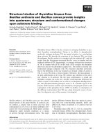
The mammalian corticotropin releasing factor (CRF)/urocortin (Ucn) peptide
hormones include four structurally similar peptides, CRF, Ucn1, Ucn2, and Ucn3, that
regulate stress responses, metabolism, and cardiovascular function by activating either of
two related class B G protein-coupled receptors, CRFR1 and CRFR2. CRF and Ucn1
activate both receptors, whereas Ucn2 and Ucn3 are CRFR2-selective. The molecular
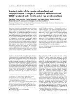
basis for selectivity is unclear. Here, we show that the purified N-terminal extracellular
domains (ECDs) of human CRFR1 and the CRFR2alpha isoform are sufficient to
discriminate the peptides, and we present three crystal structures of the CRFR2alpha
ECD bound to each of the Ucn peptides. The CRFR2alpha ECD forms the same fold
observed for the CRFR1 and mouse CRFR2beta ECDs, but contains a unique N-terminal
alpha-helix formed by its pseudo signal peptide. The CRFR2alpha ECD peptide-binding
site architecture is similar to that of CRFR1 and binding of the alpha-helical Ucn peptides
closely resembles CRF binding to CRFR1. Comparing the electrostatic surface potentials
of the ECDs suggests a charge compatibility mechanism for ligand discrimination
involving a single amino acid difference in the receptors (CRFR1 Glu104/CRFR2alpha
Pro100) at a site proximate to peptide residue 35 (Arg in CRF/Ucn1, Ala in Ucn2/3).
CRFR1 Glu104 acts as a selectivity filter preventing Ucn2/3 binding because the
nonpolar Ala35 is incompatible with the negatively charged Glu104. The structures
XII
explain the mechanisms of ligand recognition and discrimination and provide a molecular
template for the rational design of therapeutic agents selectively targeting these receptors.
Chapter 1 X-
ray crystallography
1
CHAPTER 1. X-RAY CRYSTALLOGRAPHY
1.1 STRUCTURAL STUDIES OF MACROMOLECULES
Structural studies of macromolecules are relevant to understand their physical
and chemical properties. This chapter will give an overview of the X-ray
crystallographic approach in the determination of protein structures. The importance
of X-ray crystallography as a protein structure determination technique can be
understood by the ongoing research and achievements in the last two decades.
Especially, the marvelous structures of ribosome (Wimberly et al., 2000) and
potassium channel (Doyle et al., 1998), the molecular basis of eukaryotic transcription
(Kelleher et al., 1990) with structural elucidation of the enzymatic mechanism
underlying the synthesis of adenosine triphosphate (ATP) and the discovery of an ion-
transporting enzyme by Boyer and Walker (Abrahams et al., 1994) become
milestones in the structural biology research.
The other techniques used in the field of protein structural biology are Nuclear
Magnetic Resonance (NMR) and cryo-Electron Microscopy (EM). NMR is a
wonderful technique to study the dynamics of protein structures. It has a very
important application in understanding the conformational changes that are associated
with protein-protein interaction, protein-peptide interaction and protein-small
molecules / nucleic acid interaction as beautifully explain in the case of Ca
2+
-
calmodulin system (Chou et al., 2001). But the technique has a limitation of size and
is applicable to small proteins only. On the other hand, the dynamics of a protein
when it interacts with an agonist, antagonist, partial agonist or inverse agonist is
mainly studied by X-ray crystallography (Bokoch et al., 2010). A joint application of
electron microscopy and X-ray crystallography will have broader aspects in future to
understand the molecular mechanism of huge assemblies of protein molecules in
Chapter 1 X-
ray crystallography
2
signaling pathways (Li and Thanassi, 2009). Furthermore, today high throughput
crystallography with bioinformatics analysis is providing a fundamental platform for
structure-based drug discovery in the pharmaceutical industries.
1.2 CRYSTALLOGRAPHY
Usually, the major problem in a crystallographic study is getting a diffracting
quality protein crystal. Self periodic assembly of protein molecules, with
intermolecular forces between them, leads to a crystal packing and formation of
protein crystals. In simple, a crystal is an anisotropic, homogeneous body consisting
of a three-dimensional periodic ordering of atoms, ions or molecules. The stability
and diffraction capability of these crystals depend upon the extent of the
intermolecular forces between individual molecules and contact/volume ratio.
Formation of a well ordered crystal needs proper packing of molecules in a limited
space (Chernov, 2003; Helliwell, 2005). A well formed crystal produces diffraction
images when placed in an X-ray beam. Analogous to the use of a lens in light
microscope, we use a computer to produce the view of the arrangement of atoms (real
lattice) from the diffraction images (reciprocal lattice).
1.2.1 The unit-cell
The simplest repeating unit in a crystal is known as a unit-cell (Buerger,
1966). The three dimensional crystal packing can be defined by an ordered stacking
arrangement of these unit-cells. Basically a unit-cell can be explained with three
vectors a, b and c and interaxial angles of α, β and γ, as shown in Fig. 1.1.
Chapter 1 X-
ray crystallography
3
Figure 1.1. Seven basic unit-cells. “Figure adapted from NYU Chemistry Lecture
Notes”.
A unit-cell is classified into one of seven different forms on the basis of
symmetry which is explained in Fig. 1.1. The most important thing to be noticed is
that the geometric condition of a unit-cell is not sufficient to define its associated
crystal system. For example, during data processing, be warned that a unit-cell may
have all three angles very close to 90º and yet the crystal need not belong to a system
that demands all orthogonal axes.
1.2.2 Lattices, planes and indices
If each unit-cell in a crystal is represented by a point, then the array of these
points is called a lattice. A lattice can be primitive, designated as P, when one lattice
point is present per unit-cell. However, in some cases, it is more advantageous to
encompass smaller unit-cells into a larger unit-cell, thereby enclosing more lattice
Chapter 1 X-
ray crystallography
4
points in the bigger unit-cell. The arrangement of these lattice points, in perspective of
the larger unit-cell, is called a centered lattice, designated as A for bc face centering,
B for ac face centering and C for ab face centering. If all the faces are centered, the
designation is F, and if the unit-cell body is centered, it is designated as I. The
collection of 14 possible crystallographic lattices, (Fig. 1.2) was first described by
French physicist Auguste Bravais in 1850.
Mineralogist William Hallowes Miller in 1839 introduced imaginary planes
within a unit-cell and defined them by using Miller indices. The indices hkl identify a
particular set of equivalent and parallel planes. Index h indicates the number of
Figure 1.2. The 14 Bravais lattices. “Figure adapted from Charles
Kittel, Introduction to solid state physics, 7 th ed.”.
Index h indicates the number of planes per unit-cell in the x direction while k
and l specify the planes in the y and z direction, respectively. An example is shown in
Fig. 1.3. The perpendicular distance d between adjacent lattice planes is related to the
(shortest) reciprocal lattice vector orthogonal to the planes by the equation 1.1.
Chapter 1 X-
ray crystallography
5
d = 2 / g
hkl
….(1.1)
Figure 1.3. Miller indices of some planes in a unit-cell. “Figure
adapted from NYU Chemistry Lecture Notes”.
1.2.3 Symmetry operation, point groups and space groups
Symmetry can be defined as precise and balanced operations which can
generate an identical or similar crystallographically indistinguishable image of an
object. Pseudo symmetry differs by having a copy of a similar object in place after an
operation which is not crystallographically identical. The main symmetry operation
present in a crystal system is translation, rotation and reflection along with
combination of these operations.
When a molecule moves along a, b or c of the unit-cell, translational
symmetry is applied. In the rotational symmetry operation, only rotational angles of
60, 90, 120, 180 and 360
o
are allowed. The type of rotation angle applied is
Chapter 1 X-
ray crystallography
6
represented by an integer n (n= 6, 4, 3, 2, 1, whereby n is the number of times a
molecule is rotated within 360
o
, or 360/n). Another type of rotational symmetry axis
is the screw axis, which combines rotation with the translation operation. For
example, in the two-fold screw operation, a molecule is first rotated 180
o
and then
translated half of the unit-cell length in the positive direction of the axis. Mirror and
inversion symmetry operations are not applicable to protein molecules because
applying these operations will cause the interchange of right and left handedness of
the molecule. This will warrant the presence of D-amino acids in protein molecules,
which do not exist in nature.
Point groups describe the assembly of symmetry elements without any
translation in the unit-cell. For example point group 222 (the three digits represent
operations carried out on a, b and c axis, respectively), has three 2-fold rotations, on
the a, b and c axes.
The concept of space group was first enumerated by Fyodorov (1891). Space
groups provide detailed information of 3-dimensional arrangement of molecules,
including translation, in the unit-cell. For example, space group P2
1
2
1
2 has two fold
screw operations along both the a and b axes and a two-fold rotation along the c axis.
The unit-cell arrangement in the crystal is primitive as indicated by ‘P’. In this way,
all 230 space groups, tabulated in the International Tables of Crystallography (Hahn,
1998), arise as a result of the combination of 32 point groups, 14 Bravais lattices of
the 7 lattice systems and translation symmetry (Buerger, 1956).
1.2.4 Bragg’s law: the condition that produces diffraction
Bragg’s law is a condition for diffraction by a crystal when electromagnetic
radiation of a wavelength that is comparable to atomic spacing are allowed to be
Chapter 1 X-
ray crystallography
7
incident upon a crystalline sample, scattered and undergoes a constructive
interference . For a crystalline solid, W.L. Bragg showed that a set of parallel planes
with indices hkl and interplanar spacing d
hkl
produces a diffracted beam when X-rays
of wavelength λ impinge upon the planes at an angle θ and reflected, also at the same
angle, only if θ meets the condition
2d
hkl
sinθ = nλ …. (1.2)
where n is an integer (Rhodes, 2000).
Figure 1.4. Bragg’s law, that governs diffraction. “Figure adapted from
Rhodes, 2000”.
The two planes (Fig. 1.4) represent two parallel rows of lattice points with
interplanar spacing d
hkl
. Two rays R
1
and R
2
are reflected from them at an angle θ.
Lines AC are drawn from the point of reflection A of R
1
, perpendicular to ray R
2
. If
ray R
2
is reflected at B, then the diagram shows that R
2
travels the same distance as
wave 1 plus an additional distance of 2BC. Because AB, in triangle ABC, is
perpendicular to the atomic plane, and AC is perpendicular to the incident ray, angle
CAB equals θ, the angle of incidence (two angles are equal if corresponding sides are
Chapter 1 X-
ray crystallography
8
perpendicular). Because ABC is a right-angled triangle, the sine of angle θ is BC/AB
or BC/d
hkl
. Thus BC equals d
hkl
sin θ, and the additional distance 2BC traveled by ray
R
2
is 2d
hkl
sinθ. If this difference in path length for rays reflected from successive
planes is equal to an integral number of wavelengths of the impinging X-rays
(satisfying equation 1.2), then the rays are in phase with each other, interfering
constructively to produce a strong diffracted beam. The same condition can be applied
for neutron and electron diffraction processes also.
1.2.5 Bragg’s law in reciprocal lattice
The X-ray diffraction pattern from a crystal consists of reflections (spots) in an
orderly array on film. The angle of diffraction has a simple inverse relationship with
the spacing of unit-cell in the crystalline lattice. The arrangement of reflections which
emanate from a crystal (recorded on film) is referred to as a reciprocal lattice. A
reciprocal lattice is generated as explained in Fig. 1.5. Take O as the origin in a
crystal lattice. Draw one plane for each of the sets (110), (120) and so forth, whose
interplanar distances will be d
110
, d
120
and so on, respectively. From the origin, draw a
line normal to the (110) plane. The point at a distance, 1/d
110
, on this line will define
the reciprocal lattice point 110. Do the same for (120) and so on. Thus the new points
define a lattice, with the chosen origin. This new lattice is the reciprocal lattice. If the
real unit-cell angles , and are 90, the reciprocal unit-cell has axes a* lying along
the real unit-cell edge with the corresponding length of 1/a. Similarly, the other
parameters, b* and c* are defined. If the axial lengths are expressed in Angstroms,
then the reciprocal lattice spacing is in the unit 1/Å or Å
-1
(reciprocal Angstroms).
Chapter 1 X-
ray crystallography
9
O
N
b
(110)
(120)
(130)
(010)
110
120
130
140
b*
x
y
Figure 1.5. The reciprocal lattice. “Figure adapted from Buerger, 1956”.
1.2.6 The Ewald sphere
Consider a circle of radius r, with points B and C lying on the circumference.
Figure 1.6. The Ewald Sphere. “Figure adapted from Univ. of Cambridge
lecture notes).
By trigonometry,
If this geometry is constructed in reciprocal space, then it has some important
implication. The radius can be set to 1/λ, where λ is the experimental wavelength. If O
is the (0 0 0) reciprocal lattice point, and B is a general point (h k l), then the distance