esign and fabrication of polarized ingan light emitting diodes and THz polarizer based on subwavelength metallic nanogratings
Bạn đang xem bản rút gọn của tài liệu. Xem và tải ngay bản đầy đủ của tài liệu tại đây (10.32 MB, 156 trang )
DESIGN AND FABRICATION OF POLARIZED
INGAN LIGHT-EMITTING DIODES AND THZ
POLARIZER BASED ON SUBWAVELENGTH
METALLIC NANOGRATINGS
ZHANG LIANG
(M.Sc in Physics, Wuhan University)
A THESIS SUBMITTED
FOR THE DEGREE OF DOCTOR OF PHILOSOPHY
IN ADVANCED MATERIALS FOR MICRO-AND
NANO-SYSTEMS (AMM&NS)
SINGAPORE-MIT ALLIANCE
NATIONAL UNIVERSITY OF SINGAPORE
2011
ACKNOWLEGMENTS
First of all, I would like to express my sincere appreciation to my
supervisors. Prof. Chua Soo Jin and Prof. Eugene A Fitzgerald for their
continuous supports, invaluable guidance, and encouragement throughout this
research work. They have offered me insightful ideas and suggestions and
have led me the scientific way to do research with their profound knowledge
and rich research experience. Without their help, I would not be able to
achieve this research goal.
I am also extremely grateful to Dr. Teng Jinghua and his team members
from Institute of Materials Research and Engineering (IMRE). Dr. Teng is a
very accomplished research scientist with experience of many years in the
field of solid-state lighting, and I did most of the experiments in IMRE under
his supervision.
I am greatly indebted to my senior Dr. Chen Ao, who shared with me his
valuable experience in electron beam lithography. He has also given me a lot
of helpful suggestions and encouragements during my hard period. I am also
grateful to Dr. Tan Chuan Beng, who shared with me his valuable knowledge
in photoluminance, p-n junction device physics and hydrothermal growth. I
am greatly thankful to my junior Mr. Deng Li Yuan, who has worked with me
and provided a lot of assistance to this work.
Finally, I wish to express my sincere appreciations to Prof. C.A. Ross,
Prof. C.C. Wong, Prof. C.V. Thompson and Prof. W.K. Choi for sharing their
insightful opinions and suggestions with me throughout my PhD life. I am also
thankful to the scholarship provided by SMA and to all administrative staffs.
i
Table of Contents
SUMMARY................................................................................................... I
LIST OF FIGURES ................................................................................... III
CHAPTER 1: INTRODUCTION ................................................................1
1.1 Background of the project ......................................................................1
1.1.1 Historical and state-of-the art light-emitting diode.........................1
1.1.2 Polarization of light ..........................................................................4
1.1.3 Polarization elements........................................................................5
1.1.4 Polarization of various light sources ................................................6
1.2 Motivation and objectives.......................................................................9
1.3 Organization of thesis ...........................................................................13
CHAPTER 2: THEORY AND MODELING METHOD...........................14
2.1 Introduction ..........................................................................................14
2.2 Subwavelength structure ......................................................................15
2.3 Effective medium theory.......................................................................17
2.4 Subwavelength metallic grating ...........................................................20
2.5 Numerical modeling method ................................................................24
2.5.1 Rigorous coupled-wave analysis (RCWA) .....................................26
2.5.2 Finite difference time-domain (FDTD) ..........................................30
2.6 Summary ...............................................................................................32
CHAPTER 3: FABRICATION AND CHARACTERIZATION TOOLS .33
3.1 Introduction ..........................................................................................33
3.2 Process tools ..........................................................................................33
3.2.2 Electron-beam lithography ............................................................39
3.2.3 Nanoimprint lithography ...............................................................46
3.2.4 Plasma etching ................................................................................48
3.2.4.1 Ion Milling ................................................................................49
3.2.4.2 Reactive ion etching..................................................................52
3.3 Characterization tools...........................................................................53
3.3.1 Scanning electron microscope ........................................................53
3.3.2 Atomic force microscopy ................................................................55
ii
3.3.3 Fourier transform infrared spectroscopy (FTIR) .........................59
3.3.4 Terahertz time-domain spectroscopy (THz-TDS) .........................61
3.4 Summary ...............................................................................................61
CHAPTER 4: SIMULATION AND DESIGN OF SUBWAVELENGTH
GRATING...................................................................................................62
4.1 Introduction ..........................................................................................62
4.2 Comparison of different metals ............................................................62
4.3 Effect of physical parameters of gratings ............................................67
4.3.1 Period of grating .............................................................................68
4.3.2 Duty cycle of grating.......................................................................71
4.3.3 Thickness of grating .......................................................................74
4.3.4 Angle of incidence ...........................................................................76
4.4 Field distribution of light propagating through the grating................78
4.5 Summary ...............................................................................................83
CHAPTER 5: FABRICATION AND CHARACTERIZATION OF
POLARIZED LIGHT EMITTING DIODE ..............................................84
5.1 Introduction ..........................................................................................84
5.2 Polarized InGaN LED structure ..........................................................84
5.3 Polarized InGaN LED fabrication process ..........................................86
5.4 Summary ...............................................................................................97
CHAPTER 6: FABRICATION AND CHARACTERIZATION OF
WIRE-GRID POLARIZER IN TERAHERTZ RANGE ..........................98
6.1 Introduction ..........................................................................................98
6.2 Motivation and design ..........................................................................99
6.3 Simulation on the physical parameters of grating.............................100
6.4 Fabrication of grating.........................................................................109
6.5 Characterization ................................................................................. 112
6.6 Summary ............................................................................................. 116
CHAPTER 7: SUMMARY AND FUTURE WORK ............................... 117
iii
7.1 Summary ............................................................................................. 117
7.2 Future work ........................................................................................ 118
7.3 Summary .............................................................................................125
REFERENCES .........................................................................................126
BIBLIOGRAPHY.....................................................................................140
APPENDICES ..........................................................................................141
Publication List.........................................................................................141
Journal Publications..............................................................................141
Patent .....................................................................................................142
Conference Publications........................................................................142
Conferences presentations and Awards ...................................................143
iv
Summary
Design and fabrication of polarized InGaN light-emitting
diodes and THz polarizer based on subwavelength metallic
nanogratings
InGaN light emitting diodes are poised to replace conventional light
sources for general illumination application due to their higher luminous
efficiency and long lifetime. For other applications such as in imaging, liquid
crystal backlighting and 3D display, polarized light sources would be highly
desirable.
In this work, we designed polarized InGaN LED by integrating
sub-wavelength metallic nano-grating (SMNG) fabricated on the emitting
surface. The choice of material for visible-wavelength SMNG is discussed,
and the physical parameters for SMNG are optimized. The distribution of the
electromagnetic field around the grating when light is passing through it was
investigated. These studies show a promising design of polarized InGaN LED
by using SMNG.
We have developed the process flow to make polarized InGaN LED by
integrating SMNG on the emitting surface of InGaN LED. Both device
structures and fabrication methods are compatible to conventional InGaN/GaN
LED fabrication. The process parameters for photolithography, e-beam
lithography, nanoimprint lithography, e-beam evaporation, plasma etching and
ion milling are studied and optimized.
Based on above structure design and process development, a linearly
polarized surface emitting InGaN/GaN LED on sapphire substrate was
demonstrated, with a polarization ratio of 7:1 (~88% polarization of light) for
I
electroluminescence emission from the device under electrical pumping. This
value is the highest ever reported among those achieved by other methods
such as from LEDs grown on non-polar/semi-polar surface, LEDs with
backside reflector or those incorporating photonic crystal.
Our finding suggests an effective way to make polarized light emitting
devices, without using special oriented substrate, complex design, fabrication
and packaging process. We also investigated the extension of this technology
to THz range. The performances of these subwavelength gratings in THz
ranges are characterized by THz-TDS and FTIR.
II
List of Figures
Figure 1-1 Bandgap energy versus lattice constant of III-V nitride
semiconductors at room temperature (adopted from [8]) ……………………..3
Figure 2-1 Subwavelength metallic grating geometry. The grating is periodic
along the x-axis and infinite along the y-axis………………………………...21
Figure 2-2 General behavior of SMNG. The reflected light is primarily TE
polarized, while the transmitted light is primarily TM polarized…………….22
Figure 2-3 RCWA geometry for the SMNG analyzed………………….…….26
Figure 2-4 In a Yee cell of dimension ∆x, ∆y, ∆z, note how the H field is
computed at points shifted one-half grid spacing from the E field grid points
[22]…………………………………………………………………………...31
Figure 3-1 Schematic diagram of photolithography………………………….34
Figure 3-2 SUSS Mask Aligner MA8 in IMRE…………………………..….34
Figure 3-3 Basic Recipe for photolithography used in this work. The spin
speed is 4800 rpm to achieve 1.2 um thickness AZ5214 resist. The exposure
uses i-line 365nm…………………………………………………………..…36
Figure 3-4 Photolithography parameters for photoresists used in this work…37
Figure 3-5 Microscope image showing the alignment of patterns from multiple
LED masks……………………………………………………………….…..38
Figure 3-6 Microscope image of grating patterns generated by our mask
align.T grating with 1um width (bottom) shows much lower contrast than that
with 6um width (top)…………………………………………………...…….38
Figure 3-7 Schematic diagram of a Nabity Nanometer Pattern Generation
System (NPGS) (adapted from )................................42
Figure 3-8 Equipment for e-beam lithography setup at Singapore Synchrotron
Light Source () in this work……………………………43
Figure 3-9 SEM images of various undesired patterns formed on the e-beam
resist. (a) pattern bias and non-uniformity (b) over-dosage (c) under-dose (d)
over developing time…………………………………………………………43
Figure 3-10 SEM images of uniform pattern with duty ratios (a) ½ and (b)
¾……………………………………………………………………...………44
Figure 3-11 SEM image of pattern with minimum width of 50nm. Further
III
scaling down makes the pattern distorted………………………………….....45
Figure 3-12 SEM image of uniform aluminum grating fabricated by
ion-milling process. (a) and (b) are images with different magnification for
grating period of 2um defined by photolithography. (c) and (d) the lower two
images are images with different magnification for grating period of 500 nm
defined by nanoimprint lithography……………………………………...…..51
Figure 3-13 Cross section SEM view of aluminum grating before it being
completely etched away……………………………………………………...51
Figure 3-14 Interaction between incident electrons and specimen…………..54
Figure 3-15 Schematic instrumental setup of Tapping Mode AFM [21]…….56
Figure 3-16 AFM image showing 3D surface morphology and cross section
profile of the hexagonal packed holes array fabricated by e-beam
lithography........................................................................................................58
Figure 3-17 VERTEX 80 vacuum FTIR spectrometer used in this work…....60
Figure 4-1 The real and imaginary parts of the index of refraction for
aluminum, gold and silver in visible range ……………………………….…64
Figure 4-2 Transmission efficiency calculated by RCWA for aluminum, gold
and silver grating in visible range. The dimension of sample grating used for
this calculation has a period of 150nm, grating height of 120nm and duty cycle
of 0.5.…………………………………………………………………………65
Figure 4-3 The effects of the oxide layer on the properties of an aluminum
grating. The grating parameters are same as in Figure 4-2………………..…66
Figure 4-4 Polarization performance vs. period of grating. The wire thickness
is 120 nm, the duty cycle is 50%, and it is at normal incidence. Reducing the
period increases both the transmission efficiency and extinction ratio of the
grating. ……………………………………………………………………….69
Figure 4-5 Polarization performance versus duty cycle. The grating period is
150nm, wire thickness is 120 nm, and it is at normal incidence. As the duty
cycle increases, the transmission coefficient decreases and extinction ratio
increases, and vice versa. …………………………………………………….73
Figure 4-6 Polarization performance versus grating thickness. The grating
period is 150nm, the duty cycle is 50%, and it is at normal incidence. The
extinction ratio rises with increasing thickness………………………………75
Figure 4-7 Polarization performance versus angle of incidence. The grating
period is 150nm, the duty cycle is 50%, wire thickness is 125nm, and it is at
IV
normal incidence. The polarization properties actually improve with increasing
angle of incidence θ , up to at least 45 degree, depending on the other
parameters.…………………………………………………………………………..…77
Figure 4-8 Field distribution for normal incident of TM polarization from
upper region of grating. Grating period is 150nm, grating height is 200nm…79
Figure 4-9 Field distribution for normal incident of TE polarization from upper
region of grating….……………………………………………………..……81
Figure 4-10 Field distribution for oblique incident of TM polarization from
upper region of grating…………………………………………………….…82
Figure 4-11 Phase distribution of the Ex (left) and Ey (right) field components
for oblique incident of TM polarization from upper region of grating……....83
Figure 5-1 Schematic diagram of the cross section of the polarized
InGaN/GaN green LED structure fabricated in this work……………………85
Figure 5-2 Fabrication process flow of polarized InGaN LED (15 steps in
total)… ………………………………………………………………….……88
Figure 5-3 Plot of measured GaN ICP etch depth under different etch time,
which indicates an etch rate of ~0.4um/min. ICP etching condition is: 20sccm
BCl3 and 10 sccm Cl2 under pressure of 5 mTorr at 6 °C. RIE power is 200W
and ICP power is 500W….…………………………………………..………89
Figure 5-4 Plot of deposition rate of different metals using electron-beam
evaporation with various process conditions…..……………………..………89
Figure 5-5 E-beam writing field of 300um by 300um indicated by the red square
shown under the SEM…………………………………………………...……91
Figure 5-6 SEM image of (left) uniform grating pattern across the emission
region of LED surface and (right) discontinuous grating pattern around
p-pad….………………………………………………………………………92
Figure 5-7 (a) Optical micrograph of fabricated SMNG LED mesa, where the
SMNG patterned area appears as darker in shade. (b) Scanning electron
microscope image of SMNG with a grating period of 150 nm………………93
Figure 5-8 (a) 3D AFM image of fabricated Al SMNG (b) cross section
profile….……………………………………………………………..………94
Figure 5-9 Room temperature EL spectra of the InGaN/GaN SMNG LED at a
forward injection current of 10 mA, The inset image is the optical micrograph
showing the green light emission across the mesa………..………………….95
V
Figure 5-10 EL intensity of the InGaN/GaN SMNG LED as a function of the
polarizer angle within one period. Dots are measured at 5-degree intervals
while the red curve is simulated by RCWA also with 5-degree intervals but
connected as a continuous curve. The inset image shows an optical micrograph
of the eclipse like light emission around the p-pad when the polarizer angle is
placed at extinction position………….………………………………………97
Figure 6-1 Simulation results of (a) extinction ratio and (b) insertion loss of Al
wire-grid polarizer with period of 500 nm and 3 um as a function of terahertz
frequencies under normal incidence. Al thickness used in this simulation is
120nm………….………………………………………………..……..……102
Figure 6-2 Simulation results of TE and TM transmittances at normal incident
angle as a function of terahertz frequencies…………………………...……103
Figure 6-3 FDTD simulation on (a) transmittance of TM wave and (b)
extinction ratio in 0~5 THz region with different metal thicknesses, while the
duty cycle and grating period were fixed at 50% and 500nm,
respectively.....................................................................................................105
Figure 6-4 FDTD simulation on (a) transmittance of TM wave and (b)
extinction ratio in 0~5 THz region with different grating period, while the duty
cycle and metal thickness were fixed at 50% and 500nm, respectively…….106
Figure 6-5 FDTD simulation on (a) transmittance of TM wave and (b)
extinction ratio in 0~5T THz region with different duty cycle, while both the
grating period and metal thickness were fixed at 500nm………………...…107
Figure 6-6 FDTD simulation on extinction ratio at 1 THz with different
thickness of substrate. Metal thickness is 200 nm and grating period is
500nm…..…………………………………………………………………...108
Figure 6-7 Process flow for the grating fabrication…..……………..………110
Figure 6-8 SEM image of the fabricated wire-grid polarizer with a period of
500nm……………………………….…………………………...………….110
Figure 6-9 (a) Grating on photoresist with 2um period defined by conventional
photolithography. The sample is exposed under UV light for 700 mw/cm2 for
10 sec and then developed with diluted developer (1:1 with DI water) for
12sec. (b) SEM image of Au grating with period of 2um after lift-off…..111
Figure 6-10 Lift-off process of Au grating with 2um period. The substrate
could be Si or quartz……………..……………………………………….…111
Figure 6-11 Measured THz spectrum using FTIR for the fabricated wire-grid
polarizer with a period of 500nm by nanoimprint lithography and wet etching
process…………….……………………………………………………...…113
VI
Figure 6-12 Measured THz spectrum using FTIR for the fabricated wire-grid
polarizer with a period of 2um by photolithography and lift-off process…...114
Figure 6-13 (a) THz-TDs testing raw data showing that signal of TM is exactly
the same as bare Si and the signal of TE is much smaller than TM. (b) The
frequency response of the sample to TE and TM wave extracted by performing
Fourier transformation. (c) The corresponding extinction ratio spectrum….116
Figure 7-1 Cross section view (left) and top view (right) of the polarized LED
with SMNG directly on top of the p-GaN layer……….……………………119
Figure 7-2 Cross section view (left) and top view (right) of the polarized
SMNG LED having dicing trench etched and coated with reflecting
metals………………………………………………………………………..120
Figure 7-3 Cross section diagram of flip-chip LED with SWMG made on
sapphire substrate (left) and a membrane LED with SMNG made on N-GaN
(right)…………….. ………………………………………………………...121
Figure 7-4 Microscope image surface of Cu after electroplating…………...122
Figure 7-5 SEM image of surface morphology of Cu after electroplating,
where the grain boundary of Cu is shown…………………………………..122
Figure 7-6 SEM image showing the undercut microdisk LED structure…...123
Figure 7-7 PL measurement of undercut GaN microdisk on Si substrate…..124
VII
Chapter 1: Introduction
1.1 Background of the project
1.1.1 Historical and state-of-the art light-emitting diode
Perhaps one of the most widely used technologies is the light emitting
diode (LED), which is applied in an extremely broad range of markets and
applications. LEDs with low output powers are used for indicator lighting on
computers, laptops or televisions and also for bright outdoor displays. LEDs
with high output powers are used in traffic signals and automotive headlights,
projection display and indoor and outdoor illumination. LEDs are also used to
backlit buttons or keypads on cellular telephones, and liquid crystal display
(LCD) screens. These applications have lead to major growth of LED market
in recent years.
LED is basically an electrical diode consisting of an n-type semiconductor
and a p-type semiconductor forming a junction. Due to the difference in
electron and hole concentration on the two sides of the junction, the diffusion
of electrons and holes results in regions with net charge, across which there is
an electric field. This electric field induces a drift current of electrons and
holes, which exactly offsets diffusion currents at equilibrium, and there is no
net current flowing through the diode. When a positive voltage is applied to
the p-type side, the electric field and the drift current are reduced, thus the
diffusion current overwhelms drift current, making electrons and holes
injected into the other side and recombined with each other. Being direct
bandgap, the distinguishing feature of an LED is that the recombination is
radiative and releases energy in the form of light, usually as one particular
1
color.
LEDs were discovered by accident early in the last century and the first
LED results were published in 1907. LEDs became forgotten and only to be
re-discovered later in the 1920s and again in the 1950s. In the 1960s, several
groups pursued the demonstration of semiconductor lasers. The first applicable
LEDs were by-products in this pursuit. During the last 40 years, progress in
the field of LEDs has been breathtaking.
The InGaN material system was developed in the early 1990s and has
become commercially available in the late 1990s. A name that is closely
associated with GaN LEDs and lasers is the Nichia Chemical Industries
Corporation, Japan. A team of researchers that included Shuji Nakamura has
made lots of contributions to the development of GaN LEDs [1-7].
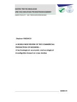
The bandgap energy versus the lattice constant in the nitride material
family is shown in Figure 1. Inspection of the figure indicates that InGaN is
suitable for covering the entire visible spectrum. To date InGaN is the primary
material system for high-brightness ultraviolet (UV), blue, green and white
LEDs.
State-of-the art LEDs are bright, efficient, small, and reliable. In contrast
to many other light sources, LEDs have the potential of converting electricity
to light with near-unity efficiency. Besides high efficiency and power, a key
benefit provided by LEDs is the ability to tune properties such as wavelength
or color temperature of emission to meet the needs of specific applications.
This flexibility allows the LED to service a wider variety of markets than any
other light source. Indeed, they are already widely used in computers,
2
television sets and other consumer electronics, and are becoming a market
leader for outdoor applications such as traffic lights and indicator lights on
cars. The story of LEDs is still in progress. Great technological advances will
surely continue to be made. Philips and other big companies are investing
heavily to help LED technology to evolve rapidly. As a result, it is expected
that LEDs will play an increasingly important role as light sources and will
become the dominant light source in the future.
Figure 1-1 Bandgap energy versus lattice constant of III-V nitride
semiconductors at room temperature (adopted from [8])
3
1.1.2 Polarization of light
Polarization is a property which describes the orientation of oscillations
for certain types of waves. Electromagnetic waves such as light, exhibits
polarization, while acoustic waves in a gas or liquid do not have polarization,
since the direction of vibration is same as the direction of propagation.
By convention, the polarization of light is described as the orientation of
the wave's electric field. When light is traveling in free space, in most cases it
propagates as a transverse wave, where the polarization is perpendicular to the
wave's direction of travel. In this case, the electric field may be oriented in a
single direction, so called linear polarization; or it may rotate during travelling,
so called circular or elliptical polarization. The description of the wave's
polarization can be complex for instance in a waveguide or the radically
polarized beams in free space, as the fields can have longitudinal as well as
transverse components [9].
The polarization state of light is one important property. Natural processes
including magnetic fields, mechanical stresses, and chemical reactions can
affected the polarization of light. Measuring the change of polarization can
give valuable information about these processes. Polarized light can have
many commercial applications, ranging from simple devices such as polarized
sunglasses to complicated liquid-crystal displays (LCDs). It can also be used
in theaters to project 3-D movies.
4
1.1.3 Polarization elements
Natural light is unpolarized by having its electric field symmetrically
orientated. All polarization elements work because of certain form of
asymmetry. This asymmetry gives rise to the different polarized waves.
Different processes can be used to polarize light, including dichroism,
reflection, birefringence, and scattering. Dichroism refers to the selective
absorption of one polarizations. Light reflected at the Brewster’s angle is
completely polarized parallel to the plane of surface. Brewster’s angle θ B is
defined by tan θ B = nt / ni , where nt is the index of the transmitted medium
and ni is the index of the incident medium. Birefringence is a property of
certain crystalline materials, such as calcite, where different polarizations see
different indices of refraction in the material. This will cause the two
polarizations to travel different paths through the material, e.g. Wollaston
polarizing prisms.
Finally, scattering from a molecule can also polarize light
because of the dipole field created by the excited molecule.
One type of birefringent polarizer is the wire-grid polarizer [9] where the
asymmetry is due to the wires. The earliest documented wire-gird polarizer
was produced by Heinrich Hertz in 1888 when he used it to test the properties
of the newly discovered radio wave. Since then, the grating period of wire-grid
polarizer has been scaled down, and successfully applied to the microwave
and infrared regions, and more recently used as polarized beam splitter in
optical communication.
5
1.1.4 Polarization of various light sources
Most of the electromagnetic radiation sources contain a large number of
atoms or molecules that emit light. The orientation of the electric fields
produced by these emitters may not be correlated, thus light is unpolarized.
In many cases, the output of a laser is polarized, where the electric field
oscillates in a certain direction perpendicular to the propagation direction of
the laser beam. Gas lasers typically use a window tilted at Brewster's angle to
allow the beam to leave the laser tube. Since the window reflects some
s-polarized light but no p-polarized light, the gain for the s-polarization is
reduced but that for the p-polarization is not affected. This causes the laser's
output to be p-polarized [9]. Some laser light is more polarized than gas lasers,
e.g. Nd:YAGs are highly linearly polarized. Diode lasers are much less and
may even be elliptically polarized. VCSELs can have very non-classical states,
like radial and tangential polarization.
As a part of the development of solid-state lighting technology, the
polarization of light emitted from LED has also been studied for long a time.
Nonpolar m-plane (1010) GaN film growth was demonstrated on m-plane SiC
substrates in 1996 by Horino et al [10–12]. Although the predominant aim of
this study was wafer cleaving for laser cavity fabrication since the
conventional c-plane sapphire wafers do not cleave, in-plane anisotropic
photoluminescence (PL) was demonstrated. At about the same time, from the
theoretical aspect, the electronic band structure of GaN was studied. The
effective-mass Hamiltonian for wurtzite semiconductors was derived,
6
including the strain effects, which provides a theoretical groundwork for
calculating the electronic band structures and optical constants of bulk and
quantum-well wurtzite semiconductors [13]. The effect of uniaxial stress on
photoluminescence in GaN and stimulated emission in InGaN/GaN multiple
quantum wells was also studied [14]. Furthermore, optical gains in
wurtzite–GaN strained quantum-well (QW) lasers were theoretically estimated
for various crystallographic directions [15, 16]. For the experimental aspects,
the optical anisotropy of excitons in strained GaN epilayers grown along the
<1010> direction [17] and polarized photoluminescence study of free and
bound excitons in free-standing GaN [18] were investigated. In 2000, the
advantage of the nonpolar planes was shown by the quantum well structure
[19], which demonstrated that the epitaxial growth of GaN/(Al,Ga)N in a
non-polar direction allows the fabrication of structures free of electrostatic
fields, resulting in an improved quantum efficiency. Later, optical polarization
characteristics were studied on such quantum wells via photoluminescence
[20-22], which showed a strong in-plane optical anisotropy. Several reports on
hetero-epitaxially grown nonpolar LEDs appeared in the year 2003 to 2004
[23–25]. In 2005, Gardner et al. reported electroluminescence (EL) anisotropy
on their m-plane LEDs fabricated on m-plane SiC substrates [26]. UCSB
nitride group followed by reporting on semipolar LEDs [27–29]. Despite this
interesting polarized light emission property, research stagnated because of
inferior material quality and low optical output power. Moreover, even though
GaN-based LEDs grown on non-polar or semi-polar crystal planes emit some
polarized light, growth in these directions is challenging, and very high quality
7
bulk GaN substrates have to be used to achieve acceptable light output
intensity. These substrates are typically very small and expensive, which
makes the commercial application of non-polar or semi-polar growth currently
unfeasible. Instead, commercial efforts are focused on conventional polar
c-plane LEDs, which have generally been assumed to be unpolarized.
8
1.2 Motivation and objectives
Since early this year, the movie “Avatar” has attracted a lot of interest on
3D movie and 3D display. Creating the illusion of 3 dimensions relies entirely
on the fact that we have two eyes separated by a particular distance. If each
eye is shown the same image shot from slightly different angles then when our
brain combines the images, the resulting image will appear 3D. This is the
principle that all 3D effects use. In 3D movies and pictures, there are two
images, one for each eye. The positions of objects in the images are more or
slightly different depending on how deep they are in the picture. These
difference forces the eyes to change their angle to merge the two images. In
most 3D movie theaters, the two images are projected onto the screen by light
waves whose polarizations are altered by a polarized filter. The glasses the
viewer wears have differently polarized lenses, which allow incoming light to
pass if light polarized in same direction as the lens, and filter it completely if it
is polarized with a 90 degree angle difference. This allows only the correct
image to be seen by each eye of the viewer. While it works fine in 3D theater,
is it possible that we watch 3D movie at home simply with our laptop? Since
there is no way to similarly create two polarized images by projecting through
polarized filter, we need the light source which powers laptop screen to be
polarized, namely a polarized visible LED.
In addition to this simple example, polarized light emission attracts
attention for general display applications as well [30-34]. It is considered to be
a great advantage in using LEDs as liquid crystal display (LCD) backlighting
in computer monitors and mobile phone screens, since the operation principle
9
of LCDs inherently relies on linearly polarized light. Besides to be extremely
useful for LCD backlighting, LEDs that emit polarized light would be highly
desirable for many applications, including sensing, imaging [35,36], and
communication [37] based on optical polarization-multiplexing.
Thus, the non-polar or semi-polar InGaN growth has been aggressively
pursued since such growth for LED structures leads to partially polarized
output. Comparatively little attention has been paid to the emission
characteristics by state-of-the-art LEDs grown on polar substrates, which is
actually the most commonly used in the market due to their high efficiency,
power and long lifetime. It has been reported that light emitted in certain
directions shows some degree of polarization [38]. Although valence band
intermixing can result a dominant polarization along quantum well plane, it
only emits from the edge of unpackaged LED chips [39], and hence with
limited application. Moreover, this inherent polarization effect is eliminated by
rotationally symmetric structures of LED packaging because their act to
average the light rays emitted in different directions. More recently, the
viability of the polarized light source concept based on conventional c-plane
GaN-based LEDs has been proven following the demonstration of polarized
light emission by c-plane LEDs and the polarization enhancing reflector and
encapsulation concept [40-42].
The basic idea of this design takes advantage
of the low reflection coefficient for transverse magnetic polarized light near
Brewster’s angle, so as to enhance extraction of a particular desired linear
polarization from an unpolarized source. However, it is clear that when the
concept behind the polarization-enhancing encapsulation is applied to
10
real-world sources such as LEDs – which may have different emission patterns
–the optimum shape may be different. The largest enhancement of polarization
is achieved only when the encapsulation shape is matched specifically to the
emission pattern of the encapsulated light source. As a result, complex design,
fabrication and packaging process are involved, and the resulting polarization
ratio is only up to 3.5 : 1. High polarization ratios light emitting sources will
be a requirement if replacement of the polarizing films in conventional LCDs
is to be achieved. Moreover, the space occupied by the reflector as designed in
[40] also adds additional limit on the application of such polarized light
emitter. Miniaturization and refinement to make this device that is similar in
size to currently commercial LED is a major challenge of this technology.
Despite these problems, companies still expressed great interest for the
polarized LEDs, which gives great motivation to continue this research. Faced
with the difficulty of a bottom reflector approach, we are forced to work on the
surface. The easiest approach is to directly place conventional polarization
elements onto the LED. Unfortunately, conventional high quality polarizer
such as birefringent crystal has similar problem as the above-mentioned
reflector due to its large dimension, e.g the Wollaston polarizing prisms. It is
hardly possible to place a thin film of birefringent crystal on the LED surface
with a size to matching to the die while leaving two electrodes uncovered for
external connection.
Another idea is the integration of a wire-grid polarizer on the LED surface.
Since the key element of wire-grid polarizer is the metallic grating whose
dimension is scalable, the concept is theoretically applicable to LED in the
11
visible regime. Moreover, compared with the other polarization elements, a
noticeable advantage of wire-grid polarizers is that their fabrication process is
compatible with that of solid-state diodes, which makes it possible to integrate
them for solid-state lighting. Finally, the polarization properties can be tailored
for specific applications by changing the physical parameters of the gratings,
which is a feature not available with other types of polarization elements. And
it is thought that this tight integration may give rise to high polarization ratios.
Hence, we are motivated to investigate the development of metallic grating
integrated on InGaN LED for polarized emission
12
1.3 Organization of thesis
The subject of this thesis is to develop polarized LED by integrating
subwavelength metallic nanograting to InGaN LED. Meanwhile, the
polarization response of the subwavelength metallic grating extended to the
terahertz wave is also studied.
In Chapter 2, the theory and basic optical properties of subwavelength
metallic grating will be presented. Numerical schemes for the simulation used
in this thesis will be briefly introduced.
In Chapter 3, the main experimental tools used in this project will be
introduced, including photolithography, e-beam lithography, nanoimprint
lithography, plasma etching, atomic force microscopy, Fourier transform
infrared spectroscopy and terahertz time-domain spectroscopy.
In Chapter 4, simulations are performed to model the performance of
subwavelength grating. The choice of grating material for application in the
visible-wavelength range and how the changes in the physical parameters of
the grating affect its polarization properties are studied in details.
In Chapter 5, the process flow for fabricating the polarized LED is
discussed in details. The fabricated device is electrically pumped and
characterized, where the EL emission shows a high degree of polarization.
In Chapter 6, the polarization response of the subwavelength metallic
grating extended to the terahertz wave is studied by simulation. The
fabrication and characterization of the gratings are presented. Results show
that subwavelength gratings are also applicable for polarizing THz waves.
The whole thesis will be summarized in Chapter 7.
13