Characterization of interfacial mechanical properties using wedge indentation method 1
Bạn đang xem bản rút gọn của tài liệu. Xem và tải ngay bản đầy đủ của tài liệu tại đây (3.55 MB, 89 trang )
CHARACTERIZATION OF INTERFACIAL
MECHANICAL PROPERTIES USING WEDGE
INDENTATION METHOD
YEAP KONG BOON
NATIONAL UNIVERSITY OF SINGAPORE
2010
CHARACTERIZATION OF INTERFACIAL
MECHANICAL PROPERTIES USING WEDGE
INDENTATION METHOD
YEAP KONG BOON
(B. Eng. (Hons.), University Technology Malaysia)
A THESIS SUBMITTED
FOR THE DEGREE OF DOCTOR OF PHILOSOPHY
DEPARTMENT OF MECHANICAL ENGINEERING
NATIONAL UNIVERSITY OF SINGAPORE
2010
i
Preface
This dissertation is submitted for the degree of Doctor of Philosophy in the
Department of Mechanical Engineering, National University of Singapore (NUS)
under the supervision of Associate Professor, Dr. Zeng Kaiyang. Part of the research
works have been conducted at Institute of Materials Research and Engineering,
Singapore (IMRE). To the best knowledge of the author, all of the results presented in
this dissertation are original, and references are provided to the works by other
researchers. The majority portions of this dissertation have been published or
submitted to international journals or presented at various international conferences as
listed below:
Journal Papers:
1. K. B. Yeap, K. Zeng, H. Jiang, L. Shen and D. Chi, Determining Interfacial
Properties of Submicron Low-k Films on Si Substrate by using Wedge
Indentation Technique, Journal of Applied Physics, 101, 123531 (2007).
2. K.B. Yeap, K.Y. Zeng and D.Z. Chi, Determining the Interfacial Toughness of
Low-k Films on Si Substrate by Wedge Indentation: Further Studies, Acta
Materialia, 56, p.977-984 (2008).
3. K.B. Yeap, K.Y. Zeng and D.Z. Chi, Wedge Indentation Studies of Low-k
Films at Inert, Water and Ambient Environments, Materials Science and
Engineering A-Structural Materials Properties Microstructure and Processing,
518, p.132-138 (2009).
4. L. Chen, K.B. Yeap, K.Y. Zeng and G.R. Liu, Finite Element Simulation and
Experimental Determination of Interfacial Adhesion Properties by Wedge
Indentation, 89, p. 1395-1413 (2009).
Contributions: Providing nanoindentation experimental supports, involvement
in discussions and making comparison of the experimental and simulation
results.
ii
5. J. Zhu, K.B. Yeap, K.Y. Zeng and L. Lu, Mechanical and Interfacial Properties
of Sputtered Ruo
2
Thin Film on Si Substrate for Solid State Electronic Devices.
Submitted to Thin Solid Film for review.
Contributions: Providing nanoindentation experimental supports and
involvement in discussions.
Book Chapter:
1. K.Y. Zeng, K.B. Yeap, A. Kumar, L. Chen and H.Y. Jiang, Fracture
Toughness and Interfacial Adhesion Strength of Thin Films: Indentation and
Scratch Experiments and Analysis, to be published in CRC Handbook of
Nano-structured Thin Films and Coatings (Three Volume Set), Vol. 1, Chapter
3, Ed. S.Zhang, CRC Press (2010).
Conference Presentations:
1. K. B. Yeap, K. Zeng, L. Shen and D. Chi, Determining the Interfacial
Properties of Low-k Film by Wedge Nanoindentation, Materials Tri-
Conference: Thin Film 2006, Singapore (Presented by Kong Boon Yeap).
2. K.B. Yeap, L. Chen, K.Y. Zeng, and D.Z. Chi, A Simple Method to Quantify
Interfacial Mechanical Properties of Low-k /Si: Wedge Indentation Technique,
MRS Spring 2009, California, USA (Presented by Kong Boon Yeap).
3. K.B. Yeap and K.Y. Zeng, A Simple Method to Quantify Interfacial
Mechanical Properties of Low-k /Si: Wedge Indentation Technique, ICMAT
2009, Singapore (Presented by Kong Boon Yeap).
4. K. B. Yeap and K.Y. Zeng, Determination of Interfacial Mechanical and Time-
dependent Properties of Low-k Films by Wedge Indentation Method,
Advanced Materials Workshop 2009, Cottbus, Germany (Presented by Kong
Boon Yeap).
5. K.B. Yeap, K.Y. Zeng, R. Yvonne and E. Zschech, Determining Cohesive
Toughness and Adhesion of Low-k Film by Nanoindentation, 11
th
Stress
Workshop 2010, Dresden, Germany (Presented by Kong Boon Yeap).
iii
Acknowledgements
First of all, I would like to express my sincere gratitude to my supervisors,
Associate Prof. Dr. Zeng Kaiyang and Dr. Chi Dongzhi, for their guidance,
supervision, encouragement and advice during the course of my Ph.D. study. The
scientific methods and research skills imparted by them are the most valuable gift for
my future research career in the field of “Nanomechanics of Materials”.
Also, I would like to thank the research staffs in the Institute of Materials
Research and Engineering (IMRE) and the National University of Singapore (NUS). I
especially thank Ms. Shen Lu (IMRE) for the help on conducting the nanoindentation
experiments and Madam Zhong Xiangli (NUS) for the help on operating the focused-
ion-beam system. In addition, I would like to thank my room mates, laboratory
colleagues and friends for their support and help.
Finally, I owed many thanks to my girl friend and my family for their love,
patience, support and encouragement, without that I would not be able to complete this
Ph.D. thesis.
iv
Table of Contents
Preface
i
Acknowledgements
iii
Table of Contents
iv
Summary
viii
List of Tables
x
List of Figures
xii
List of Symbols
xix
Chapter 1: Introduction
1
1.1 Overview of the Interfacial Toughness Characterization
Methods
2
1.2 Background of Low-k Thin Films 3
1.3 Research Objectives and Significance 6
1.4 Thesis Outline 10
Reference
11
Chapter 2: Literature Review
14
2.1 Relationships between Interfacial Delaminations and
Nanoindentation Load-Penetration Curves
15
2.2 Indentation Methods Developed to Determine the Interfacial
Toughness of Thin Film/Substrate Structure
16
2.2.1 Conical Indentation 19
2.2.2 Microwedge Indentation of Line Structure 23
2.2.3 Wedge Indentation on the Systems with Strong
Interfaces
27
v
2.3 Area under Indentation Load-Penetration Curve and Work of
Fracture
31
2.4 Mechanical Aspects and Reliability of Low-k Films 33
2.4.1 Interfacial Fracture of Low-k Films 36
2.4.2 Time-Dependent Fracture of Low-k Films 39
Reference
45
Chapter 3: Experiment Methodology
49
3.1 Sample Materials 49
3.2 Nanoindentation Experiments 51
3.2.1 Elastic Modulus and Hardness Characterization 53
3.2.2 Interfacial Toughness Characterization 55
3.2.3 Time-Dependent Fracture Properties Characterization 56
3.3 Crack Profile Characterization 57
3.3.1 Plane View Imaging of Indentation Impressions 58
3.3.2 Cross-Sectional Imaging of Indentation Impressions 59
3.3.3 Chemical Analysis of Fracture Surfaces 61
Reference
62
Chapter 4: Development of Wedge Indentation Method to
Characterize the Interfacial Toughness of Sub-Micron
Low-Dielectric (k) Thin Films
63
4.1 Correlations between the Nanoindentation P-h curves and
the Fracture Processes
64
4.1.1 The Correlation Studies on the MSQ/Si System 65
4.1.2 The Correlation Studies on the BD/Si System 75
4.2 Mechanics of Interfacial Adhesion 78
4.3 Curvature of the Crack Front 88
vi
4.4 Determination of Interfacial Adhesion 94
4.4.1 Elastic Modulus and Hardness 95
4.4.2 MSQ film on Si Substrate 97
4.4.3 BD films on Si Substrate 101
4.4.4 Chemical Analysis to Confirm the Delamination
Crack Path
111
4.4.5 Work of Indentation and Fracture Energy 112
4.5 Conclusion 118
Reference
120
Chapter 5: Comparison of the Finite Element Simulation and
Experiments of Wedge Indentation Test
123
5.1 Elastic-Plastic Properties of BD and MSQ films 124
5.2 Interfacial Adhesion Energy and Strength 128
5.2.1 BD films on Si Substrate 129
5.2.2 MSQ film on Si Substrate 131
5.3 Conclusion 134
Reference
135
Chapter 6: Wedge Indentation Studies of Low-k Films at Inert,
Water and Ambient Environments
136
6.1 Time-Dependent Fracture during Wedge Indentation Tests 139
6.2 Lifetime and Loading-Rate Analysis 147
6.3 Influences of Test Environments on Fracture Processes 151
6.4 Crack Growth at Inert Environment 155
6.5 Conclusion 156
Reference 158
vii
Chapter 7: Wedge Indentations on Hard-Film-Soft-Substrate System
160
7.1 Correlation Study on RuO
2
/Si System 161
7.2 Interfacial Toughness of RuO
2
/Si System 164
7.3 Conclusion 168
Reference
170
Chapter 8: Summary, Conclusions and Recommendations
171
8.1 Interfacial Toughness 171
8.2 Time-dependent Fracture 173
8.3 Wedge Indentation on Multilayer 175
8.4 Hard-Film-on-Soft-Substrate 178
8.5 Other Avenues for Future Works
179
Appendix A: Schematic Diagram of a FIB Cutting on Wedge
Indentation Impression
183
Appendix B: Generalization of Indentation Induced Stress
184
Appendix C: EDX results
186
Appendix D: FEM simulation and model for Wedge Indentation
Induced Delamination
195
viii
Summary
Shrinkage of device dimensions in microprocessors and micro-electro-
mechanical systems to nanometer scale has brought major concerns on the device
reliability and the material compatibility with existing fabrication processes. A vast
amount of work has been dedicated to understand and enhance the mechanical
properties of this nanometer structure, e.g. elastic modulus, cohesive toughness and
interfacial adhesion. However, the mechanics of interfacial adhesion is a rather
complicated subject. This thesis develops a simple way to measure the interfacial
adhesion of thin film/substrate structure using the wedge indentation method. We
intend to simplify the existing indentation experimental procedures and analytical
solutions, so that the measurement of interfacial adhesion is simple enough for
scientists and engineers who may have little experience in this area.
The development of a new wedge indentation experiment to characterize
interfacial adhesion can be divided into three parts. In the first part, the correlation
between the cracking sequence and indentation load-penetration curve (indentation-
fracture correlation) is established. In the second part, based on the indentation-
fracture correlation, a simple experiment and analysis procedure is developed to
measure the interfacial adhesion of thin film/substrate structures. In the third part, the
experiment is conducted on low-k/Si systems (e.g. BlackDiamond™ (BD/Si) and
methyl-silsesquioxane (MSQ/Si)) and RuO
2
/Si system to verify the accuracy of the
interfacial adhesion measured using the simple analysis procedure.
ix
To further confirm the validity of the analysis procedure, finite-element
modeling (FEM) of the wedge indentation induced delamination is conducted in a
collaborative study. The results from wedge indentation experiments are compared
with the predictions from FEM simulations in two aspects. Firstly, the plastic
properties (e.g. yield strength and strain hardening exponent) of the thin film/substrate
structure are determined by matching the load-penetration (P-h) curves from
experiment and simulation. Secondly, the interfacial energy and the interfacial strength
of the BD/Si and the MSQ/Si systems are determined by plotting the experimentally
obtained critical indentation loads for interfacial separations into the contour plots
derived from FEM simulations – the interfacial energy-strength contour.
The understanding of the role of environment on the degradation of mechanical
properties is crucial for long-term device reliability and fabrication processes
compatibility. During the wedge indentation experiments on the low-k films, time-
dependent fractures can be observed, when a prolong holding at maximum load or a
slow loading rate is applied. Qualitative evaluations are therefore conducted to
examine the time-dependent fracture behavior of the low-k films under different
environmental conditions, e.g. water, ambient and inert conditions.
x
List of Tables
Table 1.1 The technology roadmap for interconnects in a microprocessor device.
Table 2.1 Selected properties of the low-k dielectrics (MSQ and OSG) and the
conventional SiO
2
dielectric.
Table 3.1 The MSQ and BD films used in this study.
Table 3.2 MTS Nanoindenter XP
®
system specifications.
Table 3.3 UMIS-2000H
®
system specifications.
Table 3.4 FIB cutting parameters for the MSQ, BD and RuO
2
films
Table 4.1 Indentation load and plastic depth that are associated with the crack
profiles induced by the wedge and the Berkovich indentations on the
MSQ/Si system.
Table 4.2 Curvature of crack front and the dimensionless constant determined
for the BD Films with different thickness.
Table 4.3 Elastic modulus and hardness for the MSQ and the BD films
Table 4.4 The calculation of interfacial toughness and key parameters for the
MSQ/Si system. Note: (1) The average long axis lengths, 2b’ are 5.63
µm and 6.61 µm, for 90° and 120° wedge indentations, respectively.
(2) Maximum Loads, P
max
for 90° and 120° wedge tip indentations are
9 mN and 15 mN, respectively.
Table 4.5 The calculation of interfacial toughness for the BD/Si system. Note:
(1) Data are averaged from 15 indentation impressions. (2) The
indentation plastic depth is determined from an indentation load-
penetration curve averaged from 15 indentations.
xi
Table 4.6 The interfacial crack front’s stress-strain condition and the interfacial
toughness of the BD/Si systems. Notes: (a) Errors represent the
standard deviations from 15 data sets. (b) The wedge indenter lengths,
l are 4.06 µm and 7.24 µm.
Table 4.7 The fracture toughness (film and interfacial toughness) of the BD/Si
system and the interfacial toughness of the MSQ/Si system calculated
following Malzbender’s method, Li’s method and modified Li’s
method.
Table 5.1 Elastic-plastic properties of the 500 nm thick BD film and the 400 nm
thick MSQ film. Note: Yield strength and strain hardening in these
given range could fit the simulation and the experimentally obtained
P-h curve very well.
Table 6.1 The slopes and time for the stages of h-t curve of holding test done on
BD/Si system at (a) ambient environment, (b) inert environment, and
(c) watered environment [9]. Note: All the data above are averaged
from 40 sets of load-holding tests with P
max
= 6mN, or ε = 0.8. The
errors are standard deviations of the data.
Table 7.1 Calculations of the interfacial toughness of the RuO
2
/Si system (90°
wedge indentation). Notes: (a) The average value of the long axis
length, 2b’ is 5.0μm. (b) The critical buckling stress for the straight-
sided buckle is applied.
Table 7.2 Calculations of the interfacial toughness of the RuO
2
/Si system (120°
wedge indentation). Notes: (a) The average value of the long axis
length, 2b’ is 6.6μm. (b) The critical buckling stress for the straight-
sided buckle is applied.
Table 7.3 Calculations of the interfacial toughness of the RuO
2
/Si system
(conical indentation). Note: The critical buckling stress for the circular
buckle is applied.
xii
List of Figures
Fig. 1.1 Mechanical flexure tests on thin film/substrate samples: (a) Four-
point-bending and (b) double-cantilever-cleavage. Interface of interest
is sandwiched between two stiff substrates.
Fig. 1.2 A typical interconnects structure in a microprocessor device.
Fig. 1.3 Scanning electron microscopy (SEM) image of the low-k interfacial
delamination during chemical-mechanical-polishing process.
Fig. 2.1 Schematic representations of Swain and Menčík’s hypothesis on the
evolution of the nanoindentation load-penetration curves, when the
interfacial adhesion changes from good to poor, for various
film/substrate materials combinations during the spherical indentation
experiments.
Fig. 2.2 Marshall and Evans hypothetical operations for quantification of the
interfacial crack driving force.
Fig. 2.3 Schematic diagram of microwedge indentation experiment setup. The
film sample can be etched into a fine-line shape by lithography
method.
Fig. 2.4 Schematic diagram of the wedge indentation test on the system with a
strong interface.
Fig. 2.5 Schematic diagrams of the indentation P-h curves and the energy
dissipated due to fracture: (a) Li’s method, and (b) Malzbender’s
method.
Fig. 2.6 Schematic representation of the integration challenges associated with
the introduction of the low-k dielectric.
Fig. 2.7 Schematics of the molecular bridging within the pores inside MSQ
film: (a) porogen remnants after curing-process forming molecular
bridgings and (b) the molecular bridgings are stretched and broken as
the interfacial crack propagates.
xiii
Fig. 2.8 Schematic of molecular reaction mechanisms. Reaction between Si-O-
Si bonds with (a) water molecule, (b) hydroxide ion, and (c) hydrogen
peroxide molecule.
Fig. 2.9 Schematics of typical subcritical crack growth curve, (I) Reaction
controlled, (II) Transport controlled, and (III) Catastrophic fracture.
Fig. 2.10 Subcritical crack growth curve of a porous MSQ film (LKD-6103 JSR
Corp., Japan) in NaOH solutions and water.
Fig. 2.11 The interfacial toughness degradation of an OSG/SiN
x
system as a
function of the water-exposure time (water temperature at 95°C and
25°C).
Fig. 3.1 Single loading/unloading curve of the BD film (500nm) by 90° wedge
indentation.
Fig. 4.1 Load vs. penetration depth (P-h) curves for the MSQ/Si system: (a)
the 90° wedge indentation, (b) the 120° wedge indentation, and (c) the
standard Berkovich indentation.
Fig. 4.2 Cross-sectional views of 90° wedge indentations on the MSQ/Si
system using FIB: (a) no interfacial crack; (b) - (d) interfacial crack
propagation.
Fig. 4.3 Cross-sectional views of 120° wedge indentations on the MSQ/Si
system using FIB: (a) no interfacial crack; (b) - (d) interfacial crack
propagation.
Fig. 4.4 Plane views of 90° wedge indentations on the MSQ/Si system using
FESEM: (a) central crack, (b) corner crack, and (c) - (d) interfacial
crack kinked into the film and propagate to free surface.
Fig. 4.5 Plane views of 120° wedge indentations on the MSQ/Si system using
FESEM: (a) central crack, (b) corner crack, and (c) - (d) interfacial
crack kinked into the film and propagate to free surface.
Fig. 4.6 (a) Cross sectional view of a Berkovich indentation on the MSQ/Si
system using FIB. (b) Plane views of Berkovich indentations using
FESEM: before cracks and (c) after the crack kinks to the film surface.
xiv
Fig. 4.7 Load-penetration depth (P-h) curves for the 500 nm BD film with the
maximum indentation loads varying from 7 mN to 10 mN.
Fig. 4.8 FESEM plane-view images of the 500 nm BD film with the maximum
indentation loads of (a) 7 mN: only plastic deformation; (b) 8.5 mN:
film corner and central crack; and (c) 10 mN: complete spall off. (d)
FIB cross-sectional view image of the 500 nm BD film with a
maximum load of 9 mN showing no interfacial crack, but the central
crack has reached to the interface.
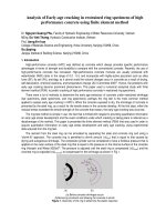
Fig. 4.9 Configuration of cracks during the steady state propagation of
interfacial crack. Solid-line shows the elliptical-shape delamination.
Normal T
n
and shear traction T
s
are acting on the crack front, while
there is no contact or no traction at the corner crack surface. Dashed
line shows the displacement of the film above the interfacial crack, δ,
due to the indentation induced stress. Bulge-out at the corner crack
might happen during the indentation, causing a minor error in the
calculation.
Fig. 4.10 Formation of an edge crack on the interface of a thin film/substrate
structure and the conventions for interfacial fracture mechanics
analysis.
Fig. 4.11 Conventions for interfacial fracture mechanics analysis.
Fig. 4.12 Phase factor, ω(α, β) in Eq. 4.8.
Fig. 4.13 Plane view of the interfacial crack pattern by SEM: (a) BD film with
thickness of 200 nm; (b) BD film with thickness of 500 nm. Interfacial
crack front is taken as before the crack kinks into the film and toward
film surface.
Fig. 4.14 FESEM plane-view image of delaminated area on 500nm BD film. A
ninth-order polynomial function is fitted to the crack front in order to
determine the curvature of the crack front.
Fig. 4.15 Curvature of interfacial crack front determined for the BD films with
thickness ranging from 100 to 1000nm.
xv
Fig. 4.16 FESEM plane-view images of the wedge indentation sites and the
associated interfacial crack front on (a) the 100 nm BD film: a straight
crack front; (b) the 300 nm BD film: a slightly curved crack front; (c)
the 500 nm BD film: a curved crack front, and (d) the 1000 nm BD
film: almost circular delamination.
Fig. 4.17 Comparison between the indentation-induced stress and the critical
buckling stress to verify the delamination mode. Open boxes represent
the indentation-induced stress calculated based on Eq.(4.1). Closed
boxes represent the critical buckling stress calculated using the
literature value of Y = 1.000 for 100 nm BD film, and 1.488 for 500
and 1000 nm BD films. For intermediate film thickness, 300 nm BD
film, the open triangle represents the critical buckling stress calculated
using the approximated value of Y = 1.390, while closed triangles
represent that calculated by using the upper and lower bounds of Y
(1.000 and 1.488).
Fig. 4.18 E
f
(unfilled boxes) and S
2
/P (filled boxes) obtained from
nanoindentation with the CSM option on the MSQ film at the 200 nm
penetration depth.
Fig. 4.19 Cross-sectional views (MSQ film) by FIB to examine 2b’: (a) 90°
wedge tip indentation, (b) 120° wedge tip indentation, and (c) cross-
sectional view at 500 nm away from the end of the wedge indent for
the 90° wedge tip indentation.
Fig. 4.20 Plane view of the interfacial crack pattern by SEM: (a) BD film with
thickness of 200 nm; (b) BD film with thickness of 500 nm.
Fig. 4.21 Interfacial toughness for the BD films with thickness ranging from
100 nm to 1000 nm. The interfacial toughness for the MSQ film
measured in Section 4.4.2 is also included for comparison.
Fig. 4.22 Computed hardness, F/(a*l) versus wedge indenter length normalized
by a half width of the indentation l/a.
Fig. 4.23 The curvature of interfacial crack front, κ versus the ratio of wedge
indenter length and indentation half-width, l/a.
xvi
Fig. 4.24 The analysis of the P-h curve for a 500nm thick BD film to determine
the energy released during fracture. (a) Film cracking and (b)
delamination are observed at the pop-in, i.e. sudden increase of the
penetration depth (red arrows). The film crack and interfacial crack
formations processes are overlapped in the region between the two
arrows.
Fig. 4.25 The analysis of the P-h curve for a 400nm thick MSQ film to
determine the energy released during fracture. Film cracks are
observed at the pop-in, i.e. sudden increase of the penetration depth,
while interfacial cracks are observed at higher indentation loads (3mN
to 9mN).
Fig. 5.1 P-h curves obtained from load controlled actual wedge indentation
experiments and a displacement controlled FEM simulation for the
BD/Si system. Open boxes represent the 90° wedge indentation
experiment, closed boxes represent the 120° wedge indentation, and
open circles represent the simulation of 90° wedge indentation.
Fig. 5.2 P-h curves before interfacial delamination occurred for: (a) the BD/Si
system and (b) the MSQ/Si system. While open and closed triangles
represent the simulation and experiment curves of 120° wedge
indentation, respectively, open and closed square boxes represent the
simulation and experiment curves of 90° wedge indentation,
respectively.
Fig. 5.3 The BD/Si system’s interfacial energy-strength contour for 90° and
120° wedge indentation showing the intersections of P
c
90
/(σ
yf
Δ
o
) =
5.16 – 5.18µm and P
c
120
/(σ
yf
Δ
o
) = 6.58 – 6.92µm. Full lines represent
the contour for P
c
90
/(σ
yf
Δ
o
), while dashed lines represent that for
P
c
120
/(σ
yf
Δ
o
).
Fig. 5.4 The MSQ/Si system’s interfacial energy-strength contour for 90° and
120° wedge indentation showing the intersection of P
c
90
/(σ
yf
Δ
o
) = 4.52
– 6.78µm and P
c
120
/(σ
yf
Δ
o
) = 7.24 – 11.31µm. Full lines represent the
contour for P
c
90
/(σ
yf
Δ
o
), while dashed lines represent that for P
c
120
/(σ
yf
Δ
o
).
Fig. 6.1 The load-holding test results for the BD/Si system at ambient
environment: (a) load-penetration depth (P-h) curves for different
maximum loads at holding, P
max
; (b) penetration depth-holding time
(h-t) curves for different P
max
, showing the consistent S-shaped
curves, consisting of three stages.
xvii
Fig. 6.2 The load-holding test results for the MSQ/Si system at ambient
environment, showing the penetration depth - holding time (h-t)
curves for different maximum loads, P
max
that assemble simple creep-
like curves.
Fig. 6.3 The load-holding test results for the BD/Si systems with two different
film thickness (300 nm and 500 nm BD films) at ambient environment
with indentation load of 5mN. The penetration depth is normalized by
film thickness.
Fig. 6.4 The varying-loading-rates test results for the MSQ/Si system at
ambient environment, showing the load-penetration (P-h) curves for
different loading rates, dP/dt.
Fig. 6.5 The varying-loading-rates test results for the BD/Si system: (a) load-
penetration (P-h) curves for different loading rates, dP/dt, and (b) the
plot of fracture-onset load, P
onset
against loading rate, dP/dt.
Fig. 6.6 The relationship between the time-to-failure, t
f
and the maximum
load, P
max
for the BD/Si system at ambient, inert and watered
environments.
Fig. 6.7 The invert time-to-failure, 1/t
f
vs the fracture-onset-load, P
onset
.
Fig. 6.8
At stage 2C of the penetration depth–holding time (h–t) curve, film
crack connects with interfacial crack in a certain angle, α.
Fig. 7.1 Cross-sectional images of 90° wedge indentations on the RuO
2
film
(thickness, t = 150 nm). (a) Interfacial crack is found at the pop-in
load. (b) As the indentation load increases, minor film cracks can be
found at the end of the wedge indentation impression.
Fig. 7.2 (a) Cross-sectional image of 120° wedge indentation on the RuO
2
film
(thickness, t = 150 nm), showing the formation of interfacial crack at
the pop-in load. (b) Plane-view image of 120° wedge indentation on
the RuO
2
film, showing no observable film crack.
Fig. 7.3 Load versus penetration depth (P-h) curves for the RuO
2
/Si system:
(a) the 90° wedge indentation, (b) the 120° wedge indentation, and (c)
the conical indentation
xviii
Fig. 7.4 Cross-sectional image of the conical indentation (P
max
= 6mN) on the
RuO
2
/Si system, showing the circular-shaped delamination and the
crack radius, a’
Fig. 7.5 Cross-sectional image of the 90° wedge indentation on the RuO
2
film
at P
max
= 40mN, showing the interfacial and substrate cracks as the
indenter penetrates deeply into the substrate
Fig. 8.1 FIB cross-sectional image of the wedge indentation on the SiN/BD/Si
system (SiN film at the top).
Fig. 8.2 FIB cross-sectional image of the wedge indentation on the
TaN/SiN/BD/Si system (TaN film at the top).
Fig. 8.3 FIB cross-sectional image of the wedge indentation on the
Cu/TaN/SiN/BD/Si system (Cu film at the top).
xix
List of Symbols
a
The half width of an indentation contact
A
Crack area
a'
The crack radius of a circular shaped delamination, the short
axis crack length of an elliptical shaped delamination or the
crack length of a rectangular shaped delamination
b'
The long axis crack length of an elliptical shaped
delamination or the width of the fine-line for microwedge
indentation method
E
Elastic modulus
G
Strain energy release rate
G
TH
The threshold strain energy release rate, below which there is
zero crack growth
h
Penetration depth
h
p
Indentation plastic depth
H
Hardness
k
Dielectric constant
l
The length of wedge indenter tip
N
The strain hardening exponential
P
Indentation load
xx
P
c
Critical indentation load for interfacial crack initiation
P
90
c
Critical indentation load for interfacial crack initiation for 90°
wedge indentation
P
120
c
Critical indentation load for interfacial crack initiation for
120° wedge indentation
P
pop-in
Indentation load for pop-in or sudden increase of penetration
depth
P
max
Maximum indentation load
P
onset
The onset load for time-dependent fracture
S
Contact stiffness
S
1
The slopes of the curves at stage 1 of the penetration depth-
holding time (h-t) curves
S
2A
, S
2B
and S
2C
The slopes of the curves at stage 2 of the penetration depth-
holding time (h-t) curves
t
Film thickness
t
f
Time-to-failure
t
1
Time duration of stage 1 of the penetration depth-holding
time (h-t) curves
t
2A
, t
2B
and t
2C
Time durations of stage 2 of the penetration depth-holding
time (h-t) curves
U
fr
Energy dissipated due to fracture
V
o
Indentation volume
xxi
V
c
Interfacial crack volume
W
i
Work of indentation
Y
The dimensionless constant introduced in Eq.(4.10) to
determine the critical buckling stress
da/dt or v The subcritical crack growth rate
dh/dt Indentation penetration rate
dP/dt
Indentation loading rate
2
φ
The inclination angle of a wedge indenter tip
β
The inclination angle between the film surface and the wedge
surface (90° minus
φ
)
κ
Crack front curvature
σ
o
Indentation induced stress
σ
c
Critical buckling stress
σ
strength
Interfacial strength
σ
y
Yielding strength
ν Poisson’s ratio
Γ
Interface toughness
ψ
The phase angle for the mode mixity between mode I and II
fracture
1
Chapter 1: Introduction
Many technologically advanced devices, such as microelectronics,
optoelectronics, biomedical and data storage devices, are constructed by depositing
layers of nanometer thin film structures on a substrate. In this thin film/substrate
structure, it is common to see materials from all three basic classes – metals, ceramics
and polymers. Because of the differences in chemical composition and atomic
structure, materials from each class have distinct characteristics and are used in a thin
film/substrate structure for different purposes. With regard to mechanical
characteristics, ceramics are typically brittle and susceptible to fracture. Ceramic thin
films and their interfaces are usually the weakest part in a thin film/substrate structure.
To ensure reliable device operations, it is important that the films and substrate
materials not only fulfill their functional purposes, but also have desirable mechanical
properties, e.g. elastic modulus, hardness, interfacial toughness and time-dependent
fracture properties. Many mechanical measurement techniques have been developed
for the purposes of quality control and materials development. In this chapter, an
overview of these topics will be briefly discussed. Section 1.1 presents an overview of
the experimental methods for thin film/substrate interfacial toughness characterization.
Section 1.2 presents a group of thin film materials (low dielectric constant (k) thin
films) that has very weak interfacial toughness due to their inherent porous structure.
Chapter 1
2
1.1 Overview of the Interfacial Toughness Characterization Methods
Fig. 1.1: Mechanical flexure tests on thin film/substrate samples: (a) Four-point-
bending and (b) double-cantilever-cleavage. Interface of interest is sandwiched
between two stiff substrates.
Over the last few decades, several experimental methods have been developed
to characterize the interfacial toughness of thin film/substrate structures, including
mechanical flexure tests [1-3] and indentation tests [4-16]. The mechanical flexure or
bending tests, such as four-point-bending and double-cantilever-cleavage, have been
shown to provide accurate quantitative results of interfacial toughness. Fig. 1.1 shows
the schematics of the four-point-bending and the double-cantilever-cleavage tests. An
important feature of the flexure tests is to sandwich the thin films between two stiff
substrates by diffusion-bonding or epoxy-glued. The sandwiched stack of films and
substrates are then cut into well defined fracture mechanics sample geometry. During
film decohesion, the stiff substrates prevent the film residual stress from being relaxed
and contributed to the crack driving force. The only limitation of the flexure tests is
the complicated and time-consuming experimental methodology, such as the
preparations of stacked samples and the bending of the stacked samples one-by-one
without process automation.