Optimal power allocation for fading channels in cognitive radio networks
Bạn đang xem bản rút gọn của tài liệu. Xem và tải ngay bản đầy đủ của tài liệu tại đây (1.03 MB, 191 trang )
OPTIMAL POWER ALLOCATION FOR FADING CHANNELS
IN COGNITIVE RADIO NETWORKS
KANG XIN
NATIONAL UNIVERSITY OF SINGAPORE
2010
OPTIMAL POWER ALLOCATION FOR FADING CHANNELS
IN COGNITIVE RADIO NETWORKS
KANG XIN
(B. Eng., Xi’an Jiaotong University, China)
A THESIS SUBMITTED
FOR THE DEGREE OF DOCTOR OF PHILOSOPHY
DEPARTMENT OF ELECTRICAL AND COMPUTER ENGINEERING
NATIONAL UNIVERSITY OF SINGAPORE
2010
Acknowledgement
First of all, I would like to express my sincere gratitude and appreciation to my advisors
Prof. Hari Krishna Garg and Dr. Ying-Chang Liang for their valuable guidance and
helpful technical support throughout my Ph.D course. Had it not been for their advices,
direction, patience and encouragement, this thesis would certainly not be possible.
I would like to thank Dr. Rui Zhang in Institute for Infocomm Research, and Dr.
Arumugam Nallanathan in King’s College London, with whom I have had the good
fortune to collaborate.
My thanks also go to my research groupmates Edward Chu Yeow Peh, Yiyang Pei,
Shoukang Zheng, Ebrahim Avazkonandeh Gharavol, and Yonghong Zeng in Institute
for Infocomm Research for their kind discussion and good advices on my research
topics. Meanwhile, I would like to thank my colleagues Feifei Gao, Jinhua Jiang, Wei
Cao, Qian Chen, Mingwei Wu, PeiJie Wang, Le Cao, Yang Lu, Jianwen Zhang, Hon-
Fah Chong, and Pham The Hanh in the ECE-I
2
R Wireless Communications Laboratory
at the Department of Electrical and Computer Engineering for their friendship and
help.
Lastly, and most importantly, I would like to thank my parents and my wife for
their love, support, and encouragement.
ii
Contents
Acknowledgement ii
Contents iii
Summary ix
List of Figures xi
List of Tables xiv
List of Notations xv
List of Abbreviations xvi
1 Introduction 1
1.1 Motivations . . . . . . . . . . . . . . . . . . . . . . . . . . . . . . . 1
1.2 Cognitive Radio Models . . . . . . . . . . . . . . . . . . . . . . . . 2
1.2.1 The opportunistic spectrum access model . . . . . . . . . . . 3
1.2.2 The spectrum sharing model . . . . . . . . . . . . . . . . . . 5
1.3 Related Work and Challenges . . . . . . . . . . . . . . . . . . . . . . 7
1.4 Contributions and Organization of the Thesis . . . . . . . . . . . . . 10
2 Optimal Power Allocation for Single-SU Fading CR Channels: Ergodic,
iii
CONTENTS
Delay-limited, and Outage Capacities 13
2.1 Introduction . . . . . . . . . . . . . . . . . . . . . . . . . . . . . . . 14
2.2 System Model and Power Constraints . . . . . . . . . . . . . . . . . 16
2.2.1 System model . . . . . . . . . . . . . . . . . . . . . . . . . . 16
2.2.2 Power constraints . . . . . . . . . . . . . . . . . . . . . . . . 17
2.3 Ergodic Capacity . . . . . . . . . . . . . . . . . . . . . . . . . . . . 18
2.3.1 Peak transmit and peak interference power constraint . . . . . 18
2.3.2 Peak transmit and average interference power constraint . . . 19
2.3.3 Average transmit and peak interference power constraint . . . 20
2.3.4 Average transmit and average interference power constraint . 20
2.4 Delay-limited Capacity . . . . . . . . . . . . . . . . . . . . . . . . . 21
2.4.1 Rayleigh fading . . . . . . . . . . . . . . . . . . . . . . . . . 22
2.4.2 Nakagami fading . . . . . . . . . . . . . . . . . . . . . . . . 22
2.4.3 Log-normal shadowing . . . . . . . . . . . . . . . . . . . . . 23
2.5 Outage Capacity . . . . . . . . . . . . . . . . . . . . . . . . . . . . . 24
2.5.1 Peak transmit and peak interference power constraint . . . . . 24
2.5.2 Peak transmit and average interference power constraint . . . 25
2.5.3 Average transmit and peak interference power constraint . . . 25
2.5.4 Average transmit and average interference power constraint . 26
2.5.5 Analytical Results . . . . . . . . . . . . . . . . . . . . . . . 27
2.6 Simulation Results . . . . . . . . . . . . . . . . . . . . . . . . . . . 30
2.6.1 Ergodic capacity . . . . . . . . . . . . . . . . . . . . . . . . 30
2.6.2 Delay-limited capacity and outage capacity . . . . . . . . . . 33
2.7 Conclusions . . . . . . . . . . . . . . . . . . . . . . . . . . . . . . . 37
3 Optimal Power Allocation for Fading Cognitive Multiple Access Channels:
Outage Capacity Regions 38
iv
CONTENTS
3.1 Introduction . . . . . . . . . . . . . . . . . . . . . . . . . . . . . . . 39
3.2 System Model . . . . . . . . . . . . . . . . . . . . . . . . . . . . . . 41
3.2.1 System Model . . . . . . . . . . . . . . . . . . . . . . . . . 41
3.2.2 Power Constraints . . . . . . . . . . . . . . . . . . . . . . . 42
3.3 Common Outage Capacity For Fading C-MAC . . . . . . . . . . . . 43
3.3.1 Definition of Common Outage Capacity . . . . . . . . . . . . 43
3.3.2 Common Usage Probability Maximization . . . . . . . . . . 44
3.4 Individual Outage Capacity For Fading C-MAC . . . . . . . . . . . . 50
3.4.1 Definition of Individual Outage Capacity . . . . . . . . . . . 50
3.4.2 Individual Usage Probability Region . . . . . . . . . . . . . . 51
3.4.3 M SUs scenario . . . . . . . . . . . . . . . . . . . . . . . . 55
3.5 Numerical Results . . . . . . . . . . . . . . . . . . . . . . . . . . . . 57
3.5.1 Common Outage Capacity . . . . . . . . . . . . . . . . . . . 57
3.5.2 Individual Outage Capacity . . . . . . . . . . . . . . . . . . 59
3.6 Conclusions . . . . . . . . . . . . . . . . . . . . . . . . . . . . . . . 61
4 Optimal Power Allocation for Fading CR Networks with PU Outage Con-
straint 63
4.1 Introduction . . . . . . . . . . . . . . . . . . . . . . . . . . . . . . . 64
4.2 System Model . . . . . . . . . . . . . . . . . . . . . . . . . . . . . . 66
4.2.1 Channel Model . . . . . . . . . . . . . . . . . . . . . . . . . 66
4.2.2 Primary User Transmission . . . . . . . . . . . . . . . . . . . 67
4.2.3 Secondary User Transmission . . . . . . . . . . . . . . . . . 68
4.3 Ergodic Capacity of SU under PU Outage Constraint . . . . . . . . . 69
4.3.1 Average Power Constraint . . . . . . . . . . . . . . . . . . . 70
4.3.2 Peak Power Constraint . . . . . . . . . . . . . . . . . . . . . 74
4.4 Outage Capacity of SU under PU Outage Constraint . . . . . . . . . . 76
v
CONTENTS
4.4.1 Average Power Constraint . . . . . . . . . . . . . . . . . . . 77
4.4.2 Peak Power Constraint . . . . . . . . . . . . . . . . . . . . . 81
4.5 Simulation Results . . . . . . . . . . . . . . . . . . . . . . . . . . . 83
4.5.1 Ergodic Capacity of SU . . . . . . . . . . . . . . . . . . . . 84
4.5.2 Outage Capacity of SU . . . . . . . . . . . . . . . . . . . . . 85
4.5.3 Imperfect Channel Estimation . . . . . . . . . . . . . . . . . 87
4.6 Concluding Remarks . . . . . . . . . . . . . . . . . . . . . . . . . . 90
5 Optimal Power Allocation for OFDM-based fading CR Networks with PU
Rate Loss Constraint 91
5.1 Introduction . . . . . . . . . . . . . . . . . . . . . . . . . . . . . . . 92
5.2 System Model . . . . . . . . . . . . . . . . . . . . . . . . . . . . . . 94
5.3 Achievable Rate of SU under the Rate Loss Constraint . . . . . . . . 97
5.4 Relationship between the Rate Loss Constraint and the Interference
Power Constraint . . . . . . . . . . . . . . . . . . . . . . . . . . . . 103
5.4.1 The per user based interference power constraint . . . . . . . 104
5.4.2 The per subcarrier based interference power constraint . . . . 105
5.5 Achievable Rate of SU with Hybrid Protection to PUs . . . . . . . . . 106
5.6 Numerical Results . . . . . . . . . . . . . . . . . . . . . . . . . . . . 111
5.6.1 Example 1: Effects of rate loss constraints on SU’s transmis-
sion rate . . . . . . . . . . . . . . . . . . . . . . . . . . . . . 111
5.6.2 Example 2: Comparison of the rate loss constraint and per sub-
carrier based interference power constraint . . . . . . . . . . 112
5.6.3 Example 3: Effects of imperfect CSI on PU’s rate loss . . . . 113
5.6.4 Example 4: Comparison of the hybrid protection constraint
and per user based interference power constraint . . . . . . . 116
5.7 Conclusions . . . . . . . . . . . . . . . . . . . . . . . . . . . . . . . 117
vi
CONTENTS
6 Sensing-based Spectrum Sharing in Fading CR Networks 118
6.1 Introduction . . . . . . . . . . . . . . . . . . . . . . . . . . . . . . . 119
6.2 System Model . . . . . . . . . . . . . . . . . . . . . . . . . . . . . . 120
6.2.1 System Model . . . . . . . . . . . . . . . . . . . . . . . . . 120
6.2.2 Spectrum Sensing Model . . . . . . . . . . . . . . . . . . . . 120
6.2.3 Transmission Model . . . . . . . . . . . . . . . . . . . . . . 121
6.3 Problem Formulation . . . . . . . . . . . . . . . . . . . . . . . . . . 122
6.4 Sensing-based Spectrum Sharing under Perfect Sensing . . . . . . . . 124
6.5 Sensing-based Spectrum Sharing under imperfect Sensing . . . . . . 127
6.6 Numerical Results . . . . . . . . . . . . . . . . . . . . . . . . . . . . 129
6.6.1 Perfect Sensing Scenario . . . . . . . . . . . . . . . . . . . . 129
6.6.2 Imperfect Sensing Scenario . . . . . . . . . . . . . . . . . . 131
6.7 Conclusions . . . . . . . . . . . . . . . . . . . . . . . . . . . . . . . 133
7 Conclusions and Future Work 134
7.1 Conclusions . . . . . . . . . . . . . . . . . . . . . . . . . . . . . . . 134
7.2 Future Work . . . . . . . . . . . . . . . . . . . . . . . . . . . . . . . 136
7.2.1 Distributed Resource Allocation in Fading CR Networks . . . 137
7.2.2 Resource Allocation for Fading CR networks with Imperfect CSI137
7.2.3 Resource Allocation for MIMO CR networks . . . . . . . . . 137
7.2.4 Upper Layer Issues for Fading CR Networks . . . . . . . . . 138
7.2.5 Resource Allocation for Femtocell Networks . . . . . . . . . 138
A Appendices to Chapter 2 139
A.1 Proof of Theorem 2.1 . . . . . . . . . . . . . . . . . . . . . . . . . . 139
A.2 Proof of Theorem 2.3 . . . . . . . . . . . . . . . . . . . . . . . . . . 142
vii
CONTENTS
B Appendices to Chapter 3 144
B.1 Proof of Proposition 3.2 . . . . . . . . . . . . . . . . . . . . . . . . . 144
C Appendices to Chapter 5 147
C.1 Proof of Theorem 5.1 . . . . . . . . . . . . . . . . . . . . . . . . . . 147
C.2 Proof of Proposition 5.1 . . . . . . . . . . . . . . . . . . . . . . . . . 148
D Appendices to Chapter 6 149
D.1 Proof of Proposition 6.1 . . . . . . . . . . . . . . . . . . . . . . . . . 149
Bibliography 151
List of Publications 171
viii
Summary
With the rapid development of wireless services and applications, the currently de-
ployed radio spectrum is becoming more and more crowded. How to accommodate
more wireless services and applications within the limited radio spectrum becomes a
big challenge faced by modern society. Cognitive radio (CR) is proposed as a promis-
ing technology to tackle this challenge by introducing the secondary (unlicensed) users
to opportunistically or concurrently access the spectrum allocated to primary (licensed)
users. Currently, there are two prevalent CR models: the opportunistic spectrum access
model and the spectrum sharing model. In the opportunistic spectrum access model,
secondary users (SUs) are allowed to access the spectrum only if the primary users
(PUs) are detected to be inactive. In the spectrum sharing model, the SUs are allowed
to coexist with the PUs as long as the interference from SUs do not degrade the quality
of service (QoS) of PUs to an unacceptable level.
This thesis studies a number of topics in CR networks under the framework of the
spectrum sharing model. First, we investigate the ergodic, delay-limited, and outage
capacity of a single SU point-to-point channel under various fading models. The opti-
mal power allocation strategies to achieve these capacities are derived under different
combinations of peak and average transmit/interference power constraints. Then, we
extend the obtained results to the multi-SU scenario. Specifically, the outage capacity
regions for a M-SU cognitive multiple access channel (C-MAC) network is character-
ized. The optimal resource allocation schemes to achieve the boundary points of the
ix
CONTENTS
defined outage capacity regions are obtained. It is rigorously proved that the optimal
decoding strategy is the successive decoding strategy.
Though applying the interference power constraint to protect the PU is simple and
effective, the resultant capacities of the secondary networks is not high. With the aim
to improve the capacities of fading CR networks, new PU protection techniques are
studied in this thesis. Start from the single-user single-carrier scenario, we propose
the PU outage constraint. This new type of constraint protects the PU by limiting the
maximum transmission outage probability of the PU to be below a desired target. The
optimal power allocation strategies for the SU to maximize its ergodic/outage capacity
are derived under the proposed PU outage constraint. It is shown that the obtained
power allocation strategies can achieve substantial capacity gains for the SU over the
conventional schemes obtained under the interference power constraint, with the same
resultant PU outage probability. Then, we consider a more challenging scenario: the
multi-carrier scenario. The rate loss constraint, in the form of an upper bound on the
maximum rate loss of each PU due to the CR transmission, is proposed to protect PUs
for an OFDM-based spectrum sharing network. It is shown that the cognitive system
can achieve a significant rate gain under the proposed rate loss constraint as compared
to that under the interference power constraint.
Finally, a new spectrum sharing model, called sensing-based spectrum sharing
is proposed for fading CR networks. In this model, SU first listens to the spectrum
allocated to the PU to detect the state of PU, and then adapts its transit power based
on the sensing results. If the PU is inactive, SU allocates the transmit power based
on its own benefit. However, if the PU is active, the interference power constraint is
imposed to protect the PU. Under this new model, the optimal sensing time and power
allocation strategies to achieve the ergodic capacity are studied. It is shown that SU
can achieve a significant capacity gain under the proposed model over that under either
the opportunistic spectrum access or the conventional spectrum sharing model.
x
List of Figures
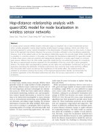
1.1 The opportunistic spectrum access model. The shadowed area denotes
the spectrum occupied by the PU. The white area with dash line de-
notes spectrum holes which could be utilized by the SU. . . . . . . . 4
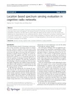
1.2 The spectrum sharing model. SU-Tx, SU-Rx, PU-Tx and PU-Rx de-
note the SU transmitter, the SU receiver, the PU transmitter and the PU
receiver, respectively. . . . . . . . . . . . . . . . . . . . . . . . . . . 6
2.1 System model for spectrum sharing in cognitive radio networks. . . . 16
2.2 Ergodic capacity vs. P
pk
with Q
pk
= −5dB for different channel models. 31
2.3 Ergodic capacity under peak transmit and average interference power
constraints. . . . . . . . . . . . . . . . . . . . . . . . . . . . . . . . 32
2.4 Ergodic capacity vs. P
av
under peak or average interference power
constraints. . . . . . . . . . . . . . . . . . . . . . . . . . . . . . . . 32
2.5 Delay-limited capacity vs. Q
av
with P
av
= 10dB for different fading
channel models. . . . . . . . . . . . . . . . . . . . . . . . . . . . . 33
2.6 Outage probability vs. Q
pk
for r
0
= 1 bit/complex dim. P
pk
= 10dB
for different fading channel models. . . . . . . . . . . . . . . . . . . 34
2.7 Outage probability for r
0
= 1 bit/complex dim. under peak or average
interference power constraints . . . . . . . . . . . . . . . . . . . . . 35
xi
LIST OF FIGURES
2.8 Outage probability for r
0
= 1 bit/complex dim. under peak interfer-
ence power constraint only. . . . . . . . . . . . . . . . . . . . . . . . 36
2.9 Outage probability for r
0
= 1 bit/complex dim. under average inter-
ference power constraint only. . . . . . . . . . . . . . . . . . . . . .
37
3.1 System model for fading C-MAC . . . . . . . . . . . . . . . . . . . . 41
3.2 Minimum common outage probabilities for two SUs under difference
interference power constraint with target rate vector R = [1 1]
T
bit/complex
dim. vs. P . . . . . . . . . . . . . . . . . . . . . . . . . . . . . . . . 58
3.3 Minimum common outage probabilities for different M with Q =
10dB vs. P . . . . . . . . . . . . . . . . . . . . . . . . . . . . . . . 59
3.4 Comparison of individual usage probabilities of two-SU case under
difference interference power constraints with target rate vector R =
[1 1]
T
bit/complex dim. vs. P . . . . . . . . . . . . . . . . . . . . . . 60
3.5 Minimum individual outage probabilities comparison between the op-
timal and sub-optimal decoding strategy for two-SU case under Q =
10dB with target rate vector R = [1 1]
T
bit/complex dim. vs. P . . . 61
4.1 Channel model. . . . . . . . . . . . . . . . . . . . . . . . . . . . . . 65
4.2 Illustration of different forms of function f(p
s
) − µχ
p
(p
s
). . . . . . . 72
4.3 Illustration of different forms of function q(p
s
). . . . . . . . . . . . . 78
4.4 Illustration of different forms of function q(p
s
) + µχ
p
(p
s
). . . . . . . 79
4.5 Comparison of the SU ergodic capacities under the PU outage con-
straint versus the IT constraint. . . . . . . . . . . . . . . . . . . . . . 84
4.6 Comparison of the SU ergodic capacities for average versus peak trans-
mit power constraint. . . . . . . . . . . . . . . . . . . . . . . . . . . 85
4.7 Comparison of the SU outage probabilities with constant rate r
s
= 1
bit/complex dim. under the PU outage constraint versus the IT constraint. 86
xii
LIST OF FIGURES
4.8 Comparison of the SU outage capacities for average versus peak trans-
mit power constraint. . . . . . . . . . . . . . . . . . . . . . . . . . . 87
4.9 Effects of imperfect channel estimation on the PU outage probability
degradation. . . . . . . . . . . . . . . . . . . . . . . . . . . . . . . .
88
5.1 Spectrum allocation in OFDMA-based primary system. . . . . . . . . 94
5.2 Channel model at subcarrier i, i ∈ {1, ··· , N}. . . . . . . . . . . . . 96
5.3 Transmission rate of SU vs. the transmit power constraint under dif-
ferent PU’s rate loss constraints. . . . . . . . . . . . . . . . . . . . . 112
5.4 Comparison of the SU’s transmission rate under the rate loss constraint
vs. per subcarrier based interference power constraint. . . . . . . . . . 113
5.5 Effects of imperfect channel estimation on the PU rate loss. . . . . . . 114
5.6 Comparison of the SU’s transmission rate under the hybrid protection
constraint vs. per user based interference power constraint. . . . . . . 116
6.1 Frame structure for sensing-based spectrum sharing (τ: sensing slot
duration; T −τ: data transmission slot duration) . . . . . . . . . . . 121
6.2 Capacities vs. Q
av
for different P
av
under P(H
0
) = 0.6 for perfect
sensing scenario . . . . . . . . . . . . . . . . . . . . . . . . . . . . . 130
6.3 Capacities vs. Q
av
for different P(H
0
) under P
av
= 15dB for perfect
sensing scenario . . . . . . . . . . . . . . . . . . . . . . . . . . . . 131
6.4 Capacities vs. τ for different Q
av
under P(H
0
) = 0.6 for imperfect
sensing . . . . . . . . . . . . . . . . . . . . . . . . . . . . . . . . . 132
6.5 Capacities vs. τ for different P
av
under P(H
0
) = 0.6 for imperfect
sensing . . . . . . . . . . . . . . . . . . . . . . . . . . . . . . . . . 132
xiii
List of Tables
3.1 The Modified Ellipsoid Method . . . . . . . . . . . . . . . . . . . . . 49
6.1 Four possible scenarios for sensing-based spectrum sharing . . . . . . 123
6.2 Modified subgradient algorithm for sensing-based spectrum sharing . 127
xiv
List of Notations
a lowercase letters are used to denote scalars
a boldface lowercase letters are used to denote column vectors
A boldface uppercase letters are used to denote matrices
(·)
T
the transpose of a vector or a matrix
E[·] the statistical expectation operator
max(x, y) the maximum element of x and y
min(x, y) the minimum element of x and y
(·)
+
max(0, ·)
defined as
x y element wise inequality, i.e., x
i
≤ y
i
, ∀i
xv
List of Abbreviations
AWGN Additive White Gaussian Noise
BC Broadcast Channel
BF Block Fading
BS Base Station
C-BC Cognitive Broadcast Channel
C-MAC Cognitive Multiple Access Channel
CR Cognitive Radio
CSCG Circularly Symmetric Complex Gaussian
CSI Channel State Information
FCC Federal Communications Commission
IT Interference Temperature
IWF Iterative Water Filling
KKT Karush-Kuhn-Tucker
LOS Line-Of-Sight
MAC Multiple Access Channel
MIMO Multiple Input Multiple Output
MISO Multiple Input Single Output
OFDM Orthogonal Frequency Division Multiplexing
OFDMA Orthogonal Frequency Division Multiple Access
xvi
Abbreviations
PDF Probability Density Function
PU Primary User
PU-Tx Primary User Transmitter
PU-Rx Primary User Receiver
QoS Quality-of-Service
SIMO Single Input Multiple Output
SINR Signal-to-Interference-plus-Noise Ratio
SNR Signal-to-Noise Ratio
SOCP Second Order Cone Programming
SU Secondary User
SU-Tx Secondary User Transmitter
SU-Rx Secondary User Receiver
xvii
Chapter 1
Introduction
1.1 Motivations
The demand for frequency resources has dramatically increased due to the explosive
growth of wireless applications and services in recent years. This poses a big chal-
lenge to the current fixed spectrum allocation policy. On the other hand, a report pub-
lished by Federal Communications Commission (FCC) shows that the current scarcity
of spectrum resource is mainly due to the inflexible spectrum regulation policy rather
than the physical shortage of spectrum [1]. Most of the allocated frequency bands are
under-utilized, and the utilization of the spectrum varies in time and space. Similar
observations have also been made in other countries. In particular, the spectrum uti-
lization efficiency is shown to be as low as 5% in Singapore [2]. The compelling need
to improve the spectrum utilization and establish more flexible spectrum regulations
motivates the advent of cognitive radio (CR). Compared to the traditional wireless
devices, CR devices can greatly improve the spectrum utilization by dynamically ad-
justing their transmission parameters, such as transmit power, transmission rate and the
operating frequency. Most recently, FCC agrees to open the licensed, unused televi-
sion spectrum or the so-called white spaces to the new, unlicensed, and sophisticatedly
1
1.2 Cognitive Radio Models
designed CR devices. This milestone change of policy by the FCC indicates that CR
is fast becoming one of the most promising technologies for the future radio spectrum
utilization. This also motivates a wide range of research in the CR area, including the
research work done in this thesis.
This thesis devotes to finding the optimal resources allocation strategies, and ap-
plying the resources allocation results to compute the capacities of various fading CR
networks, including single CR point-to-point channel, cognitive multiple access chan-
nels (C-MAC), and cognitive orthogonal frequency division multiplexing (OFDM) sys-
tems. This thesis also devotes to improving the capacities of fading CR networks by
improving the current CR operation models and developing new CR operation models.
In the following parts of this chapter, we briefly introduce the prevalent CR opera-
tion models, and provide overviews on related work and challenges of research topics
investigated in this these, and present the contributions and organization of this thesis.
1.2 Cognitive Radio Models
The term ”cognitive radio” was first coined by Joseph Mitola in [3], in which Mi-
tola discussed the possibility of enhancing the flexibility of personal wireless services
through CR techniques. Then, the idea of CR was further expanded and a conceptual
overview of CR was presented in [4]. In this visionary dissertation, CR is described
as a fully reconfigurable wireless device that is sufficiently intelligent about its en-
vironment (e.g., radio resources and channel fading states) and is able to automati-
cally change its operating parameters (e.g., transmit power, operating frequency, and
modulation strategy) in response to environment changes. This is regarded as the pre-
liminary prototype of the current opportunistic spectrum access model. Later, in [5],
Simon Haykin proposed the concept of interference temperature and characterized the
interference-temperature-based operation of CR. This paves the path for today’s spec-
2
1.2 Cognitive Radio Models
trum sharing model. Nowadays, CR operation models can generally be classified into
two categories: opportunistic spectrum access and spectrum sharing. In the oppor-
tunistic spectrum access model, CRs or better known as secondary users (SU) have to
sense the surrounding radio environments first, and then transmit in vacant or intermit-
tently unused spectrum without causing interference to the spectrum licensees known
as primary users (PU). In the spectrum sharing model, SU is allowed to transmit con-
currently with PU over the same frequency band provided that the PU’s performance
degradation caused by SU’s transmission is tolerable. This is realized by imposing
an interference power constraint on SU’s transmission, i.e., the interference power re-
ceived at PU’s receiver must be constrained below a certain prescribed threshold. In
the following, detail introductions of these two CR operation models are presented.
1.2.1 The opportunistic spectrum access model
As shown in Fig. 1.1, in opportunistic spectrum access model, SU first does spectrum
sensing to detect the on/off status of PU. If PU is detected to be off, i.e., the spectrum
is not currently occupied by PU, then SU can transmit over the spectrum; otherwise,
SU has to keep sensing until it finds a vacant spectrum band. These vacant spectrum
bands are also known as spectrum holes. A key feature for this model is listen-before-
talk [6], i.e. SU must first sense the spectrum bands to find the spectrum holes, and
then transmit. The process to detect the PU’s on/off status over the target spectrum is
termed as spectrum sensing [7].
Spectrum sensing plays a significant role in the opportunistic spectrum access
model, since the sensing result directly decides whether the target spectrum can be
used by the SU or not. Two key concepts associated with spectrum sharing are prob-
ability of detection and probability of false alarm. Probability of detection is defined
as the probability of correctly detecting the presence of PU when PU is active; while
3
1.2 Cognitive Radio Models
PU
PU
PU PU
Time
Frequency
PU
PU
PU
SU
SU PU
SU
Time
Frequency
Figure 1.1: The opportunistic spectrum access model. The shadowed area denotes the
spectrum occupied by the PU. The white area with dash line denotes spectrum holes
which could be utilized by the SU.
probability of false alarm is defined as the probability of falsely declaring the presence
of PU when PU ia actually inactive. How to improve the accuracy of the sensing result
is a crucial research topic in this model [8–10]. A lot of effort has been put into the
design of sensing schemes.
Basically, there are three types of spectrum sensing schemes: energy detection
[11, 12], matched filter detection [13–16], and cyclostationary feature detection [17,
18]. Energy detection is the most spectrum sensing scheme due to its low compu-
tationally complexity. However, energy detection is a suboptimal approach for any
type of signals. Matched filter detection is optimal in the background of stationary
Gaussian noise since it can achieve the maximum Signal-to-Noise Ratio (SNR). How-
ever, prior knowledge of the PU’s signal, which is not easy to obtain in practice, is
needed for coherent detection. Exploiting the feature that noise has no correlation,
while any man-made signals have some degree of correlation, cyclostationary feature
detection achieves the best performance even in the worst-case scenario of large power
level uncertainty of noise. However, the minimum number of samples required for
detection are much more than that for energy detection and match-filter detection. Re-
4
1.2 Cognitive Radio Models
cently, more advanced spectrum sensing algorithms, such as the eigenvalue based al-
gorithms [19, 20] and the covariance based algorithms [21, 22], are proposed. These
spectrum sensing algorithms make the decision based on the observations of a single
SU. When there are more than one SU in the secondary network, an more efficient
approach termed as cooperative spectrum sensing [23–37], which is able to fuse SUs’
decisions, can be used for more accurate detection of the PU’s signal. The better detec-
tion performance of cooperative sensing is achieved at the cost of additional operations
and overhead traffic, since SUs’ have to share, exchange, and fuse their detection re-
sults. Besides the above mentioned basic spectrum sensing techniques, more advanced
sensing techniques with improved sensing accuracy are reported in [38–49].
From the media access control layer’s design perspective, under this model, each
frame needs to have one sensing slot to sense the PU’s activity over the target spectrum
and one data transmission slot for SU transmission in case the spectrum is found to be
not currently occupied by PU. It is reported that the longer duration of the sensing slot
is, more accurate the sensing result is. However, longer sensing slot leads to shorter
transmission time, and thus results in a lower SU throughput. This is known as the
sensing throughput tradeoff problem, and this problem was first defined and investi-
gated in [50]. The sensing tradeoff problems for cooperative sensing and wideband
sensing scenarios were investigated in [51] and [52], respectively.
1.2.2 The spectrum sharing model
In spectrum sharing model, SU is allowed to transmit simultaneously with PU within
the same frequency band on condition that that the interferences from SU to PU will be
kept below a prescribed threshold. From this definition, it is easy to see that there are
three key features of spectrum sharing model. First, no spectrum sensing is needed at
SU. This greatly relieves the complexity of the transceiver design of SU. Secondly, SU
5
1.2 Cognitive Radio Models
SU-Tx
SU-Rx
PU-Tx
PU-Rx
Figure 1.2: The spectrum sharing model. SU-Tx, SU-Rx, PU-Tx and PU-Rx denote the
SU transmitter, the SU receiver, the PU transmitter and the PU receiver, respectively.
can start its transmission at any time without waiting for the spectrum holes. This gives
SU the potential to achieve a higher long-term capacity. Thirdly, the interference power
from SU to PU should be kept below a prescribed threshold. This can be achieved by
imposing an interference power constraint [53–55] on SU transmitter (SU-Tx). To
satisfy the interference power constraint, SU has to regulate its transmit power, and
this requires SU to have the channel state information (CSI) of the channel from the
SU-Tx to the PU receiver (PU-Rx).
From the above features of the spectrum sharing model, it is not difficult to see that
dynamic resource allocation is crucial for realizing spectrum sharing cognitive radio
networks. To be specific, with CSI available at the SU-Tx, how to dynamically ad-
just the transmit parameters, such as transmit power, bit-rate, bandwidth, and antenna
beam of SU is a significant problem need to be solved for the realization of spectrum
sharing cognitive networks. A great deal of valuable scholarly work has been done
on the design of optimal transmission strategies for CRs subject to the interference
power constraint. The centralized and decentralized resource allocation strategies for
6
1.3 Related Work and Challenges
spectrum sharing CR network are studied using optimization techniques in [56–68]
and [69–71], respectively. Besides, there are also lots of research work study the re-
source allocation problems for spectrum sharing CR network either from the game
theory perspective [72–90] or from the information theory perspective [91–100].
1.3 Related Work and Challenges
In this section, we provide a brief overview on the related work of this thesis and the
challenges for the design of resource allocation schemes for fading spectrum sharing
CR networks.
The topics of this thesis focus on the resources optimization for fading spectrum
sharing CR networks. For spectrum sharing CR networks, an important issue is to
maintain the desired quality of service (QoS) of PU yet to maximize SU’s utility func-
tion. For AWGN channels, the commonly adopted utility function is the Shannon
capacity [101], which is defined as the maximum mutual information between the
channel input and output. For fading channels, the widely used utility functions are
ergodic capacity [102] and outage capacity [103]. Ergodic capacity is defined as the
maximum mutual information averaged over all the channel fading states. It is a good
performance indicator for the delay-insensitive services when the codeword length can
be sufficiently long to span over all the fading states. For delay-sensitive applications,
a better performance measure is outage capacity, which is defined as the maximum
instantaneous information rate that can be maintained under any fading states during
non-outage for a given outage probability. The outage capacity for the extreme case
when the given outage probability is zero is also referred to as delay-limited capac-
ity. In [104], subject to the interference power constraint, the optimal power allocation
scheme was derived for SU equipped with multiple antennas to maximize the capac-
ity of a point-to-point AWGN SU channel. In [105], the ergodic capacity of a single
7