Study of field emission characteristics of ultrathin film coated carbon nanotubes core shell structures 2
Bạn đang xem bản rút gọn của tài liệu. Xem và tải ngay bản đầy đủ của tài liệu tại đây (411.52 KB, 13 trang )
Chapter 2 Physics of Field Emission
20
Chapter 2 Physics of Field Emission
In this chapter, the physics behind field emission will be reviewed in details. The
definition of field emission phenomenon and the origin of Fowler-Nordheim theory,
an evaluation approach for field emission, will be presented in section 2.1. Section 2.2
will focus on the discussion of field emission from semiconductors. The parameters
influencing the field emission properties will be covered in the last section.
2.1 Field Emission and Fowler-Nordheim Theory
Field emission is a phenomenon that describes the tunneling of an electron from
the surface of a solid into vacuum, due to the application of a strong electric field
(typically E > 10
9
V m
-1
) [1]. More specifically, it is a quantum effect when under a
sufficiently high external electric field, electrons near the Fermi level can tunnel
through the energy barrier and escape to the vacuum level [2]. It is an alternative way to
extract electrons from solid surface and it is a special case of thermionic emission.
When compared to traditional thermionic emission, this is a preferred mechanism for
certain applications such as flat panel display because no heating is required and the
emission current is almost solely controlled by the external field. The mechanism of
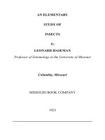
field emission is schematically illustrated in Fig. 2.1.
Fig. 2.1 Schematic p
otential
on the energy barrier for electrons at a metal surface
E
vac
represents the vacuum level,
The Fowler-
Nordheim (F
Nordheim as well as
some other researchers in order to
between the emission current density and the elect
surface [3-
6]. The derivation of F
physics such as
density of states, Fermi
thermionic emission.
approximation employed at the early stage [3, 7], the F
=
exp
)(8
2
23
yth
Fe
J
φπ
0
3
4
1
πεφ
Fe
y =
where m
e
represents the electron mass
barrier height of the emitter
Chapter 2 Physics of Field Emission
otential
energy diagram illustrating the effect of an external electric field
on the energy barrier for electrons at a metal surface
, with consideration of an image potential
represents the vacuum level,
E
F
refers to the Fermi level, and Ø
is the work function of
the metal.
Nordheim (F
-N) theory was developed by R. H
. Fowler and L. W.
some other researchers in order to
describe the relationship
between the emission current density and the elect
ric field applied on the metal
6]. The derivation of F
-N equation
is built on the basic semiconductor
density of states, Fermi
-Dirac dis
tribution, tunneling phenomenon
Considering the Wentzel-Kramers-Bril
louin (WKB)
approximation employed at the early stage [3, 7], the F
-
N equation can be written as:
− )(
3
28
exp
2/3
y
heF
m
e
υ
φπ
represents the electron mass
, h is the Planck’s constant, Ø
barrier height of the emitter
s, F is the local field, ε
0
is the permittivity of free space,
21
energy diagram illustrating the effect of an external electric field
, with consideration of an image potential
.
is the work function of
. Fowler and L. W.
describe the relationship
ric field applied on the metal
is built on the basic semiconductor
tribution, tunneling phenomenon
and
louin (WKB)
N equation can be written as:
(2.1)
(2.2)
is the emission
is the permittivity of free space,
Chapter 2 Physics of Field Emission
22
and t(y) and υ(y) are the Nordheim elliptic functions including image potential
corrections. For a triangle-shaped potential barrier used in Fowler and Nordheim’s
work, this F-N equation can be simplified by using the approximation of
1.1)(
2
≈yt
and
95.0)(
≈
y
υ
[8]. Finally, the F-N equation can be obtained:
( )
−=
E
B
E
A
J
β
φ
β
φ
α
2/3
2
exp
(2.3)
where Ø represents the emission barrier height of the emitters (eV), β refers to the field
enhancement factor, E is the applied field, α is assigned to the area where electron
emission takes place, and the universal constants A = 1.54×10
-6
A eV V
-2
and B =
6.83×10
3
eV
-3/2
V µm
-1
.
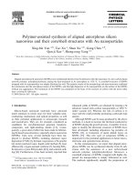
The typical FE characteristic plots are shown in Fig. 2.2. The plot of ln(J/E
2
)
versus 1/E (so called F-N plot) displayed in the inset comprised a linear region,
emphasizing the quantum tunneling electron emission mechanism. The slope of the
linear region of the F-N plot is a function of both β and Ø, which can be expressed as
below by transformation of the Eq. (2.3):
β
φ
2/3
3
1083.6 ×−=Slope
(2.4)
This equation is the most commonly used format in FE studies and it is utilized
as a standard calculation formula in order to evaluate the FE properties of different
samples all through this dissertation. The F-N equation used to be exclusively applied
on FE from bulk metals, but recently it is abundantly used in FE studies of other
materials, such as semiconductors [9-13].
Chapter 2 Physics of Field Emission
23
Fig. 2.2 The electron emission current density versus applied field (J-E) characteristics of the
specimen. The corresponding Fowler–Nordheim (F-N) plot is shown in the inset.
2.2 Field Emission from Semiconductors
Field emission was once considered to be an exclusive phenomenon of metals,
however, semiconductors were later found to exhibit similar properties and the
emission current could be approximated by the same method that Fowler and
Nordheim used as well [14]. In contrast with metals, the external electrical field
would penetrate into semiconductors and result in the band bending near the
semiconductor surface as illustrated in Fig. 2.3. This bending would lead to lowered
emission barrier height for electrons so as to enhance the FE performance of the
semiconductors.
0 1 2 3 4 5
0
2
4
6
8
0.2 0.3 0.4 0.5
-14
-12
-10
-8
-6
-4
-2
0
ln
(
J/E
2
)
1/E
Current density, J
(
mA/cm
2
)
Applied electric field, E
(
V/
µ
µµ
µ
m
)
Fig. 2.3
Energy band bending near the surface of a semiconductor induced by the external
electrical field. E
c
represents the conduction band minimum,
the valence band maximum,
The FE process for semiconductors is much more complicated as compared to
that for traditional bulk metals. For instance, it was found that for some
semiconducto
r materials, the F
slopes at low and high electrical field. This deviation might
effects, overheating of the emitter tips
conducti
on band of semiconductors
also be strongly affected by the temperature owing to their temperature
nature [10, 18, 19]. The doping type and concentration
band structures
of the semiconductors, resulting in varied emission barrier height
thus diverse FE performance
semiconductors, in some cases electrons tunnel from conduction band, some eject
from valence
band while emission from the donor level within the bandgap is also
Chapter 2 Physics of Field Emission
Energy band bending near the surface of a semiconductor induced by the external
represents the conduction band minimum,
E
F
refers to the Fermi level,
the valence band maximum,
V
0
donates the original emission barrier height, and
barrier height with band bending.
The FE process for semiconductors is much more complicated as compared to
that for traditional bulk metals. For instance, it was found that for some
r materials, the F
-
N plots comprise linear relationships with different
slopes at low and high electrical field. This deviation might
be due to
the
effects, overheating of the emitter tips
, or
the low concentration of the carriers in the
on band of semiconductors
[15-
17]. FE properties of semiconductors could
also be strongly affected by the temperature owing to their temperature
nature [10, 18, 19]. The doping type and concentration
of carriers
would influence the
of the semiconductors, resulting in varied emission barrier height
thus diverse FE performance
s
[20, 21]. Furthermore, the origin of FE is not fixed for
semiconductors, in some cases electrons tunnel from conduction band, some eject
band while emission from the donor level within the bandgap is also
24
Energy band bending near the surface of a semiconductor induced by the external
refers to the Fermi level,
E
v
is
donates the original emission barrier height, and
V is the
The FE process for semiconductors is much more complicated as compared to
that for traditional bulk metals. For instance, it was found that for some
N plots comprise linear relationships with different
the
space charge
the low concentration of the carriers in the
17]. FE properties of semiconductors could
also be strongly affected by the temperature owing to their temperature
-dependent
would influence the
of the semiconductors, resulting in varied emission barrier height
s and
[20, 21]. Furthermore, the origin of FE is not fixed for
semiconductors, in some cases electrons tunnel from conduction band, some eject
band while emission from the donor level within the bandgap is also
Chapter 2 Physics of Field Emission
25
possible [22, 23].
With the development of synthesis methods, nanosized semiconductors, such as
nanowires and nanoparticles can be produced. The dimension decrease of the
materials would induce quantum effects such as discretization of energy band, which
would confine the electron motion and change the width of the bandgap [24]. The FE
cold cathode can be fabricated with multilayer semiconductor thin film structures as
well and these films can be produced thinner than 10 nm with the sophisticated
technology [25, 26]. In this case, the substrate is usually critical important because it
acts as a primary electron source during emission process. Deposited with ultrathin
films, the FE cathode can be dramatically modified in the electronic structures hence
leading to significantly promoted FE characteristics [27]. By utilizing multilayer
ultrathin film structures as FE cold cathode, the effective emission barrier can be
controlled by monitoring the space charge value on the surface [28].
2.3 Influencing Parameters of Field Emission
Based on the above review of the F-N theory and the literature on FE from
semiconductors, it is obvious that the FE properties of materials are essentially
affected by a few parameters.
First, FE is a tunneling phenomenon of electrons from the surface of a condensed
matter to vacuum, thus excellent vacuum is a basic requirement for reliable and stable
Chapter 2 Physics of Field Emission
26
FE performance. Generally, a base pressure of below 1 × 10
-8
Torr is required for the
FE test [29]. If the operation pressure is too high, work function of the emitter may be
changed due to the gas adsorbed onto the emitter surface. Additionally, the emitted
electrons may cause ionization of the residual gas molecules, thus leading to increased
bombardment at the cathode [3, 30]. However, currently FE can also be operated at
much higher pressures where in some cases, the electron emission phenomena
occurred over a low applied voltage [31-34].
Second, the anode-cathode distance is also a parameter influencing the FE
performances of emitters. Threshold voltage, defined as the anode voltage where an
emission current of 10
-9
A was observed, is an essential index to evaluate the FE
properties of emitters [35]. The lower the threshold voltage, the lower the applied
field is needed for the commencement of FE phenomenon, thus a lower power is
required for this kind of electronic devices to work. Low power for device operation
is the ultimate goal for device manufacturing. Some researchers have investigated the
relationship between the varied anode-cathode spacing and the threshold field. Results
showed that with varied anode-cathode distances, the threshold voltage shifted
accordingly [35, 36]. With the increase of anode-cathode spacing, the threshold
voltage increased as well. With the further increase of the applied voltage, large
current density could be obtained.
Third, the surface morphology affects the emitter’s performance as well.
Generally, it is much more difficult for a smooth surface to emit electrons than for a
Chapter 2 Physics of Field Emission
27
sharp geometry in that the applied electric field tends to concentrate on the sharp point
thus resulting in a much larger local field at the emitter tips [37, 38]. The local electric
field with respect to the applied electric field is donated as the field enhancement
factor β, which can be roughly estimated by the ratio h/r, where h is the projection
height and r is the radius of the emitter tip [39]. As such, shapes like nanowires,
nanotubes and nanocones have aroused more and more interest among FE researchers
since they have sharp emission tips [40-46]. However, there is a problem with these
structures that if they are too densed, the local electric fields of the neighboring
emitters will interact such that the field gets weaken. This phenomenon is called
screening effect [47]. To avoid this effect, these emitters should possess an optimum
adjacent distance, which has been worked out to be twice the height of the emitters
[48].
In addition, the work function of the emitter also plays a crucial role in
influencing its FE properties. According to the F-N equation shown in Eq. (2.10), the
emission barrier height Ø is one of the parameters affecting the emission current J.
However, during calculation, the value of Ø is usually assumed to be similar to the
work function value. Lower work function means lower barrier height for the
quantum tunneling phenomenon. As such, reducing the work function of the emitter is
one approach to improve its FE properties. There have been considerable studies
showing that with low work function materials coated on the emitters, their threshold
voltage can be significantly reduced [49-52]. The underlying mechanism is that the
Chapter 2 Physics of Field Emission
28
coated materials have reacted and formed a Schottky contact with the emitters, thus
resulting in the modification of the band structures so as to lower the barrier height for
the quantum tunneling.
Last but not the least, one of the most important parameters that affect emitter’s
FE properties is the lifetime. The commercial use of FE devices should ensure stable
emission current for a long time. As the emitters are working in ultra-high vacuum
environment and the emitter tips always bare high electron emitting current or
elevated local temperature, corrosion or damage may happen to the emitter tips thus
affecting the lifetime of the emitters [53]. Therefore, one primary issue about FE
devices is to improve the corrosion resistance of the emitters. One of the methods, i.e.,
coating the emitters with materials of high chemical or thermal stability has been
proposed and has shown promising results [54-58].
Chapter 2 Physics of Field Emission
29
References
1. S. O. Kasap, Principles of Electronic Materials and Devices (Third edition,
McGraw-hill companies, 2006).
2. Y. Cheng and O. Zhou, C. R. Physique 4, 1021 (2003).
3. R. H. Fowler and L. Nordheim, Proc. R. Soc. Lond. A 119, 173 (1928).
4. L. W. Nordheim, Proc. R. Soc. Lond. A 121, 626 (1928).
5. R. H. Good and E. W. Mueller, Field emission (Vol. 21, Springer, 1956).
6. J. W. Gadzuk and E. W. Plummer, Rev. Mod. Phys. 45, 487 (1973).
7. H. J. Jeffreys, Proc. London Math. Soc. 23, 428 (1924).
8. Y. Saito, Carbon Nanotube and Related Field Emitters: Fundamentals and
Applications (Wiley-VCH, 2010).
9. D. Temple, Mater. Sci. Eng. R 24, 185 (1999).
10. G. Pananakakis, G. Ghibaudo, R. Kies, and C. Papadas, J. Appl. Phys. 78, 2635
(1995).
11. M. S. Chung and B. G. Yoon, J. Vac. Sci. Technol. B 21, 548 (2003).
12. R. N. Tiwari and L. Chang, J. Appl. Phys. 107, 103305 (2010).
13. X. Fang, Y. Bando, U. K. Gautam, C. Ye, and D. Golberg, J. Mater. Chem. 18,
509 (2008).
14. R. Stratton, Proc. Phys. Soc. B 68, 746 (1955).
15. P. Rai, D. R. Mohapatra, K. S. Hazra, D. S. Misra, and S. P. Tiwari, Appl. Phys.
Lett. 93, 131921 (2008).
16. C. M. Tan, J. Jia, and W. Yu, Appl. Phys. Lett. 86, 263104 (2005).
17. J. Yu, Q. Zhang, J. Ahn, S. F. Yoon, Rusli, Y. J. Li, B. Gan, K. Chew, and K. H. Tan,
Diamond Relat. Mater. 10, 2157 (2001).
18. P. S. Riseborough, Phys. Rev. B 58, 15534 (1998).
19. S. Das, S. F. Ahmed, M. K. Mitra, and K. K. Chattopadhyay, Appl. Phys. A: Mater.
Sci. Proc. 91, 429 (2008).
Chapter 2 Physics of Field Emission
30
20. C. S. Chang, S. Chattopadhyay, L. C. Chen, K. H. Chen, C. W. Chen, Y. F. Chen, R.
Collazo, and Z. Sitar, Phys. Rev. B 68, 125322 (2003).
21. L. Diederich, O. M. Küttel, P. Aebi, and L. Schlapbach, Surf. Sci. 418, 219
(1998).
22. S. R. P. Silva, J. D. Carey, X. Guo, W. M. Tsang, and C. H. P. Poa, Thin Solid
Films 482, 79 (2005).
23. H. Yamaguchi, T. Yamada, M. Kudo, Y. Takakuwa, and K. Okano, Appl. Phys. Lett.
88, 202101 (2006).
24. M. Dragoman and D. Dragoman, Nanoelectronics: Principles and Devices
(Second Edition, Artech House, Inc., 2009).
25. Z. Q. Duan, R. Z. Wang, R. Y. Yuan, W. Yang, B. Wang, and H. Yan, J. Phys. D:
Appl. Phys. 40, 5828 (2007).
26. T. Sugino, C. Kimura, and T. Yamamoto, Appl. Phys. Lett. 80, 3602 (2002).
27. W. Zhao, R. Z. Wang, S. Han, K. Xue, H. Wang, and H. Yan, J. Phys. Chem. C
114, 11584 (2010).
28. V. Semet, V. T. Binh, J. P. Zhang, J. Yang, M. A. Khan, and R. Tsu, Appl. Phys.
Lett. 84, 1937 (2004).
29. D. Temple, Mater. Sci. Eng. R 24, 185 (1999).
30. P.R. Schwoebel and I. Brodie, J. Vac. Sci. Technol. B 13, 1391 (1995).
31. D.G. Walker, C.T. Harris, T.S. Fisher, and J.L. Davidson, Diamond Relat. Mater.
14, 113 (2005).
32. J. Li, W. Zheng, C. Gu, Z. Jin, Y. Zhao, X. Mei, Z. Mu, C. Dong, and C. Sun,
Carbon 42, 2309 (2004).
33. N. Ghosh, W. P. Kang, Y. M. Wong, and J. L. Davidson, Diamond Relat. Mater.
19, 247 (2010).
34. W. C. Shih, J. M. Jeng, M. H. Tsai, and J. T. Lo, Appl. Surf. Sci. 256, 2409
(2010).
35. A. N. Banerjee and K. K. Chattopadhyay, Appl. Surf. Sci. 225, 243 (2004).
Chapter 2 Physics of Field Emission
31
36. Y. Kudo, T. Yamada, H. Yamaguchi, T. Masuzawa, I. Saito, S. Shikata, C. E.
Nebel, and K. Okano, Jpn. J. Appl. Phys. 47, 8921 (2008).
37. E. Stratakis, R. Giorgi, M. Barberoglou, T. Dikonimos, E. Salernitano, N. Lisi,
and E. Kymakis, Appl. Phys. Lett. 96, 043110 (2010).
38. S. Tsujino, P. Beaud, E. Kirk, T. Vogel, H. Sehr, J. Gobrecht, and A. Wrulich,
Appl. Phys. Lett. 92, 193501 (2008).
39. M. Jimenez, R. J. Noer, G. Jouve, J. Jodet, and B. Bonin, J. Phys. D: Appl. Phys.
27, 1038 (1994).
40. Y. Chen, Z. Sun, J. Chen, N. S. Xu, and B. K. Tay, Diamond Relat. Mater. 15,
1462 (2006).
41. G. N. Fursey, D. V. Novikov, G. A. Dyuzhev, A. V. Kotcheryzhenkov, and P. O.
Vassiliev, Appl. Surf. Sci. 215, 135 (2003).
42. C. Li, Y. Zhang, M. Mann, P. Hiralal, H. E. Unalan, W. Lei, B. P. Wang, D. P.
Chu, D. Pribat, G. A. J. Amaratunga, and W. I. Milne, Appl. Phys. Lett. 96,
143114 (2010).
43. D. Banerjee, S. H. Jo, and Z. F. Ren, Adv. Mater. 16, 2028 (2004).
44. Y. W. Zhu, A. M. Moo, T. Yu, X. J. Xu, X. Y. Gao, Y. J. Liu, C. T. Lim, Z. X.
Shen, C. K. Ong, A. T. S. Wee, J. T. L. Thong, and C. H. Sow, Chem. Phys. Lett.
419, 458 (2006).
45. F. Liu, J. Tian, L. Bao, T. Yang, C. Shen, X. Lai, Z. Xiao, W. Xie, S. Deng, J. Chen,
J. She, N. Xu, and H. Gao, Adv. Mater. 20, 2609 (2008).
46. P. R. Vinod, T. Yamada, D. S. Hwang, and N. Fujimori, Jpn. J. Appl. Phys. 44,
L497 (2005).
47. L. Nilsson, O. Groening, C. Emmenegger, O. Kuettel, E. Schaller, L. Schlapbach,
H. Kind, J-M. Bonard, and K. Kern, Appl. Phys. Lett. 76, 2071 (2000).
48. M. Dionne, S. Coulombe, and J. L. Meunier, IEEE Transactions on Electron
Devices 55, 1298 (2008).
49. J. Xu, J. Mei, X.H. Huang, X. Li, Z. Li, W. Li, and K. Chen, Appl. Phys. A: Mater.
Chapter 2 Physics of Field Emission
32
Sci. Process 80, 123 (2005).
50. L. Yuan, G. Fang, C. Li, J. Li, M. Wang, N. Liu, and X. Zhao, Surf. Coat. Technol.
202, 3480 (2008).
51. S. A. Pshenichnyuk and Y. M. Yumaguzin, Technical Phys. Lett. 26, 79 (2000).
52. H. Saitoh, H. Akasaka, T. Washio, Y. Ohkawara, S. Ohshio, and H. Ito, Jpn. J. Appl.
Phys. 41, 6169 (2002).
53. Jon Orloff, Handbook of Charged Particle Optics (CRC Press, USA, 1997) pp.
201.
54. C. M. Lin, S. J. Chang, M. Yokoyama, I. N. Lin, F. Y. Chuang, C. H. Tsai, and W.
C. Wang, Jpn. J. Appl. Phys. 38, 3700 (1999).
55. J. Zhang, C. Yang, Y. Wang, T. Feng, W. Yu, J. Jiang, X. Wang, and X. Liu,
Nanotechnology 17, 257 (2006).
56. C. J. Yang, J. I. Park, and Y. R. Cho, Adv. Eng. Mater. 9, 88 (2007).
57. H. W. Park, B. K. Ju, Y. H. Lee, J. H. Park, and M. H. Oh, Jpn. J. Appl. Phys. 35,
L1301 (1996).
58. C. Liu, K. S. Kim, J. Baek, Y. Cho, S. Han, S. W. Kim, N. K. Min, Y. Choi, J. U.
Kim, and C. J. Lee, Carbon 47, 1158 (2009).