Resource optimization for multi antenna cognitive radio networks
Bạn đang xem bản rút gọn của tài liệu. Xem và tải ngay bản đầy đủ của tài liệu tại đây (844.42 KB, 181 trang )
RESOURCE OPTIMIZATION FOR MULTI-ANTENNA
COGNITIVE RADIO NETWORKS
ZHANG LAN
NATIONAL UNIVERSITY OF SINGAPORE
2009
RESOURCE OPTIMIZATION FOR MULTI-ANTENNA
COGNITIVE RADIO NETWORKS
ZHANG LAN
(M. Eng., University of Electronic Science and Technology of China)
A THESIS SUBMITTED
FOR THE DEGREE OF DOCTOR OF PHILOSOPHY
DEPARTMENT OF ELECTRICAL AND COMPUTER ENGINEERING
NATIONAL UNIVERSITY OF SINGAPORE
2009
Acknowledgement
First of all, I would like to express my sincere gratitude and appreciation to my advisors
Dr. Yan Xin and Dr. Ying-Chang Liang for their valuable guidance and helpful tech-
nical support throughout my Ph.D course. Had it not been for their advices, direction,
patience and encouragement, this thesis would certainly not be possible.
I would like to thank Dr. Rui Zhang in Institute for Infocomm Research A-STAR,
Prof. H. Vincent Poor in Princeton University, Prof. Xiaodong Wang in Columbia
University, and Prof. Shuguang Cui in Texas A&M University, with whom I have had
the good fortune to collaborate.
I would like to thank Dr. Xudong Chen for his help and support. My thanks
also go to my colleagues in the ECE-I
2
R Wireless Communications Laboratory at the
Department of Electrical and Computer Engineering and research group in Institute for
Infocomm Research A-STAR for their friendship and help.
Finally, I would like to thank my family for their understanding and support. I
would like to thank my wife for her support and encouragement.
ii
Contents
Acknowledgement ii
Contents ii
Summary viii
List of Figures xiv
List of Tables xv
List of Notations xvi
List of Abbreviations xviii
1 Introduction 1
1.1 Cognitive Radio Models . . . . . . . . . . . . . . . . . . . . . . . . 2
1.1.1 The Opportunistic Spectrum Access Model . . . . . . . . . . 2
1.1.2 The Spectrum Sharing Model . . . . . . . . . . . . . . . . . 4
1.1.3 The Overlay Model . . . . . . . . . . . . . . . . . . . . . . . 6
1.2 Related Work . . . . . . . . . . . . . . . . . . . . . . . . . . . . . . 7
1.2.1 Resource Allocation for Multi-Antenna Systems . . . . . . . 7
1.2.2 Secrecy Communication Systems . . . . . . . . . . . . . . . 8
1.3 Motivations and Challenges . . . . . . . . . . . . . . . . . . . . . . . 9
iii
CONTENTS
1.4 Contributions and Organization of the Thesis . . . . . . . . . . . . . 10
2 Joint Beamforming and Power Allocation for CR SIMO-MAC 13
2.1 Introduction . . . . . . . . . . . . . . . . . . . . . . . . . . . . . . . 14
2.2 System Model and Problem Formulation . . . . . . . . . . . . . . . . 15
2.3 Sum-Rate Maximization Problem . . . . . . . . . . . . . . . . . . . 18
2.3.1 A Single PU Constraint . . . . . . . . . . . . . . . . . . . . . 19
2.3.2 Multiple PU Constraints . . . . . . . . . . . . . . . . . . . . 23
2.4 SINR Balancing Problem . . . . . . . . . . . . . . . . . . . . . . . . 26
2.4.1 Solution to the Single Constraint Sub-Problem . . . . . . . . 29
2.4.2 Relationship Between the Multi-Constraint Problem and Single-
Constraint Sub-Problems . . . . . . . . . . . . . . . . . . . . 31
2.5 Numerical Examples . . . . . . . . . . . . . . . . . . . . . . . . . . 39
2.5.1 Sum-Rate Performance . . . . . . . . . . . . . . . . . . . . . 39
2.5.2 SINR Balancing Performance . . . . . . . . . . . . . . . . . 44
2.6 Conclusions . . . . . . . . . . . . . . . . . . . . . . . . . . . . . . . 46
3 Transmit Optimization for CR MIMO-BC 48
3.1 Introduction . . . . . . . . . . . . . . . . . . . . . . . . . . . . . . . 48
3.2 System Model and Problem Formulation . . . . . . . . . . . . . . . . 50
3.3 Equivalence and Duality . . . . . . . . . . . . . . . . . . . . . . . . 52
3.3.1 An Equivalent MIMO-BC Capacity Computation Problem . . 52
3.3.2 CR BC-MAC Duality . . . . . . . . . . . . . . . . . . . . . . 53
3.4 Dual MAC Capacity Computation Problem . . . . . . . . . . . . . . 60
3.5 A Complete Solution to (Pa) . . . . . . . . . . . . . . . . . . . . . . 65
3.6 Numerical Examples . . . . . . . . . . . . . . . . . . . . . . . . . . 70
3.7 Conclusions . . . . . . . . . . . . . . . . . . . . . . . . . . . . . . . 74
iv
CONTENTS
4 Robust Designs for CR MISO Channels 75
4.1 Introduction . . . . . . . . . . . . . . . . . . . . . . . . . . . . . . . 76
4.2 System Model and Problem Formulation . . . . . . . . . . . . . . . . 77
4.3 Properties of The Optimal Solution . . . . . . . . . . . . . . . . . . . 80
4.4 Second Order Cone Programming Solution . . . . . . . . . . . . . . 82
4.5 An Analytical Solution . . . . . . . . . . . . . . . . . . . . . . . . . 84
4.5.1 Mean Feedback Case . . . . . . . . . . . . . . . . . . . . . . 85
4.5.2 The Analytical Method for (P1) . . . . . . . . . . . . . . . . 91
4.6 Numerical Examples . . . . . . . . . . . . . . . . . . . . . . . . . . 94
4.6.1 Comparison of the Analytical Solution and the Solution Ob-
tained by the SOCP Algorithm . . . . . . . . . . . . . . . . . 95
4.6.2 Effectiveness of the Interference Constraint . . . . . . . . . . 95
4.6.3 The Activeness of the Constraints . . . . . . . . . . . . . . . 97
4.7 Conclusions . . . . . . . . . . . . . . . . . . . . . . . . . . . . . . . 97
5 Applications of the CR Resource Allocation Solution 99
5.1 Introduction . . . . . . . . . . . . . . . . . . . . . . . . . . . . . . . 100
5.2 System Model and Problem Formulation . . . . . . . . . . . . . . . . 101
5.2.1 CR MISO Transmission . . . . . . . . . . . . . . . . . . . . 103
5.2.2 Secrecy MISO Channel . . . . . . . . . . . . . . . . . . . . . 104
5.3 Relationship Between Secrecy Capacity and Spectrum Sharing Capacity105
5.3.1 Main Results . . . . . . . . . . . . . . . . . . . . . . . . . . 105
5.3.2 Algorithms . . . . . . . . . . . . . . . . . . . . . . . . . . . 107
5.4 Multi-Antenna Secrecy Receiver . . . . . . . . . . . . . . . . . . . . 110
5.5 Multi-Antenna Eavesdropper Receiver . . . . . . . . . . . . . . . . . 112
5.5.1 Capacity Lower Bound . . . . . . . . . . . . . . . . . . . . . 113
5.5.2 Capacity Upper Bound . . . . . . . . . . . . . . . . . . . . . 114
v
CONTENTS
5.6 Numerical Examples . . . . . . . . . . . . . . . . . . . . . . . . . . 114
5.6.1 MISO Secrecy Capacity with Two Single-Antenna Eavesdrop-
pers . . . . . . . . . . . . . . . . . . . . . . . . . . . . . . . 115
5.6.2 MIMO Secrecy Channel with One Single-Antenna Eavesdropper117
5.6.3 MISO Secrecy Capacity with One Multi-antenna Eavesdropper 117
5.7 Conclusions . . . . . . . . . . . . . . . . . . . . . . . . . . . . . . . 118
6 Conclusions and Future Work 120
6.1 Conclusions . . . . . . . . . . . . . . . . . . . . . . . . . . . . . . . 120
6.2 Future Work . . . . . . . . . . . . . . . . . . . . . . . . . . . . . . . 122
6.2.1 Resource Allocation in Fading CR Channels . . . . . . . . . 122
6.2.2 Optimization for CR Beamforming with Completely Imperfect
CSI . . . . . . . . . . . . . . . . . . . . . . . . . . . . . . . 122
6.2.3 Upper Layer Issues for CR Networks . . . . . . . . . . . . . 123
A Appendices to Chapter 2 124
A.1 Proof of Lemma 2.1 . . . . . . . . . . . . . . . . . . . . . . . . . . . 124
A.2 Proof of Lemma 2.2 . . . . . . . . . . . . . . . . . . . . . . . . . . . 125
A.3 Proof of Lemma 2.3 . . . . . . . . . . . . . . . . . . . . . . . . . . . 125
A.4 Lemma A.1 and Its Proof . . . . . . . . . . . . . . . . . . . . . . . . 126
A.5 Proof of Lemma 2.4 . . . . . . . . . . . . . . . . . . . . . . . . . . . 127
A.6 Proof of Lemma 2.5 . . . . . . . . . . . . . . . . . . . . . . . . . . . 128
A.7 Proof of Lemma 2.6 . . . . . . . . . . . . . . . . . . . . . . . . . . . 128
A.8 Proof of Lemma 2.7 . . . . . . . . . . . . . . . . . . . . . . . . . . . 129
B Appendices to Chapter 3 130
B.1 Proof of Lemma 3.1 . . . . . . . . . . . . . . . . . . . . . . . . . . . 130
B.2 Proof of Lemma 3.2 . . . . . . . . . . . . . . . . . . . . . . . . . . . 130
vi
CONTENTS
C Appendices to Chapter 4 132
C.1 Proof of Lemma 4.1 . . . . . . . . . . . . . . . . . . . . . . . . . . . 132
C.2 Proof of Lemma 4.2 . . . . . . . . . . . . . . . . . . . . . . . . . . 133
C.3 Proof of Lemma 4.3 . . . . . . . . . . . . . . . . . . . . . . . . . . 134
C.4 Proof of Lemma 4.4 . . . . . . . . . . . . . . . . . . . . . . . . . . 135
C.5 Proof of Lemma 4.5 . . . . . . . . . . . . . . . . . . . . . . . . . . . 136
C.6 Proof of Theorem 4.1 . . . . . . . . . . . . . . . . . . . . . . . . . . 137
D Appendices to Chapter 5 138
D.1 Proof of Theorem 5.1 . . . . . . . . . . . . . . . . . . . . . . . . . . 138
D.2 Proof of Theorem 5.2 . . . . . . . . . . . . . . . . . . . . . . . . . . 138
D.3 Proof of Theorem 5.3 . . . . . . . . . . . . . . . . . . . . . . . . . . 139
D.4 Proof of Theorem 5.4 . . . . . . . . . . . . . . . . . . . . . . . . . . 145
D.5 Proof of Theorem 5.5 . . . . . . . . . . . . . . . . . . . . . . . . . . 145
D.6 Proof of Lemma 5.1 . . . . . . . . . . . . . . . . . . . . . . . . . . . 146
Bibliography 159
List of Publications 162
vii
Summary
One of the fundamental challenges faced by the wireless communication industry is
how to meet rapidly growing demands for wireless services and applications with
limited radio spectrum. Cognitive radio (CR) is a promising solution to tackle this
challenge by introducing the secondary (unlicensed) users to opportunistically or con-
currently access the spectrum allocated to primary (licensed) users. However, such
spectrum access by secondary users (SUs) needs to avoid causing detrimental interfer-
ence to the primary users (PUs). There are two popular CR models: the opportunistic
spectrum access (OSA) model and spectrum sharing (SS) model. In an opportunistic
spectrum access model, the SUs are allowed to access the spectrum only if the PUs
are detected to be inactive. In a spectrum sharing model, the SUs are allowed to co-
exist with the PUs, subject to the constraint, namely the interference power constraint,
which defines the maximum tolerable interference power from the SUs to the PUs.
This thesis studies a number of topics in multi-antenna CR networks under the
spectrum sharing model. First, we study the resource optimization problems for three
different multi-antenna CR channels, including the CR single-input multiple-output
multiple access channels (SIMO-MAC), the CR multiple-input multiple-output broad-
cast channels (MIMO-BC), and the CR multiple-input single-output (MISO) channels.
Then, we apply the solution of the resource allocation problem for CR MIMO channels
to solve the capacity computation problem for secrecy MIMO channels.
Specifically, for the CR SIMO-MAC, we first consider the joint beamforming and
viii
CONTENTS
power allocation for the sum rate maximization problem subject to transmit and inter-
ference power constraints. A capped multi-level water-filling algorithm is proposed to
obtain the optimal power allocation. Secondly, we consider the signal-to-interference-
plus-noise ratio (SINR) balancing problem, in which the minimal ratio of the achiev-
able SINRs relative to the target SINRs of the users is maximized. It is proved that
the linear power constraints can be completely decoupled, and thus a high-efficiency
algorithm is proposed to solve the corresponding problem.
For the CR MIMO-BC, we focus on determining the optimal transmit covariance
matrix to achieve the entire capacity region. Conventionally, the MIMO-BC is subject
to a single sum power constraint, and the corresponding capacity computation prob-
lem can be transformed into that of a dual MIMO-MAC by using the conventional
BC-MAC duality. This duality, however, cannot be applied to the CR case due to the
existence of the extra interference power constraints. To handle this difficulty, a gener-
alized BC-MAC duality is proposed for the MIMO-BC with multiple linear constraints.
By exploiting the new duality, a subgradient based algorithm is developed.
For the CR MISO channels, we consider a robust design problem, where the chan-
nel state information (CSI) of the channel from the SU transmitter to the PU is assumed
to be partially known by the SU. Our design objective is to determine the transmit co-
variance matrix that maximizes the rate of the SU while the interference power con-
straint is satisfied for all possible channel realizations. This problem is formulated as
a semi-infinite programming (SIP) problem. Two solutions, including a closed-form
solution and a second order cone programming (SOCP) based solution, are proposed.
Finally, we apply the resource allocation solution for the CR MIMO channels to
solve the capacity computation problem for secrecy MIMO channels. By exploiting
the relationship between these two channels, the capacity computation problem for
secrecy MIMO channels is transformed to a sequence of optimization problems for
CR MIMO channels, through which several efficient algorithms are proposed.
ix
List of Figures
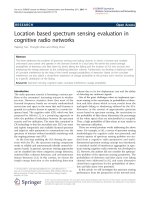
1.1 The opportunistic spectrum access model: The SU is allowed to access
the spectrum only if the PU is inactive. The shadowed area denotes
the spectrum occupied by the PU. The area with dash line denotes the
spectrum which could be utilized by the SU. . . . . . . . . . . . . . . 3
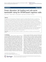
1.2 The spectrum sharing model: the SU can share the same spectrum
with the PU provided that its interference power at PU is lower than
a threshold. SU-Tx, SU-Rx, PU-Tx and PU-Rx denote the SU trans-
mitter, the SU receiver, the PU transmitter and the PU receiver, respec-
tively. Within the region S, the interference power caused by the SU
is larger than the interference power threshold. . . . . . . . . . . . . . 4
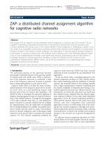
1.3 The overlay model: the SU transmitter has a priori knowledge of the
PU’s message. . . . . . . . . . . . . . . . . . . . . . . . . . . . . . . 6
2.1 The system model for CR SIMO-MAC. There are K SUs and N PUs.
The BS has N
r
receive antennas. Each SU is equipped with a single
transmit antenna. . . . . . . . . . . . . . . . . . . . . . . . . . . . . 16
x
LIST OF FIGURES
2.2 An example of power allocation results using CML water filling algo-
rithm. All seven SUs have the same transmit power and same power
gain, except that SU
4
’s power gain is 1.5 times the power gain for
others. The shadowed area for each subchannel denotes the power al-
located to the corresponding SU. . . . . . . . . . . . . . . . . . . . . 22
2.3 The relationship between the optimal solutions to the single constraint
sub-problems, SP3’ and SP4’. The solid slant line represents the in-
terference constraint for PU
1
, and the dash slant line represents the
constraint for PU
2
. p
(1)
, denoted by , indicates the optimal power
allocation for SP3’. p
(2)
, denoted by , represents the optimal power
allocation for SP4’. . . . . . . . . . . . . . . . . . . . . . . . . . . . 33
2.4 Two sample results show the convergence behavior of power vectors
for SUs using the DMCPA algorithm. represents a power vector of
an iterative step in solving SP3, and it satisfies PU
1
’s interference con-
straint. represents a power vector of an iterative step in solving SP4,
and it satisfies PU
2
’s interference constraint. The arrows represent the
directions of the power vector evolution. . . . . . . . . . . . . . . . 38
2.5 Achievable sum-rate vs the ratio of l
2
/l
1
using the CML water filling
algorithm for different numbers of K and N
r
: one PU and
¯
P
i
= 20 dB. 40
2.6 Effect of PU interference on the achievable sum-rate of the CR SIMO-
MAC: one PU, l
2
/l
1
= 4, N
r
= 6,
¯
P
i
= 20 dB and ˇp
1
= 10 dB. . . . . 41
2.7 Achievable sum-rate vs the ratio of l
2
/l
1
for perfect and estimated ma-
trix G: one PU, N
r
= K = 6 and
¯
P
i
= 2 0 dB. Robust design with 1
dB and 2 dB margins are also considered. . . . . . . . . . . . . . . . 42
2.8 Outage probability for interference power to PU: one PU, l
2
/l
1
= 5,
N
r
= K = 6 and
¯
P
i
= 20 dB. . . . . . . . . . . . . . . . . . . . . . 43
xi
LIST OF FIGURES
2.9 Achievable sum-rate vs transmit power using the CML water filling
algorithm for different l
2
/l
1
: one PU and K = N
r
= 4. . . . . . . . . 43
2.10 Achievable sum-rate vs the ratio of l
(2)
2
/l
1
under different constraints:
two PUs, K = N
r
= 3, l
(1)
2
/l
1
= 3 and
¯
P
i
= 20 dB. . . . . . . . . . . 44
2.11 Maximum achievable SINR versus the sum-power using the DMCPA
algorithm: one PU and K = N
r
= 3. . . . . . . . . . . . . . . . . . . 45
2.12 Maximum achievable SINR versus the ratio of l
(1)
2
/l
1
using the DM-
CPA algorithm: two PUs, K = N
r
= 3, l
(2)
2
= 2l
(1)
1
and
¯
P
i
= 20
dB. . . . . . . . . . . . . . . . . . . . . . . . . . . . . . . . . . . . . 46
3.1 The system model for CR MIMO-BC. There are K SUs and one PUs.
The BS has N
t
transmit antennas, each SU is equipped with N
r
receive
antennas, and the PU is equipped with a single receive antenna. . . . . 50
3.2 The system models for (Pc) and (Pd), where q
t
and q
u
are constant,
and R
o
= gg
†
. . . . . . . . . . . . . . . . . . . . . . . . . . . . . . 54
3.3 The flow chart for the SIPA algorithm, where S
b
i,(n)
and S
n
i,(n)
denote
the transmit covariance matrices of SU
i
for the BC and MAC at the
nth step, respectively. . . . . . . . . . . . . . . . . . . . . . . . . . . 67
3.4 Comparison of the optimal achievable rates obtained by the DIPA and
the water-filling algorithm in a MIMO channel (N
t
= N
r
= 4, K = 1
and
¯
P =10 dB). . . . . . . . . . . . . . . . . . . . . . . . . . . . . . 71
3.5 Convergence behavior of the DIPA algorithm (K = 20 and
¯
P = 10 dB). 71
3.6 Convergence behavior of the SIPA algorithm (N
t
= 5, K = 5, N
r
= 3,
w
1
= 5, and w
i
= 1, for i = 1). . . . . . . . . . . . . . . . . . . . . . 72
3.7 The convergence behavior of the sum power at the BS and the inter-
ference at the PU for the SIPA algorithm (N
t
= 5, K = 5, N
r
= 3,
w
1
= 5, and w
i
= 1 with i = 1). . . . . . . . . . . . . . . . . . . . . 73
xii
LIST OF FIGURES
3.8 Achievable sum rates versus sum power in the single PU case and the
case with no PU (N
t
= 5, K = 5, N
r
= 3). . . . . . . . . . . . . . . 73
4.1 The system model for CR MISO channel. There are a N-antenna SU-
Tx, a single antenna SU-Rx, and a single antenna PU. . . . . . . . . . 77
4.2 The geometric explanation of Lemma 4.4. The ellipse is the projection
of g = {g|(g − g
0
)
H
R
−1
(g − g
0
) = ǫ} on the plane spanned by
ˆ
g
//
and
ˆ
g
⊥
. . . . . . . . . . . . . . . . . . . . . . . . . . . . . . . . . . 82
4.3 The geometric explanation of problem P3. The circle is the projection
of g = {g|g −g
0
2
= ǫ} on the plane spanned by
ˆ
g
//
and
ˆ
g
⊥
. . . . 87
4.4 Comparison of the results obtained by the SOCP algorithm and Algo-
rithm 3. . . . . . . . . . . . . . . . . . . . . . . . . . . . . . . . . . 96
4.5 Comparison of the results obtained by the SOCP algorithm and Algo-
rithm 5. . . . . . . . . . . . . . . . . . . . . . . . . . . . . . . . . . 96
4.6 Effect of l
2
/l
1
on the achievable rate of the CR network (ǫ = 1, N =
3). (1)
¯
P = 10 dB; (2)
¯
P = 8 dB; (1)
¯
P = 6 dB. . . . . . . . . . . . . . 97
4.7 Comparison of the rate under different constraints of (P1). (i) the
maximal rate subject to interference constraint and transmit power con-
straint simultaneously; (ii) the maximal rate subject to a single transmit
power constraint; (iii) the maximal rate subject to a single interference
constraint. . . . . . . . . . . . . . . . . . . . . . . . . . . . . . . . . 98
5.1 The system models: (a) the MISO CR channel with K single-antenna
PUs; and (b) the MISO secrecy channel with K single-antenna eaves-
droppers. . . . . . . . . . . . . . . . . . . . . . . . . . . . . . . . . 102
5.2 Comparison of the secrecy rate by Algorithm 1 (A1) and that by the P-
SVD algorithm for the MISO secrecy channel with N = 4 and K = 2
single-antenna eavesdroppers. . . . . . . . . . . . . . . . . . . . . . 116
xiii
LIST OF FIGURES
5.3 Illustration of the function min
i=1,2
F
i
(Γ
1
, Γ
2
). . . . . . . . . . . . . 116
5.4 Comparison of the secrecy capacity by Algorithm 2 and the secrecy
rate by the P-SVD algorithm for M = N = 4 and K = 1 single-
antenna eavesdropper. . . . . . . . . . . . . . . . . . . . . . . . . . . 117
5.5 The value of the function F (Γ) for M = N = 4, K = 1 single-antenna
eavesdropper, and
¯
P = 5 dB. . . . . . . . . . . . . . . . . . . . . . . 118
5.6 Comparison of the lower and upper bounds on the secrecy rate and the
secrecy rate by the P-SVD algorithm for the MISO secrecy channel
with N = 4, and K = 1 eavesdropper with N
e
= 2 receive antennas. . 119
xiv
List of Tables
2.1 Recursive Decoupled Power Allocation Algorithm for Two PUs (RDPA-
2). . . . . . . . . . . . . . . . . . . . . . . . . . . . . . . . . . . . . 26
2.2 Recursive Decoupled Power Allocation Algorithm for N PUs (RDPA-
N). . . . . . . . . . . . . . . . . . . . . . . . . . . . . . . . . . . . . 27
2.3 Decoupled Multiple-Constraint Power Allocation Algorithm (DMCPA). 37
3.1 Decoupled Iterative Power Allocation (DIPA) Algorithm. . . . . . . . 64
3.2 Subgradient Iterative Power Allocation (SIPA) Algorithm. . . . . . . 67
4.1 The algorithm for SP2. . . . . . . . . . . . . . . . . . . . . . . . . . 89
4.2 The algorithm for problem P3 in the case where two constraints are
satisfied simultaneously. . . . . . . . . . . . . . . . . . . . . . . . . 90
4.3 The complete algorithm for problem P3. . . . . . . . . . . . . . . . . 91
4.4 The algorithm for problem P4 in the case where two constraints are
satisfied simultaneously. . . . . . . . . . . . . . . . . . . . . . . . . 93
4.5 The complete algorithm for (P1). . . . . . . . . . . . . . . . . . . . 94
5.1 Algorithm for Problem (5.3). . . . . . . . . . . . . . . . . . . . . . . 109
xv
List of Notations
a lowercase letters are used to denote scalars
a boldface lowercase letters are used to denote column vectors
A boldface uppercase letters are used to denote matrices
(·)
T
the transpose of a vector or a matrix
(·)
H
the conjugate transpose of a vector or a matrix
E[·] the statistical expectation operator
I
M
the M × M identity matrix
1
M
the M × 1 vector with all elements being one
diag(x) the diagonal matrix with the diagonal elements being vector x
tr(·) the matrix trace operation
Rank(·) the matrix rank operation
|S| the determinant of a matrix S
R the field of real numbers
[x]
+
max(x, 0)
(·)
b
/(·)
m
the quantities associated with a BC or a MAC,
xvi
List of Abbreviations
BS Base Station
CR Cognitive Radio
DMCPA Decoupled Multiple-Constraint Power Allocation algorithm
CML Capped Multi-Level
DFE Decision Feedback Equalizer
MMSE Minimum Mean-Square-Error
PU/PU
n
Primary User/Primary User n
QoS Quality-of-Service
RDPA-2 (N) Recursive Decoupled Power Allocation algorithm with Two (N) primary users
SIMO Single-Input Multiple-Output
MISO multiple-input single-output
MIMO multiple-input multiple-output
SINR Signal-to-Interference-plus-Noise Ratio
SU/SU
i
Secondary User/Secondary User i
ZF Zero-Forcing
CSI channel state information
SOCP second order cone programming
BC broadcast channel
MAC multiple access channel
xvii
Abbreviations
IC interference channels
SU-Tx SU transmitter
SU-Rx SU receiver
PU-Tx PU transmitter
PU-Rx PU receiver
CSCG circularly symmetric complex Gaussian
SIC successive interference cancelation
DPC dirty paper coding
RV random variable
xviii
Chapter 1
Introduction
Traditional spectrum regulation is based primarily on the command-and-control strat-
egy that assigns users to prescribed frequency bands, and restricts the potential users to
dynamically access the allocated radio spectrum. In a report published by the Federal
Communications Committee (FCC) [1], it has been shown that a significant amount of
the licensed radio spectrum is unused for 90% of time in the United States. Similar
observations have been made in other countries [2]. This static spectrum allocation
policy, together with the rapid deployment of various wireless services, leads to in-
creasing scarcity and congestion in the radio spectrum. Cognitive Radio (CR) that
allows the secondary (unlicensed) users to opportunistically or concurrently access the
licensed spectrum, show a great potential to improve the spectrum utilization [3,4].
This thesis investigatesthe resource optimization problems for three multi-antenna
based CR channels, including the CR single-input multiple-output multiple access
channels (SIMO-MAC), CR multiple-input multiple-output broadcast channels (MIMO-
BC), and CR multiple-input multiple-output (MISO) channels, and applies the resource
allocation results of CR MIMO channels to solve the capacity computation problem for
secrecy MIMO channels. In this chapter, we briefly introduce the recent development
and challenges of CR research, provide overviews on resource allocation for multi-
1
1.1 Cognitive Radio Models
antenna systems and secrecy communication systems, and present the contributions
and organization of this thesis.
1.1 Cognitive Radio Models
According to the definition in [4], CR is an intelligent wireless communication system
that is aware of its surrounding environment, adapts its transmission to the electromag-
netic environment, and improves the utilization efficiency of the radio spectrum. When
a CR is operating in a spectrum allocated to a primary user (PU), the CR is also called
the secondary user (SU). According to the capability of the SU in obtaining its sur-
rounding spectrum environment, the CR models can be classified into three categories:
the opportunistic spectrum access model, the spectrum sharing model, and the overlay
model. In the opportunistic spectrum access model, the SU has the lowest capability
in understanding its radio spectrum environment, i.e., it can only detect whether the
PU is on or off. If the SU finds that the spectrum is unoccupied by the PU, then the
SU can access this spectrum; otherwise, it cannot. In spectrum sharing model, the SU
regulates its transmission power such that the caused interference power at the PU is
lower than one threshold. In this case, the SU can access the spectrum even if the PU
is active. In overlay model, the SU is assumed to have a priori knowledge of the PU’s
messages. With that, the SU transmitter is able to send messages to its own receiver
and, at the same time, compensate for the resultant interference to the PU by assisting
the PU transmission.
1.1.1 The Opportunistic Spectrum Access Model
In opportunistic spectrum access model, the SUs are allowed to access the spectrum
only if it is not being used by the PUs as shown in Fig. 1.1. The key point in this model
2
1.1 Cognitive Radio Models
is to accurately detect the existence of the PUs, and the process to detect the PU’s ac-
tivity is termed as spectrum sensing. Spectrum sensing is one of the most fundamental
elements in a CR due to its crucial role in discovering spectrum opportunities. There
Frequency
PU
PU
PU PU
PU
PU
Time
Frequency
SU
SU SU
SU
Time
Figure 1.1: The opportunistic spectrum access model: The SU is allowed to access the
spectrum only if the PU is inactive. The shadowed area denotes the spectrum occupied
by the PU. The area with dash line denotes the spectrum which could be utilized by
the SU.
are several well-known conventional spectrum sensing algorithms, including the en-
ergy detection [5], matched filter [6–9], and feature detection [10,11]. Recently, there
are several new algorithms proposed for CR spectrum sensing, such as the eigenvalue
based algorithm [12,13] and the covariance based algorithm [14,15]. These spectrum
sensing algorithms usually rely on the local observations of a single SU. However, us-
ing the observations from a single SU might result in a hidden terminal problem [16],
with which the detection for PU may fail due to the shadowing. An efficient approach,
which is termed as cooperative spectrum sensing [16–20], is to have several SUs to co-
operate with each other for detecting the presence of the PU. If the SUs span a distance
that is larger than the correlation distance of the shadowing fading, it is unlikely that
all of them are under a deep shadow simultaneously. Thus, cooperative sensing has
better PU detection performance with the cost of additional operations and overhead
traffic.
3
1.1 Cognitive Radio Models
In order to protect the PUs, from medium access perspective, each medium access
control frame needs to have one sensing slot to sense the PU’s activity and one data
transmission slot for SU transmission in case the spectrum is found to be available.
The longer duration of the sensing slot, the better performance of the PU detection,
and thus the better protection to PUs. However, the longer sensing slot leads to the
shorter transmission time, and thus the lower SU throughput. The tradeoff between the
sensing time and the SU throughput was studied in [21].
1.1.2 The Spectrum Sharing Model
Figure 1.2: The spectrum sharing model: the SU can share the same spectrum with the
PU provided that its interference power at PU is lower than a threshold. SU-Tx, SU-
Rx, PU-Tx and PU-Rx denote the SU transmitter, the SU receiver, the PU transmitter
and the PU receiver, respectively. Within the region S, the interference power caused
by the SU is larger than the interference power threshold.
In spectrum sharing model, the SU is allowed to transmit simultaneously with the
PU provided that the interferences from the SU to the PU will not cause the resultant
4
1.1 Cognitive Radio Models
performance loss of PU to an unacceptable level. As shown in Fig. 1.2, the SU should
regulate its transmission power such that the caused interference at the PU is lower
than a threshold, which is called interference power constraint [22–24]. To achieve
this power constraint, the SU may also need to have the channel state information
(CSI) of the channel from the SU transmitter to the PU receiver.
To enable the spectrum sharing, dynamic resource allocation becomes crucial,
whereby the transmit power, bit-rate, bandwidth, and antenna beam of the CR need
to be dynamically adjusted based upon the CSI available at the CR transmitter. A
lot of existing studies for spectrum sharing model focus on the resource allocation to
optimize the performance of the SU networks [25–28].
For the single-antenna spectrum sharing CR fading channels, the power allocation
problem to achieve the ergodic/outage capacity has been studied in [29] under the aver-
age/peak interference power constraint, and in [30,31] under the combined interference
power and transmit power constraints. It has been shown in [32] that the average in-
terference power constraint is superior over the peak interference power constraint in
terms of maximizing the achievable ergodic capacities of both PU and SU.
In the past decade, multi-antenna communication systems have received consider-
able attention due to their capability to achieve many desirable functions, including the
interference suppression for multi-user transmissions [33], the capacity gain without
bandwidth expansion [34], and the diversity gain via space-time coding [35]. In ad-
dition to achieve the above functions, in CR networks, multi-antennas can be utilized
to suppress the interference to the PU. Transmit optimization for a single secondary
MIMO/MISO link in a CR network under interference power constraint is considered
in [36]. Multi-antennas were exploited at the secondary transmitter to optimally trade-
off between throughput maximization and interference avoidance. However, the role
of multi-antennas in multi-user CR systems is not completely understood yet. More-
over, it is unclear how to fully exploit the spatial degrees of freedom provided by the
5
1.1 Cognitive Radio Models
Genie
PU message
SU message
PU receiver
SU receiver
PU transmitter
SU transmitter
Figure 1.3: The overlay model: the SU transmitter has a priori knowledge of the PU’s
message.
multi-antenna SUs.
1.1.3 The Overlay Model
In overlay CR model, the SU is assumed to have perfect a priori knowledge on the mes-
sage being transmitted by the PU, which is illustrated in Fig. 1.3. Thus, the SU can
allocate part of its power for secondary transmission and the rest to assist the primary
transmission. Most of the studies on the overlay CR model are based on information
theory [37–43]. Complex coding schemes that including cooperative coding, collabo-
rative coding, and dirty paper coding, have been developed to improve the achievable
rate of the CR channel. Moreover, the power allocation problem to achieve the capacity
of overlay CR MIMO channel has been studied in [44]. The proposed power alloca-
tion scheme therein has been proved to be optimal under certain conditions. In [45],
recent results for overlay CR have been summarized from an information-theoretic
perspective.
6