Brillouin scattering investigation of nanomagnetic structures
Bạn đang xem bản rút gọn của tài liệu. Xem và tải ngay bản đầy đủ của tài liệu tại đây (6.34 MB, 108 trang )
BRILLOUIN SCATTERING INVESTIGATIONS OF
NANOMAGNETIC STRUCTURES
WANG ZHIKUI
NATIONAL UNIVERSITY OF SINGAPORE
2008
BRILLOUIN SCATTERING INVESTIGATIONS OF
NANOMAGNETIC STRUCTURES
WANG ZHIKUI (B. Sc.)
A THESIS SUBMITTED
FOR THE DEGREE OF DOCTOR OF PHILOSOPHY
NATIONAL UNIVERSITY OF SINGAPORE
2008
i
ACKNOWLEDGMENTS
First of all, I would like to express my sincere gratitude and appreciations to
my supervisors, Prof. KUOK Meng Hau and Prof. NG Ser Choon for their unfailing
guidance and support throughout this project. Special thanks to Asst. Prof. LIM Hock
Siah for his advice and discussion.
Thanks also to other lab fellows for their help. Lastly, I would like to thank my
family for their constant support.
ii
Table of Contents
Acknowledgement…………………………………………………… i
Table of Contents………………………………………………………ii
Summary……………………………………………………………….iv
List of Figures………………………………………………………….vi
Publications…………………………………………………………….x
Chapter 1 Introduction……………………………………………1
1.1 Introduction
1.2 Units
1.3 Structure of this theses
Chapter 2 Spin Waves……………………………………………7
2.1 Introduction
2. 2 Magnetostatic theory
2.2.1 Magnetostatic spin waves in a ferromagnetic slab
2.2.2 Magnetostatic spin waves in infinite long cylinders
2. 3 Dipole-Exchange spin wave theory for cylinders
2.3.1 Dipole-exchange spin waves in infinitely long single cylinders
2.3.2 Collective spin waves in arrays of cylinders
2. 4 Experimental techniques for spin wave
Chapter 3 Brillouin Light Scattering ………………… …… 30
3.1 Introduction
3.2 Kinematics of Brillouin scattering
3.3 Scattering mechanism
3.4 Experimental Setup
3.5 Instrumentation
3.5.1 Laser
3.5.2 Multi-pass Tandem Fabry-Perot Interferometer
iii
3.5.3 Photon Detector
3.5.4 Electromagnet
3.6 Analysis of Brillouin Spectrum
Chapter 4 Spin Wave Quantization in Ni Nanowires … …44
4.1 Introduction
4.2 Experiments
4.3 Results and analysis
4.4 Conclusions
Chapter 5 Collective Spin Waves in FeCo Nanowire Arrays …….62
5.1 Introduction
5.2 Sample fabrication and characterization
5.3 BLS experiments
5.4 Results and discussions
5.5 Conclusions
Chapter 6 Spin Dynamics of High Aspect Ratio Ni Nanorings …78
6.1 Introduction
6.2 Experiments
6.3 Results and discussions
6.4 Conclusions
Chapter 7 Conclusion…………………………………………… 92
iv
SUMMARY
This PhD research focuses on the Brillouin light scattering studies of magnons in
nanomagnets with cylindrical symmetry. The spin dynamics of three different samples,
viz. Ni nanowire arrays, close packed FeCo nanowire arrays and high aspect ratio Ni
nanorings, have been investigated.
In Chapter 1, a brief review of the studies on magnetic nanostructures and
objectives of the present study are presented. Chapter 2 gives the spin wave theory,
especially that on systems with cylindrical symmetry. Brief introduction on Brillouin
light scattering and instrumentation is presented in Chapter 3.
The observation of bulk spin wave quantization in Ni nanowires is presented in
Chapter 4. This Brillouin study reveals that the quantization effect of bulk spin waves
occurs when the diameter of the nanowires falls below 50 nm, and that both the
frequency differences and the frequencies of such confined modes increases when the
diameter of the nanowires decreases. The analysis based on the dipole-exchange theory
indicates that the discrete modes observed are a consequence of the quantization of bulk
spin waves due to confinement by the small cross section of the nanowires. Besides the
spin dynamics in single magnetic nanowires, the depression of value of spin wave
stiffness parameter suggests that knowledge of the interactions between the nanowires is
also of great importance at the high packing density required for quantum nanomagnetic
data storage.
v
Studies on the interactions between nanowires are presented in Chapter 5.
Brillouin measurements were made to investigate the spin dynamics of high-density 2-D
ordered Fe
48
Co
52
nanowire arrays, with various interwire spacings, as a function of
longitudinally applied magnetic field. Interpretation of the experimental data was
achieved by the Arias-Mills theory for collective spin waves in arrayed wires. It is found
that at each applied magnetic field value, the influence of neighboring nanowires is
manifested as a depression of the frequency of the lowest collective spin wave mode
relative to that of the isolated nanowire. This frequency depression becomes
progressively more pronounced with decreasing interwire spacing. These results provide
clear conclusive evidence of collective magnetic excitations in 2-D ordered arrays of
ferromagnetic nanowires.
Chapter 6 reports the study of spin dynamics of high aspect ratio Ni nanorings
using Brillouin spectroscopy. The experimental data were analyzed based on a
generalization of the Arias-Mills macroscopic dipole-exchange theory for long cylinders
in longitudinally applied magnetic field. The absense of a spin wave peak for applied
magnetic fields below 0.05 T suggests a transition of physical properties, which is in
accord with a transition from an aligned “bamboo” state to a “twisted bamboo” state,
predicted by microscopic simulations.
Chapter 7 summarizes the conclusions drawn from the three projects undertaken
in this PhD research.
vi
List of Figures
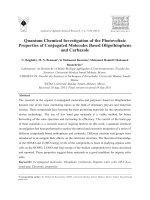
Fig 1.1 Traditional longitudinal (left) and new perpendicular recording (right).
Fig 2.1 Semiclassical representation of spin wave in a ferromagnet: (a) the ground
state (b) a spin wave of precessing spin vectors (viewed in perspective) and (c) the
spin wave showing a complete wavelength.
Fig 2.2 A ferromagnetic slab in an applied magnetic field H
0
.
Fig 2.3 A y-z plane showing the possible direction of propagation of the surface spin
wave, with reference to the critical angle,
c
φ
. The magnetic field is applied in the z
direction.
Fig 2.4 An infinitely long ferromagnetic cylinder in a constant applied magnetic field
H
0
and cylindrical coordinate system.
Fig 2.5 Mode profiles of a single isolated ferromagnetic cylinder for azimuthal
quantum number n = 1 and 2. The arrows represent the orientation and magnitude of
the dynamical magnetization and the gray scale depicts the variation of the magnetic
potential.
Fig 2.6 Coordinate system and quantities used in the multiple scattering theory.
Fig 2.7 Mode profiles of a three-wire array arranged in a shape of an equilateral
triangle. The arrows represent the orientation and magnitude of the dynamical
magnetization and the gray scale displays the variation of the magnetic potential. (a)
Lowest-frequency and (b) next lowest-frequency collective modes.
Fig 3.1 Scattering geometry showing the incident and scattered light wavevectors k
i
and k
s
; the surface and bulk magnon (phonon) wavevectors q
S
and q
B
.
θ
i
and
θ
s
are the
angles between the out going surface normal and the respective incident and scattered
light. (The plane which contains the wavevector of the scattered light and the surface
normal of the sample is defined as the scattering plane.)
Fig 3.2 Kinematics of (a) Stokes and (b) anti-Stokes scattering events occurring in
Brillouin scattering from bulk magnon.
Fig 3.3 Schematics of BLS set-up in the 180°-backscattering geometry.
Fig 3.4 The translation stage allowing automatic synchronization scans of the Fabry-
Perot tandem interferometer.
Fig 3.5 Control panel of the electromagnet with the field set at 0.60 T.
vii
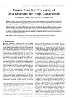
Fig 3.6 An example of spectral-fitting of a Brillouin spectrum using the Renishaw
program. The yellow curve indicates the experimental data red lines are due to the
quadratic background and four Lorentzian peaks. The resulting fitted spectrum is
shown as cyan curve. By reviewing the fitting results, information such as frequency
(center of the Lorentzian peak), intensity (area of the Lorentzian peak) and linewidth
can be obtained.
Fig 3.7 An example of spectra-fitting of a Brillouin spectrum using the PeakFit
program. The experimental data, background are shown as dots and yellow curve
respectively. The green, yellow and white lines at the bottom are the Lorentzian peaks
obtained. The resulting spectrum is show as the a grey curve.
Fig 4.1 Schematic diagram describing the fabrication of a highly ordered nickel
nanowire arrays: 1) Porous alumina obtained in the first anodization 2) Porous
alumina was removed and regular hexagonal texture of pore tips remained. 3) Highly
ordered alumina pore structure obtained by a second anodization. 4) The barrier layer
was thinned and the pores were widened. 5) Two current-limited anodization steps
were used for further thinning of the barrier layer and dendrite pore formation
occurred at the barrier layer. 6) Pulsed electrodeposition of nickel into the pores.
[After Kornelius Nielsch et al. Ref. 14]
Fig 4.2 Structure of the hexagonally ordered array of nickel nanowires. ( a) Schematic
of 1-µm thick Al
2
O
3
matrix containing nickel nanowires. (b) SEM micrograph
showing top view of membrane with interware (center to center) separation of 100
nm.
Fig 4.3 SQUID-Hysteresis loops of the Ni nanowire arrays with periodicity of Dint =
100 nm and a pore diameter D
P
= 55 nm (a), D
P
= 40 nm (b) D
P
= 30 nm (c) and Dint =
65 nm, D
P
= 25 nm. [After Kornelius Nielsch et al. Ref. 14]
Fig. 4.4 Schematic Brillouin scattering geometry.
Figure 4.5 Brillouin anti-Stokes spectrum of the 30 nm diameter nickel nanowire
sample in zero applied magnetic field. Experimental data are denoted by dots. The
peaks are due to the three bulk spin waves. The spectrum is fitted with Lorentzian
functions (solid blue curves) and a background (dashed blue curve); the full fitted
spectrum is shown in red.
Fig 4.6 Variation of bulk spin wave frequencies with nanowire radius in zero applied
magnetic field. The experimental data points, for each radius, correspond to the three
values of the azimuthal quantum number m. The solid curves represent the respective
best fits of the experimental data with Eq. (4.3). The diamond denotes the frequency
of the bulk spin wave for bulk nickel [19].
Fig 4.7 Brillouin spectra of the 30 nm diameter nickel nanowire sample in 0.04 T
transversely applied magnetic field. The incident angle is varied from 30° to 70°.
Fig 4.8 Variation of bulk spin wave frequencies with transversely applied magnetic
viii
field, of a 30 nm diameter nickel nanowire.
Fig 4.9 Variation of bulk spin wave frequencies with transversely applied magnetic
field, of a 30 nm diameter nickel nanowire. Our experimental Brillouin data are
shown as symbols and the solid lines correspond to the calculations using Eq. (4.7).
The dashed lines corresponds to the splitting of the lowest-energy mode whose
investigation is beyond the scope of this thesis. [After Ref. 23]
Fig 5.1 Magnetic field dependence of the frequencies of the three lowest-lying spin
wave modes in a 2-D hexagonal array of permalloy nanowires. The azimuthal
quantum numbers m = 1, 2 and 3 label the spin wave modes of an isolated permalloy
nanowire. The experimental data are denoted by squares and dots while the calculated
frequencies are represented by solid (array of nanowires) and dashed (isolated
nanowire) lines. [After Liu et al. Ref. 11]
Fig 5.2 SEM images of an alumina template filled with Fe
48
Co
52
. The diameter of the
wires (pores) is 20 nm and interwire (interpore) separation s = 50 nm.
Fig 5.3 SQUID-Hysteresis loops of the FeCo nanowire arrays with diameter of 20 nm
and interwire separation (center to center) s = 50 nm (a), 40 nm (b) 30 nm (c).
[Measured by Dr. H. L. Su]
Fig 5.4 Brillouin spectra of a 20nm-diameter Fe
48
Co
52
nanowire array with interwire
separation s = 50 nm recorded at various longitudinal magnetic fields.
Fig 5.5 Brillouin spectra, recorded at 0.6 T, of 20nm-diameter Fe
48
Co
52
nanowire
arrays with respective interwire separations s = 30, 40, 50 and 55 nm.
Fig 5.6 Magnetic field dependence of the frequencies of the lowest-energy spin wave
in the four Fe
48
Co
52
nanowire arrays. Experimental data are denoted by symbols for
the arrays with interwire separations s = 30 nm (square), 40 nm (circle), 50 nm
(triangle) and 55 nm (star). The experimental errors are smaller than the symbols
shown. Theoretical collective spin wave mode frequencies are represented by lines: s
= 30 nm (dashed-dotted line), 40 nm (dashed line), 50 nm (dotted line) and 55 nm
(solid line).
Fig 5.7 Frequencies of the spin waves in Fe
48
Co
52
nanowire arrays as a function of
interwire separation, at a longitudinal magnetic field of 0.6 T. Experimental data are
denoted by dots with error bars. Calculated frequencies of the two lowest-energy
collective spin wave modes are represented by solid lines. Corresponding predicted
frequencies for the isolated single nanowire are shown as horizontal dashed lines.
Fig 6.1 Micromagnetic simulations of the onion-to-vortex transition in an asymmetric
ring. (a) and (f) are equilibrium states; (b)-(e) are the intermediate magnetic states
during switching. [After Rothman et al. Ref. 10]
Fig 6.2 Schematic views of method for fabricating Ni nanorings. (a) Ni is evaporated
down to AAO mask on a silicon substrate, array of Ni dots (black) obtained, (b) Ni
around the pore walls after ion-etching and (c) Ni nanorings array after AAO mask
ix
being removed [After K. L. Hobbs et al. Ref. 15].
Fig 6.3 SEM micrograph of the hexagonal array of the high-aspect-ratio nickel
nanorings.
Fig 6.4 Brillouin spectra of the nickel nanoring sample in varies of longitudinally
applied magnetic field. The incident angle is varied from 60°.
Fig 6.5 Brillouin spectrum of a nickel nanoring array in a 0.8 T magnetic field applied
parallel to the symmetry axis of the rings. Experimental data are denoted by dots. The
spectrum is fitted with a Lorentzian function (dotted curve) and a background (dashed
curve), and the resulting fitted spectrum is displayed as a solid curve.
Fig 6.6 Magnetic field dependence of the frequencies of spin waves in a nickel
nanoring. Measured frequencies are represented by closed dots, while calculated ones
by open circles (micromagnetic simulations) and a solid curve (analytical equation
ω
=
γ
[H
t
(4
π
M
s
+ H
t
)]
1/2
).
Fig 6.7 Simulated magnetization distributions (H
0
= 5 mT) for a nickel nanoring in
the ‘twisted bamboo’ phase. (a) A cross-section containing the ring axis, and (b) top,
(c) middle and (d) bottom cross-sections normal to the ring axis (viewed along the -
H
0
direction).[After Ref. 20]
x
Publications
I. International Journals:
1. Z. K. Wang
, H. S. Lim, S. C. Ng, B. Özyilmaz and M. H. Kuok, “Brillouin Study of
Low-Frequency Acoustic Phonons in Few-layer Graphene”. (manuscript submitted).
2. Z. K. Wang,
H. S. Lim, V. L. Zhang, J. L. Goh, S. C. Ng, M. H. Kuok, H. L. Su and S.
L. Tang, “Collective spin waves in high-density two-dimensional arrays of FeCo
nanowires”, Nano Lett. Vol. 6 (2006) 1083
.
3. Z. K. Wang, H. S. Lim, H. Y. Liu, S. C. Ng, M. H. Kuok, L. L. Tay, D. J. Lockwood,
M. G. Cottam, K. L. Hobbs, P. R. Larson, J. C. Keay, G. D. Lian, and M. B. Johnson,
“
Spin waves in nickel nanorings of large aspect ratio”, Phys. Rev. Lett. Vol. 94
(2005) 137208.
4. Z. K. Wang, M. H. Kuok, S. C. Ng, D. J. Lockwood, M. G. Cottam, K. Nielsch, R. B.
Wehrspohn, and U. Gösele, “Spin-Wave Quantization in Ferromagnetic Nickel
Nanowires”, Phys. Rev. Lett., Vol. 89 (2002) 027201 1-3.
5. Z. K. Wang
, M. H. Kuok, S. C. Ng, H. J. Fan, D. J. Lockwood, K. Nielsch and
R. B. Wehrspohn, “Magnetic and acoustic excitations in confined nickel nanowires”,
Material Physics and Mechanics, Vol. 4, No. 1 (2001) 22 – 24.
…………………………………………………….
6. Y. Li, H. S. Lim, Z. K. Wang
, S. C. Ng and M. H. Kuok, “Micro-Brillouin Study of
the Eigenvibrations of Single Isolated Polymer Nanospheres”, J. Nanosci.
Nanotechnol. (Manuscript accepted).
7. Y. Li, H. S. Lim, S. C. Ng, Z. K. Wang
and M. H. Kuok, “Selection rules for Brillouin
light scattering from eigenvibrations of a sphere”, Chem. Phys. Lett. Vol. 461 (2008)
111.
8. C. G. Tan, H. S. Lim, Z. K. Wang
, S. C. Ng, M. H. Kuok, S. Goolaup, A. O. Adeyeye
and N. Singh, "Quantization of spin waves in oval shaped nanorings", J. Mag. Mag.
Mat. Vol. 320 (2008) 475.
xi
9. T. M. Nguyen, M. G. Cottam, H. Y. Liu, Z. K. Wang, S. C. Ng, M. H. Kuok, D. J.
Lockwood, K. Nielsch and U. Gosele, “Spin waves in Permalloy nanowires:
important role of easy-plane anisotropy”, Phys. Rev. B Vol.73 (2006) 140402 (R).
10. Y. Li, H. S. Lim, S. C. Ng, Z. K. Wang
, M. H. Kuok, E. Vekris, V. Kitaev, F. C. Peiris,
and G. A. Ozin, “Micro-Brillouin scattering from a single isolated nanosphere”, Appl.
Phys. Lett. Vol. 88, (2006) 023112.
11. H. Y. Liu, Z. K. Wang
, H. S. Lim, S. C. Ng, M. H. Kuok, D. J. Lockwood, M. G.
Cottam, K. Nielsch, and U. Gösele, “Magnetic-field dependence of spin waves in
ordered permalloy nanowire arrays in two dimensions”, J. Appl. Phys. Vol. 98 (2005)
046103.
12. Y. Li, H. S. Lim, Z. K. Wang
, S. C. Ng and M. H. Kuok, “Confined acoustic modes in
nanoparticles” J. Phys. IV. Vol. 129 (2005) 51.
13. D. C. Crew, R. L. Stamps, H. Y. Liu, Z. K. Wang, M. H. Kuok, S. C. Ng, K. Barmak,
and J. Kim and L. H. Lewis, “
Light scattering from spin wave excitations in a
Co/CoPt exchange spring.
”, J. Mag. Mag. Mat. Vo l . 290-291 (2005) 530.
14. H. S. Lim, M. H. Kuok, S. C. Ng and Z. K. Wang, “Brillouin Observation of Bulk and
Confined Acoustic Waves in Silica Microspheres”, Appl. Phys. Lett. Vol. 84, (2004)
4182.
15. D. C. Crew, R. L. Stamps, H. Y. Liu, Z. K. Wang
, M. H. Kuok, S. C. Ng, K. Barmak,
and J. Kim and L. H. Lewis, “Spin wave excitations in exchange spring Co/CoPt thin
film bilayers”, J. Mag. Mat. Mag. Vol. 272-276 (2004) 273.
16. M. H. Kuok, H. S. Lim, S. C. Ng, N. N. Liu, and Z. K. Wang
, “Brillouin Study of The
Quantization of Acoustic Modes in Nanospheres”, Phys. Rev. Lett., Vol. 90 (2003)
255502.
II. International Conferences:
1. Z. K. Wang, Y. Li, H. S. Lim, S. C. Ng and M. H. Kuok, "Brillouin Studies of
Acoustic Phonon Confinement in Nanostructures". 15th International Conference on
Composite/Nano Engineering, 2007, Hainan, Haikou, China) (Invited Talk)
2. Z. K. Wang
, H. S. Lim, S. C. Ng, M. H. Kuok, S. L. Tang and H. L. Su, “Brillouin
Light Scattering investigation on acoustic waves in CoFe nanowire array”,
xii
International Conference on Materials for Advanced Technology, 2003, Singapore,
Symposium: Y.
3. Z. K. Wang, M. H. Kuok, S. C. Ng, D. J. Lockwood, M. Cottam, K. Nielsch, R. B.
Wehrspohn, H. Hofmeister
and U. Gösele, “Spin waves in ordered arrays of cobalt
nanowires”, International Conference on Materials for Advanced Technology, 2003,
Singapore, Symposium: N1.
……………………………………………
4. C. G. Tan, H. S. Lim, Z. K. Wang,
S. C. Ng, M. H. Kuok, S. Goolaup and A. O.
Adeyeye, "Quantized magnon modes in Ni
80
Fe
20
nanorings". International
Conference on Materials for Advanced Technologies, 2007, Singapore.
5. M. H. Kuok, Z. K. Wang,
H. S. Lim, S. C. Ng, J. L. Goh, H. L. Su and S. L. Tang,
“Spin Waves and Dynamic Coupling in 2-D Magnetic Nanowire Arrays”, 2006 MRS
Spring Meeting, San Francisco, USA, (Invited talk).
6. M. H. Kuok, Y. Li, H. S. Lim, Z. K. Wang
, S. C. Ng, H. L. Su and S. L. Tang,
“Brillouin studies of nanostructures”, Twelfth International Conference on
Composites/Nano Engineering (E - 12), (Invited talk), 2005, Tenerife, Spain.
7. H. Y. Liu, H. S. Lim, Z. K. Wang
, S. C. Ng and M. H. Kuok, “3-D Micromagnetic
Simulations of Magnetization Distributions in a Ni Nanotube” International
Conference on Materials for Advanced Technology, 2003, Singapore, Symposium: D.
8. K. Nielsch, R. B. Wehrspohn, U. Gösele, Z. K. Wang
, M. H. Kuok, S. C. Ng, D. J.
Lockwood, and M. G. Cottam, “Spin Dynamics in Nickel Nanowires Arrays”, 2002
MRS Fall Meeting, Symposium Q: Magnetoelectronics Novel Magnetic Phenomena
in Nanostructures, Boston (2002).
CHAPTER 1 Introduction
1
Chapter 1 Introduction
§ 1.1 Introduction
While the increase in magnetic storage density for hard disks has been 60-
100% per year since 1991, the predicted superparamagnetic limit, about 150 – 200
Gbit/in
2
, is almost reached [1, 2]. One approach to extend this storage density limit is
via the study on patterned perpendicular media, in which one bit of information
corresponds to one single domain nano-sized particle, a so-called nanomagnet. Since
each bit would be composed of a single high-aspect ratio particle, the area density of
these patterned media can, in principle, be much higher than that of conventional
longitudinal media (see Fig 1.1). One promising technique to obtain such nanomagnet
arrays is based on hexagonally arranged porous alumina templates. Highly ordered
magnetic nanowire arrays filled in alumina templates have been successfully
fabricated [3, 4].
Fig 1.1 Traditional longitudinal (left) and new perpendicular recording (right).
CHAPTER 1 Introduction
2
Another approach to extend the storage density limit is using the ring-
structured nanoparticles as recording media units. Such ring structure is proposed
because of the existence of vortex (flux-closed) states, in which the magnetization is
oriented circularly and for which stray magnetic fields are essentially absent [5, 6].
However, to use such nanomagnets as magnetic storage device with density as
high as 1 Terabit/in
2
, we have to consider the fundamental limits, which mainly arise
from thermal stability. Thus an understanding of the magnetic and thermal properties
of nanomagnets are of fundamental importance. Although many techniques have been
employed to study nanomagnets, most of them such as SEM, TEM, STM, AFM and
MFM, can only provide static information. In contrast investigations of the dynamical
properties of nanomagnets, especially experimental ones, are rare.
Brillouin light scattering (BLS) is a powerful tool for investigating both the
magnetic properties of small-sized samples [7-9]. For example, extensive studies on
spin waves in micron or submicron magnetic stripes and circular plates [9-11], as well
as in magnetic thin films [12, 13] and multilayers/superlattice [14, 15], have been
carried out using Brillouin scattering. A recent BLS study of micron size magnetic
rectangular 1-D arrays of wires was reported by C. Mathieu et al. [10], who observed
quantization of surface spin waves. If the size of the nanomagnets is decreased to tens
of nanometers, problems such as whether the surface spin waves can still be observed,
whether the bulk spin waves will be quantized when the dimension become even
smaller, and how will the interaction between the neighboring elements, in an array,
affect the spin wave frequency, will still need to be resolved.
To my knowledge, employing BLS method to study vertical arrayed
nanowires or nanorings had not yet been published elsewhere when this thesis project
was started. The main purpose of this thesis is to study the behavior of spin waves in
CHAPTER 1 Introduction
3
nanomagnets, especially in trying to observe one important phenomenon of waves –
quantization caused by confinement effect. Another purpose is to study the magnetic
interaction effects between the nano-elements, which are of great importance to the
applications of the nanomagnets.
It is hoped that the accurate BLS data reported in this thesis can be used as a
data source for the theorists to test their newly developed dynamic magnetic theories
on nano-size structures. And it is also hoped that some basic parameters measured in
this study can be helpful for the engineers to fabricate higher density magnetic storage
devices.
§ 1.2 Units
The unit systems of magnetism are fairly confusing, compare to other field of
physics. Several competing systems exist, in both CGS and MKS (SI). Besides the
unit system, the names of the quantities in the field of magnetism also vary widely,
for example, “Magnetic Field” could have the same meaning as “Magnetic Field
Strength” or as that of “Magnetic Induction”. Thus one has to do extensive detective
work to understand the exact meaning of an equation. Moreover, each unit system has
a special form of the fundamental magnetic equation, which shows the relationship
between magnetic flux density B, magnetic field H, and magnetization M. Three
common forms of basic equations in SI unit system are [16]:
B =
µ
0
H + M (1.1)
B =
µ
0
(H + M) (1.2)
B = H +
µ
0
M (1.3)
where
µ
0
is the magnetic permeability of free space. In CGS-Gauss unit system, the
basic equation is normally written as:
CHAPTER 1 Introduction
4
B = H + 4π M (1.4)
And in the CGS-EM (electromagnet) unit system:
B = H + M (1.5)
This thesis is written, as far as practice is concerned, using the CGS-Gauss
unit system and the fundamental magnetic equation used is Eq. (1.4). The author
chooses the CGS-Gauss unit system because most of the related references on spin
wave theory are using this unit system.
§ 1.3 Structure of this thesis
The contents of each chapter are briefly listed below:
Chapter 1 (this Chapter): A brief introduction is given; the purposes of this thesis are
stated; units used are clarified and structure of this thesis is listed.
Chapter 2: Basic theory of spin waves is presented; two kinds of structures, e. g. film
and cylinder are discussed in details.
Chapter 3: Introduction to Brillouin light scattering.
Chapter 4: The bulk spin wave quantization in Ni nanowires is studied by means of
BLS.
Chapter 5: The collective spin waves are studied. The interaction between the FeCo
nanowires in a close packed array is discussed.
Chapter 6: The BLS study on spin waves in 2D vertical array of nanorings is
presented.
Chapter 7: Conclusions.
References:
CHAPTER 1 Introduction
5
[1] R. L. White, J. Magn. Magn. Mater. 209 (2000) 1.
[2] H. F. Hamann, Y. C. Martin, and H. K. Wickramasinghe, Appl. Phys. Lett. 84
(2004) 810.
[3] K. Nielsch, F. Müller, A. P. Li, and U. Gösele, Adv. Mater. 12 (2000) 582.
[4] K. Nielsch, R. B. Wehrspohn, J. Barthel, J. Kirschner, U. Gösele, S. F. Fischer,
and H. Kronmuller, Appl. Phys. Lett. 79 (2001) 1360.
[5] S. P. Li, D. Peyrade, M. Natali, A. Lebib, Y. Chen, U. Ebels, L. D. Buda, and K.
Ounadjela, Phys. Rev. Lett. 86 (2001) 1102.
[6] F. J. Castano, C. A. Ross, C. Frandsen, A. Eilez, D. Gil, H. I. Smith, M. Redjdal,
and F. B. Humphrey, Phy. Rev. B. 67 (2003) 184425.
[7] M. G. Cottam and D. J. Lockwood, Light Scattering in Magnetic Solids, (Wiley,
New York, 1986).
[8] Y. Li, H. S. Lim, S. C. Ng, Z. K. Wang, M. H. Kuok, E. Vekris, V. Kitaev, F. C.
Peiris, and G. A. Ozin, Appl. Phys. Lett. 88 (2006) 023112.
[9] S. O. Demokritov, B. Hillebrands, and A. N. Slavin, Phys. Rep. 348 (2001)
441489.
[10] C. Mathieu, J. Jorzick, A. Frank, S. O. Demokritov, A. N. Slavin, B. Hillebrands,
B. Bartenlian, C. Chappert, D. Decanini, F. Rousseaux, and E. Cambril, Phys. Rev.
Lett. 81 (1998) 3968.
[11] J. Jorzick, S. O. Demokritov, B. Hillebrands, B. Bartenlian, C. Chappert, D.
Decanini, F. Rousseaux, and E. Cambril, Appl. Phys. Lett. 75 (1999) 3859.
[12] S. Subramanian, X. Liu, R. L. Stamps, R. Sooryakumar, and G. A. Prinz, Phys.
Rev. B 52 (1995) 10194.
[13] B. Hillibrands, P. Baumgart and G. Guntherodt, Phys. Rev. B 36 (1987) 2450.
[14] T. Blachowicz, Brillouin spectroscopy in crystal lattice (Silesian University of
CHAPTER 1 Introduction
6
Technology Press, Gliwice 2003).
[15] G. Gubbiotti, M. Kostylev, N. Sergeeva, M. Conti, G. Carlotti, T. Ono, A. N.
Slavin and A. Stashkevich, Phys. Rev. B 70 (2004) 224422.
[16] P. C. Scholten, J. Magn. Magn. Mater. 149 (1995) 57.
CHAPTER 2 Spin Waves
7
Chapter 2 Spin Waves
§ 2. 1 Introduction
Spin waves (or magnons) are low-lying excitations that exist in ordered
magnetic materials. The characteristics of the magnons in any particular magnetic
material depend on the nature of the interactions and type of magnetic material such
as ferromagnets, antiferromagnets, and ferrimagnets. In this thesis, only spin waves in
ferromagnets will be considered.
The concept of spin waves, as the lowest lying magnetic state above the
ground state, was introduced by Bloch [1] in 1930. He envisaged spin waves as slight
deviations of spins from their ground states, which propagate with a wavelike
behavior through the crystals. This dynamic effect was ignored in the mean field
theory, where the exchange interactions are replaced by a static effective field.
Bloch’s theory predicted that the magnetization of a ferromagnet at low temperatures
(T) should deviate from the zero-T value with a T
3/2
dependence, instead of the
exponential dependence given by mean field theory. Fig 2.1 shows a schematic view
of spin waves in a ferromagnet. For a ferromagnetic material, there is an interaction
between neighboring electronic spins, which gives rise to a parallel alignment at
ground state. With perturbation the spins will deviate slightly from their ground state
(Fig 2.1b), and this disturbance will propagate with a wavelike behavior (Fig 2.1c)
through the material.
CHAPTER 2 Spin Waves
8
The spin wave theory most widely used nowadays is the semi-classical
“dipole-exchange” spin wave theory which treats considers both dipole and exchange
interactions. To understand this theory, one can start either from a quantum
mechanical point of view by means of a Heisenberg model or from a classic point of
view by means of a magnetostatic theory. In this chapter, the magnetostatic theory
which considers only the long-range dipole energy will be introduced first, with a
discussion on the properties of spin waves in two specific geometries: (1) a film/slab,
which is the most widely studied structure and (2) an infinitely long cylinder, which is
a structure studied in this thesis. The exchange-dipole spin wave theory is then
discussed for the cylindrical geometry, by including the exchange energy term. The
theory of spin waves in an isolated cylinder is next extended to describe collective
spin wave modes in an array of cylinders.
(a)
(b)
(c)
Fig 2.1 Semiclassical representation of spin wave in a ferromagnet: (a) the ground
state (b) a spin wave of precessing spin vectors (viewed in perspective) and (c) the
spin wave showing a complete wavelength.
CHAPTER 2 Spin Waves
9
§ 2. 2 Magnetostatic theory
In the magnetostatic theory, the modes of spin waves are due to purely
magnetostatic forces arising from the externally applied magnetic field and the dipolar
fields of the sample magnetization. The forces due to exchange interaction and
electromagnetic induction may be ignored [2].
In the magnetostatic limit, Maxwell’s equations become
∇ × H = 0 (2.1a)
∇ ⋅ B = 0 (2.1b)
where H and B are the magnetic field and magnetic flux density, respectively.
The boundary conditions require the continuity of the normal component of B
and the tangential component of H at the sample surface, and these fields must
approach zero at large distances from the sample.
Let the applied magnetic field, H
0
, lie in the z direction. The magnetization
and magnetic field may be written as
M = M
0
i
z
+ me
-i
ω
t
(2.2)
H = H
i
i
z
+ he
-i
ω
t
(2.3)
where M
0
is the static magnetization and H
i
= H
i
i
z
is magnetic field inside the
magnetic material, i
z
is a unit vector in the z direction, m and h represent the
fluctuating components of the respective fields at angular frequency
ω
. Neglecting the
anisotropy field, H
i
= H
0
+ H
demag
, where H
0
is the applied magnetic field and H
demag
is the demagnetizing field. In the ferromagnetic medium (here |m |<< M
0
thus M
0
º|M| =M
s
, M
s
is the saturation magnetization). m lies mainly in the x-y plane thus m
z
is taken to be zero in the following discussion. However, h may have x, y and z
components.
Substituting Eqs. (2.2) and (2.3) into Eqs. (2.1) one can get
CHAPTER 2 Spin Waves
10
∇ × h = 0 (2.4a)
∇ ⋅ (h + 4πm) = 0 (2.4b)
Eq. (2.4a) permits the introduction of a scalar magnetic potential,
ψ
, such that h =
∇ψ
,
and Eq. (2.4b) becomes
∇
2
ψ
+ 4π
∇
⋅ m = 0 (2.5)
The equations of motion of magnetization (torque equations), neglecting energy
losses, are
()
d
dt
γ
=×
M
MB (2.6)
where
γ
is the gyromagnetic ratio. Substituting for M and B and retaining only the
linear terms in m and h, the equations of motion become
00
/[ ]
z
iMH
ω
γ
=− × −mihm. (2.7)
Using h =
∇ψ
, Eq. (2.7) can be written as
4
4
x
y
mi
x
y
mi
x
y
ψ
ψ
πκ ν
ψ
ψ
πνκ
∂
∂
=+
∂
∂
∂
∂
=− +
∂
∂
(2.8)
where
2222
Ω−Ω
Ω
=
Ω−Ω
Ω
=
HH
H
νκ
and
00
,.
44
i
H
H
M
M
ω
ππγ
Ω= Ω=
Substituting expressions (2.8) into Eq. (2.5), the potential inside the sample
satisfies
22 2
22 2
(1 ) 0.
ii i
xy z
ψψ ψ
κ
⎡⎤
∂∂ ∂
+++=
⎢⎥
∂∂ ∂
⎣⎦
(2.9)
CHAPTER 2 Spin Waves
11
Outside the sample, Laplace’s equation must be satisfied,
2
0.
e
ψ
∇= (2.10)
The equations up to this point apply to a sample of arbitrary shape having a
uniform internal field. We now consider two specific shapes: slab/film and infinitely
long cylinder.
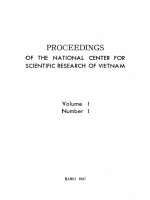
2.2.1 Magnetostatic spin waves in a ferromagnetic slab
Consider a particular geometry of a ferromagnetic slab of thickness s (in x-
direction), with infinite lateral extent and magnetized in its own plane (in z-direction)
as indicated in Fig 2.2.
For this geometry the demagnetizing factor N
z
= 0. Thus the internal field is
equal to the applied field, i.e. H
i
= H
0
. The boundary condition on the normal
component of
B requires
z
y
x
H
0
Fig 2.2 A ferromagnetic slab in an applied magnetic field
H
0
.
s
0
z
x
+s/2
-s/2