in flap surgery non invasive in vivo methodology to predict skin flap shrinkage
Bạn đang xem bản rút gọn của tài liệu. Xem và tải ngay bản đầy đủ của tài liệu tại đây (2.79 MB, 153 trang )
SKIN FLAP SURGERY –
NON-INVASIVE IN VIVO METHODOLOGY
TO PREDICT SKIN FLAP SHRINKAGE
LIM KENG HUI
NATIONAL UNIVERSITY OF SINGAPORE
2008
SKIN FLAP SURGERY –
NON-INVASIVE IN VIVO METHODOLOGY
TO PREDICT SKIN FLAP SHRINKAGE
LIM KENG HUI
(B. Eng., Imperial College, UK;
MS. Eng, Massachusetts Institute of Technology, USA)
A THESIS SUBMITTED
FOR THE DEGREE OF DOCTOR OF PHILOSOPHY
DEPARTMENT OF MECHANICAL ENGINEERING
NATIONAL UNIVERSITY OF SINGAPORE
2008
ACKNOWLEDGEMENT
I would like to thank my colleagues, Ho Hoan Nghia and Sujee Jeyapalina, who
worked closely with me in this project. Their valuable insights and industry have
helped me greatly. I would also like to thank James Rappel, Du Tiehua, Chew Chee
Meng and Peter Chen for their contributions and support. I would further like to thank
my supervisors, Teo Chee Leong and Lim Beng Hai for their advice.
Special thanks go to the staffs at the Controls and Mechatronics Lab, Mrs. Ooi, Ms
Tshin, Hamidah, Mr. Zhang and Mr. Yee. Their helpfulness and efficiency go a long
way in facilitating our work.
It has been fun working at the lab, and this is made possible by my friends there. I
hope we will remain close.
Finally, I dedicate this thesis to my lovely wife ZY and my parents. I thank them for
all their love, support and encouragement, and I hope to make them proud.
i
TABLE OF CONTENTS
SUMMARY vi
LIST OF TABLES viii
LIST OF FIGURES ix
LIST OF SYMBOLS xiv
Chapter 1 Introduction 1
1.1. Problem statement 1
1.2. Motivation 2
1.3. Objectives and scope of work 3
1.4. Organization of thesis 4
Chapter 2 Literature review 6
2.1. Introduction 6
2.2. Skin flap surgery 6
2.2.1. Skin flap composition 7
2.2.2. Skin flap shrinkage 8
2.2.3. Flap-defect matching problem 12
2.3. Biomechanical properties of skin 13
2.4. Skin measurement devices overview 16
2.4.1. Current devices 17
2.4.2. Standardization of measurement 19
2.5. Measurement of natural tension 20
2.5.1. Wrinkle test 20
2.5.2. Suction cup 21
2.5.3. Modified extensometer 22
2.6. Summary 24
Chapter 3 Instrumentation design 25
3.1. Introduction 25
3.1.1. Existing design concept 26
3.2. New design concept 27
3.3. Method – Hardware 28
3.3.1. Constructed device 28
3.3.2. Device attachment to skin 29
3.3.3. Instrumentation control 29
3.3.4. Articulated arm 31
ii
3.4. Method – Modeling 32
3.4.1. Finite element modeling 32
3.4.2. Modeling of residual peripheral forces 33
3.5. Method – Mechanical testing 37
3.5.1. Materials 37
3.5.2. In vitro experiment: Rubber strip 37
3.5.3. In vivo experiment: Rubber sheet 38
3.5.4. In vivo experiment: Pig skin 39
3.6. Results 40
3.6.1. Finite element analysis 40
3.6.2. Mechanical testing – Rubber 41
3.6.3. Modeling of residual peripheral forces - Rubber 42
3.6.4. Mechanical testing – Pig skin 44
3.6.5. Device contact pressure 45
3.7. Discussion 46
3.7.1. Effectiveness of shield pad design 46
3.7.2. Accuracy of residual peripheral force modeling 47
3.7.3. Standardization of measurement 49
3.8. Summary 50
Chapter 4 Skin measurement principles 51
4.1. Introduction 51
4.2. Non-invasive skin measurement 51
4.2.1. Deformation uniformity of skin thickness 54
4.3. Preconditioning of skin 55
4.4. Viscoelasticity 57
4.4.1. The effect of measurement strain rate 58
4.5. Standardization of measurement 59
4.6. Clinical trial on animal 60
4.6.1. Invasive determination of Langer’s line 61
4.7. Summary 62
Chapter 5 Prediction of Langer’s line 63
5.1. Introduction 63
5.2. Method – Imaging and mechanical testing 64
5.2.1. Materials 64
iii
5.2.2. Scanning electron microscopy 64
5.2.3. In vitro experiment: Leather 65
5.2.4. In vivo experiment: Human skin 65
5.2.5. In vivo experiment: Pig skin 66
5.3. Results and Discussion 67
5.3.1. Scanning electronic microscopy 67
5.3.2. Human skin and leather experiments 68
5.3.3. Method of predicting Langer’s line direction 72
5.3.4. Pig skin experiment 73
5.4. Summary 74
Chapter 6 Prediction of skin flap shrinkage 76
6.1. Introduction 76
6.2. Proposed model and hypothesis 76
6.2.1. Predicting natural length 76
6.2.2. Predicting natural tension and elastic modulus 79
6.2.3. Algorithm for data analysis 80
6.3. Method – Mechanical testing 82
6.3.1. Materials 83
6.3.2. Mechanical testing – Rubber 83
6.3.3. Mechanical testing – Pig skin 84
6.4. Results 86
6.4.1. Rubber experiments 86
6.4.2. Animal experiments – Natural length 89
6.4.3. Animal experiments – Natural tension and elastic modulus 93
6.5. Discussion 94
6.5.1. Shrinkage prediction 94
6.5.2. Skin shrinkage observation 96
6.5.3. Data analysis algorithm 97
6.5.4. Direction of data deflection 98
6.5.5. Natural tension and elastic modulus of skin 100
6.5.6. Explanation of initial curve 102
6.6. Summary 105
Chapter 7 Skin flap surgical planner 106
7.1. Introduction 106
iv
7.2. Method – shrinkage across flap 106
7.3. Results 108
7.4. Discussion 109
7.4.1. Shrinkage prediction based on localized measurement 109
7.4.2. Method of predicting shrinkage of circular flap 110
7.5. Summary 112
Chapter 8 Conclusions 114
8.1. Introduction 114
8.2. Contributions 114
8.2.1. New measurement device 114
8.2.2. New method to estimate direction of Langer’s line 115
8.2.3. New method to estimate natural tension and elastic modulus 116
8.2.4. New method to predict skin flap shrinkage 118
8.3. Recommendations for future work 118
8.3.1. Device design improvement 119
8.3.2. Data analysis algorithm 120
8.3.3. Verify natural tension and elastic modulus 120
8.3.4. Human and animal trials 121
8.3.5. Patient-shrinkage database 121
8.4. Summary 122
APPENDIX 123
REFERENCE 128
PUBLISHED WORKS 135
v
SUMMARY
Skin flap transplant is a common procedure in reconstructive surgery, where surgeons
transfer a healthy skin flap from a donor site to the traumatized wound site. Skin flaps
generally undergo shrinkage/retraction after harvest, and estimating the geometry of
the flaps to be harvested to resurface the defect site is difficult. There is currently no
standard objective method and depends on the experience of the surgeon. The goal of
this project is thus to develop a surgical planning methodology to aid the prediction of
skin flap shrinkage prior or during a flap transplant surgery.
To measure the biomechanical properties of skin for analysis, a new device in the
form of an extensometer was developed. This device was demonstrated to be effective
in removing unwanted peripheral forces during in vivo measurement to produce
results that were significantly closer to the true uniaxial skin properties, as compared
to existing devices. Besides innovations in design, the new device also incorporated a
standardization protocol in its construction and operations that was designed to
produce consistent and reproducible results.
The Langer’s line, or line of tension, is an important parameter in the study of skin
biomechanics. It has been stated in literature that biomechanical properties and
shrinkage behavior are orthotropic along and perpendicular to the Langer’s line. It was
established in this work that terminal stiffness of skin can be approximated to be
orthotropic. This new observation led to the development of a reliable non-invasive
method to predict the direction of the Langer’s line using the new device.
vi
A method was further developed to predict the shrinkage of skin flap by analyzing the
compressive force-displacement data measured by the new device. Although the
device took measurement at a small localized region of the skin, it was demonstrated
that the predicted shrinkage can represent that of a much larger flap (needed in
surgery) with uniform Langer’s line directions. The validation experiments on animals
have been shown to produce results with an average absolute error of 6% between the
actual and predicted shrinkages. This may be close to what an experienced surgeon
would estimate subjectively, thus indicating the usefulness of this method as a clinical
tool for training or surgery. Aside from shrinkage, the proposed method was also
demonstrated to be capable of estimating the natural tension and elastic modulus of
skin. Measurement of these parameters is important for finite element modeling to
study skin biomechanics and shrinkage, which is a project that is done in parallel to
this work.
In summary, the work in this thesis involved the developments of instrumentation,
measurement methodologies and data analysis. Beside the theoretical conception,
validation results from software simulations and actual experiments involving
synthetic materials and animal models are presented. This work is part of a large-scale
project to develop an integrated skin flap surgical planning system, and this study has
demonstrated that it is feasible.
vii
LIST OF TABLES
Table 2-1: Common in vivo skin measurement devices 17
Table 2-2: Modulus of elasticity of the forearm skin measured by different authors and
devices; results are seen to vary by a factor of 3000. 19
Table 3-1: Details of device components 30
Table 3-2: FEM simulated stress at a strain of 0.42, and percentage difference between
in vivo and in vitro values 41
Table 4-1: Standardization protocol 60
Table 5-1: Results of the Langer’s line (LL) direction estimated non-invasively 74
Table 6-1: Results of predicted shrinkages of stretched rubber 88
Table 6-2: Results of estimated natural tensions (NT) of stretched rubber 88
Table 6-3: Results of estimated elastic modulus of stretched rubber. Only the results
from loading data are shown since the unloading data has almost the same values 88
Table 6-4: Site, skin thickness and number of data for each deflection direction 98
Table 7-1: Result of flap shrinkage across the concentric diameters, at parallel and
perpendicular to the Langer’s line (LL) 109
Table A-1: Errors of F
peripheral
compensated data against in vitro data for various
coverage angles ± 125
Table A-2: Results of predicted against actual shrinkage of animal experiments. Note
that “LL” represents Langer’s line 126
viii
LIST OF FIGURES
Figure 2-1: Illustration of skin flap harvest at a donor site; pedicle flap is shown with
vascular network. (Picture taken from Strauch et al, 1992) 7
Figure 2-2: Cross section of human skin (Danielson, 1973) 8
Figure 2-3: Langer’s line (redrawn from Langer, 1978 A) 9
Figure 2-4: Deformation of circular sample after harvest, where the maximum tension
line coincides closely with the Langer’s line, which is along the ellipse’s major axis
(picture taken from Reihsner et al, 1995). 10
Figure 2-5: Schematic of geometrical deformation of collagen network with applied
force. The J-shaped stress-strain curve; redrawn from Daly, 1982. 13
Figure 2-6: A typical in vivo stress-strain profile of skin; AB measures limit strain and
slope CB measures terminal stiffness; redrawn from Stark, 1977 15
Figure 2-7: Sample of polar plot of terminal stiffness; the shape of the plot may also
be elliptical. Diagram from Stark, 1977 16
Figure 2-8: Pictures showing uneven wrinkle distribution between pads. 21
Figure 2-9: Pad arrangement of proposed extensometer design 23
Figure 3-1: Schematic of a traditional “two-pad” extensometer design. 26
Figure 3-2: (a) In vitro setting – uniform stress field between pads A and B. (b) In vivo
setting – stretching of surrounding skin contributes to peripheral forces F
p
. (c)
Comparative force-displacement data 27
Figure 3-3: Configuration shows pad C shielding the load cell (at pad B) from
peripheral forces F
p
; pads B and C move as a single unit 28
Figure 3-4: Schematic of new extensometer design 28
Figure 3-5: Pad dimensions 29
Figure 3-6: Overview of control system 30
Figure 3-7: Schematic of the articulated arm, G; linear slide, H. 31
Figure 3-8: Photograph of new shield pad extensometer that is mounted on the
articulated arm. 32
ix
Figure 3-9: Simulation settings, showing (a) shield-pad and (b) traditional 2-pad
arrangements on a square sheet constrained at all edges (in vivo setting); (c) 2-pad on
a material strip (in vitro setting) 33
Figure 3-10: Forces experienced by the load cell due to stretched “spring fibers”
radiating from the load cell pad to the fixed pad 34
Figure 3-11: (a) Force due to “fiber” at angle stretched by extension e along the x-
axis; (b) Length of fiber, m and m’, before and after stretch. 34
Figure 3-12: Picture of experiment setup, in which a rubber sheet was taped to a frame
to emulate skin on a body; the extensometer was held fixed 38
Figure 3-13: (a) Schematics showing skin flap between the pads isolated to remove
influence of peripheral forces during measurement, (b) picture of actual setup 40
Figure 3-14: FEM results of (a) traditional 2-pad and (b) shield pad arrangement.
Shades represent stresses along the principle (horizontal) direction of testing. 41
Figure 3-15: Tensile test data of yellow Theraband® for in vivo 2-pad, in vivo shield-
pad, and in vitro configurations. 42
Figure 3-16: Tensile test data of grey Theraband® for in vivo 2-pad, in vivo shield-
pad, and in vitro configurations. 42
Figure 3-17: Comparison of F
peripheral
compensated result for yellow Theraband® 43
Figure 3-18: Comparison of F
peripheral
compensated result for grey Theraband®. 43
Figure 3-19: Tensile test data of pig abdomen region for in vivo 2-pad, in vivo shield-
pad, and in vivo 2-pad of isolated skin island configurations. Note that for the plots’
vertical axes, the force is normalized against the width of the load cell pad because the
pad widths used for the 3 experiments differ slightly 44
Figure 3-20: Tensile test data of pig shoulder region for in vivo 2-pad, in vivo shield-
pad, and in vivo 2-pad of isolated skin island configurations. 45
Figure 4-1: Schematic representation of skin flap measurement in vivo 52
Figure 4-2: (a) Picture of adjacent skin samples, showing skin-fat and skin-only
having equal length. (b) Picture of a sample with skin and fat separated 53
Figure 4-3: Schematic representation of the cross-section of dermal layer during pad
displacement, (a) initial separation, (b) strained situation. 54
Figure 4-4: Preconditioning of a skin tissue in extensive direction, with the first cycle
showing marked variation with the subsequent cycles. 56
x
Figure 4-5: Preconditioning of a skin tissue in compressive direction, with the first
cycle showing marked variation with the subsequent cycles 56
Figure 4-6: Force-strain behavior in vivo at different strain rates; tests are performed
in the compressive direction. 58
Figure 5-1: In vitro measurements on samples cut out from a soft leather sheet; 12 test
directions are shown at 30° interval 65
Figure 5-2: In vivo measurements on the leg; test directions are shown. 66
Figure 5-3: Photograph of a test site showing three axes of measurement. NB: axes
angles shown here are at 45° interval, instead of the 60° used in actual experiment. 67
Figure 5-4: SEM micrographs of pig skin section (a) cut parallel to the Langer’s line,
(b) cut at right angle to Langer’s line 68
Figure 5-5: In vivo force-extension curves of skin; showing least extensible direction
at 120 and highly extensible direction at 30°. 69
Figure 5-6: Diagrammatic representation of Langer’s line of left leg (reprinted from
Reihsner et al, 1995); LL- Langer’s line direction. 69
Figure 5-7: In vitro force-extension curves of leather; axis of back bone was taken as
0° direction and samples were taken at 30° intervals. 70
Figure 5-8: Polar plots of terminal stiffness from force-strain curves of four
volunteers. The major axes of resultant ellipses indicate the direction of Langer’s line,
found to be 120 to 135 anti-clockwise from long body axis. 71
Figure 5-9: An illustration of three data points (T
1
, T
2
and T
3
) on the ellipse, where
they are separated by 60. 72
Figure 6-1: Theoretical prediction of skin flap behavior under an applied compressive
displacement; illustrating the linear elastic and possible deflection behaviors beyond
the natural length (NL) 77
Figure 6-2: Schematic representation of forces measured by load cell (a) at the initial
separation, (b) when skin in between the pads reaches the natural length 79
Figure 6-3: Deducing the natural tension and elastic modulus from the compressive
force-displacement data (after determining the natural length) 80
Figure 6-4: Flow chart of gradient analysis method to determine flap shrinkage 80
Figure 6-5: Test sites of the pig model 84
xi
Figure 6-6: Photograph of a test site before measurement, showing (i) stamped grids,
(ii) reference object for post dimension analysis, (iii) marked Langer’s line pre-
determined invasively 85
Figure 6-7: Tensile data of 15% shrunken rubber; transition points at 16.2% and
17.5%; the natural tension is estimated to be 0.55N 86
Figure 6-8: Tensile data of 20% shrunken rubber; transition points at 21% and 22.1%;
the natural tension is estimated to be 0.62N. 87
Figure 6-9: A typical force-displacement data, showing three distinct regions. Region
1- small initial concave region that may be attributed to unwanted force contribution
due to experimental site; Region 2- the linear elastic region of skin; Region 3- beyond
the natural length, where slopes differ from that of region 2 89
Figure 6-10: Sample data where curves deflect upward after NL; the actual shrinkage
here is 26% 90
Figure 6-11: Sample data where curves deflect upward after NL; the actual shrinkage
here is 20% 90
Figure 6-12: Sample data where curves deflect downward after NL; the actual
shrinkage here is 20%. 90
Figure 6-13: Sample data where curves deflect downward after NL; the actual
shrinkage here is 24%. 91
Figure 6-14: Sample data where curves deflect at a much later stage beyond NL; the
actual shrinkage here is 17% 91
Figure 6-15: Scatter gram of predicted vs. actual shrinkage; black solid, black dashed
and grey dash-dot lines have absolute errors of 0%, ±7.5% and ±15% respectively. . 92
Figure 6-16: Histogram plot of the absolute error. 93
Figure 6-17: Deducing the natural tension and elastic modulus from the compressive
force-displacement data (after determining the natural length) 94
Figure 6-18: Photos of flap and secondary defect after harvest, showing (a) shrinkage
of circular flap to an ellipse; (b) expansion of secondary defect. 96
Figure 6-19: Data of flap shrinkage vs. flap thickness, where linear regression fitting
is used to assess their relationship at each test site 97
Figure 6-20: Scatter gram of predicted vs. actual shrinkage for results where data
curve deflects downward (“case 2” and “case 3”). 99
Figure 6-21: Scatter gram of predicted vs. actual shrinkage for results where data
curve deflects upward (“case 1”). 100
xii
Figure 6-22: Zoomed in data showing the initial regions at an abdomen and shoulder
region. 103
Figure 6-23: Illustration of unavoidable bulging of tissue in between the pads at a
curved site. 103
Figure 6-24: Data showing the trend of the initial region when the extensometer is (i)
pressed down, (ii) resting under its normal weight, and (iii) lifted 104
Figure 7-1: Impression of concentric circles of 120, 100, 80, 50 and 25 mm
diameters, drawn prior to flap harvest. 107
Figure 7-2: Percentage shrinkage plotted against flap diameter at parallel and
perpendicular to the Langer’s line for pigs 1 and 2. 109
Figure 7-3: An illustration of three data points (S
1
, S
2
and S
3
) on the ellipse, where
they are separated by 60. 111
Figure 8-1: Schematic drawing of improved extensometer design 119
Figure 8-2: Schematic drawing of new articulated arm attachment. 119
Figure A-1: Illustration of load cell calibration set up 123
Figure A-2: Calibration data showing force loaded vs. voltage 124
Figure A-3: Sample data illustrating the computation of terminal stiffness from the
slopes of the tensile data 125
xiii
LIST OF SYMBOLS
Angle
a
Major axis value of an ellipse
b
Minor axis value of an ellipse
res
Residual strain
e
Extension (distance)
Strain
F Force
F
0
Force along the x-axis
F
p
Peripheral force
F
peripheral
Peripheral force
F
total
Total force
f(x)
Function in x
g(x)
Function in x
h
Interval length (distance)
k
e,
Uniaxial spring constant of material at angle and extension e
LL Langer’s line
l
0
Original length (distance)
l
Displacement
l
res
Residual deformation
m
Length
m’
Length
N Size of object, or total value
NL Natural length
NT Natural tension
Stress
S
i
Data point on an ellipse
xiv
xv
t
Thickness
Angle
T
i
Terminal stiffness
T
N
Natural tension
w
Width
Chapter 1 - Introduction
CHAPTER 1
INTRODUCTION
1.1. Problem statement
Skin flap transplant is a common procedure in reconstructive surgery, where surgeons
transfer a healthy skin flap from a donor site to the traumatized wound site (also call
the primary defect). Skin is a complex structure that is subjected to a natural tension
on a human body (Cox, 1941; Langer, 1978 B). Estimating the size and geometry of a
skin flap to be harvested to resurface the defect site can be difficult, and there is
currently no standard objective method. This is due to the deformation of skin flap
after harvest. The changes in size and geometry of flap after harvest are highly patient
specific, and vary with factors such as the skin’s biomechanical properties and natural
tension (Cox, 1941; Langer, 1978 B). These factors are in turn dependent on the
patient’s age, gender, body mass index and location of the donor site. Most of the
time, the skin flap shrinks after harvest (Barrett-Brown et al., 1945; Crawford, 1965).
Adequate blood supply is critical to the survival of the flap after the harvest and
revascularization. Re-stretching a shrunken flap to its original size so as to fit the
primary defect would cause tension on the anastomosis and decrease flow through it,
resulting in thrombosis. Furthermore, following revascularization of the flap after
sitting it on the defect site, the subsequent tissue swelling may also compromise
circulation because of the increased pressure closing in at the vessels. Ideally, a
surgeon will want the shrunken flap to closely match the size and geometry of the
primary defect so that it can be transplanted without producing tension (Barron et al,
1965).
1
Chapter 1 - Introduction
When designing the donor flaps, surgeons are taught to allow for the retraction
behavior of skin but the excess amount is normally left to the individual surgeon to
decide from his/her own experience. Presently, surgeons based their judgment on
tactile pinches on the patient’s skin to estimate skin tension, patient’s physiology, and
location of the donor site. Due to the lack of quantitative tools and inadequate
understanding of the biomechanical behavior of skin, the surgeon has a difficult
problem of determining the appropriate size and geometry of the flap to harvest, while
avoiding tissue wastage. As a result, flap/wound mismatch problem is common. This
leads to further complications during surgery and unnecessary trauma to the patient.
1.2. Motivation
Numerous groups have studied about flap shrinkage or retraction after harvest
(Barrett-Brown et al, 1945; Blocker et al, 1950; Cannon et al, 1947; Coakley et al,
1950; etc). However, to the best of our knowledge, there is no work done to estimate
skin flap shrinkage quantitatively. Therefore, to objectively assist surgeons during the
critical stage of skin flap planning, an in vivo non-invasive methodology should be
developed.
A literature survey also revealed that current non-invasive devices that measure the
uniaxial biomechanical properties of skin in vivo are significantly inaccurate. This is
due to the fact that in an in vivo setting, the tension from directions other than the
measurement axis results in a non-uniform stress field in the skin, thus adding error to
the measurement result. Due to this inaccuracy, results from existing devices may not
accurately represent the true uniaxial biomechanical behavior; this property is what
2
Chapter 1 - Introduction
one would obtain in a uniform stress field in the test material, such as an in vitro
setting. Therefore, to assist researchers and doctors in the field of skin behavior
studies, a new device should be developed to address this problem.
1.3. Objectives and scope of work
Based on the problem and motivation discussed, the overall goal of this project is to
develop a surgical planning methodology to aid the prediction of skin flap shrinkage
prior or during a flap transplant surgery. The specific objectives for this thesis work
are to develop the following:
A means to measure the true uniaxial biomechanical properties of skin
accurately. This information can be used to study skin elasticity, shrinkage and
other biomechanical behaviors.
A means to predict the geometry and size of post-harvest skin flap shrinkage
during surgical planning.
A means to measure specific biomechanical properties of skin for finite element
modeling of shrinkage behavior. These properties include the direction of
Langer’s line (which strongly corresponds to the principal stress axis), Young’s
modulus of elasticity, and natural tension of skin.
It is not within the scope of this thesis work to develop a finite element model, or a
full mathematical model of the skin biomechanics. This work is carried out in another
parallel study.
To achieve these objectives, the scope of the work includes:
Literature search to review work done in the area of skin biomechanics and skin
measurement devices.
3
Chapter 1 - Introduction
Design, construct and test a measurement device to estimate the true uniaxial
biomechanical properties of skin. The new device will become the standard tool
for the whole research work.
Develop a model and method to estimate the direction of Langer’s line.
Develop a model and method to estimate the geometry and size of skin flap
shrinkage post-harvest, i.e. the natural length of skin.
Develop a model and method to estimate the natural tension and elastic
modulus.
Preliminary testing of the developed methods using software simulation, rubber
sheets and animal skin sheets.
Actual testing with clinical trials on animals (pigs).
In this thesis, the natural length refers to the shrunken dimension of a skin flap after it
is harvested from the body, i.e. the flap dimension without tension.
1.4. Organization of thesis
This thesis is organized as follows:
Chapter 2 describes an overview of the skin flap surgery and the biomechanical
properties of skin. A literature review of current skin measurement devices and
existing work done to estimate flap shrinkage and natural tension are also examined.
Chapter 3 presents a new measurement device capable of estimating the true uniaxial
biomechanical properties of skin. The chapter first examines the limitations of current
designs and then presents a new superior design. Verification tests using software
simulation, rubber sheets and animal models are also presented.
Chapter 4 examines the principles and assumptions of the skin measurement in this
research work. Specifically, the topics of the accuracy of in vivo non-invasive
4
Chapter 1 - Introduction
5
measurement using the new device, skin viscoelasticity, skin preconditioning, and
measurement standardization protocols are discussed. The use of the pig model as a
human surrogate in validation studies is also covered.
Chapter 5 discusses and establishes the relationship between the Langer’s line and
properties such as the orientation of the skin’s collagen fibers network, force-
extension data, and the terminal stiffness of skin. In addition, this chapter describes an
in vivo non-invasive method to predict the direction of the Langer’s line.
Chapter 6 presents an in vivo non-invasive method using the new device to predict
local skin flap shrinkage, as well as the natural tension and Young’s modulus of
elasticity of skin. Validation trials on rubber sheets and animal models are described,
followed by results presentation and discussions.
Chapter 7 presents an integrated methodology that enables surgeons to predict the
shrinkage of a large skin flap. Validation trials on animal models are also presented.
Chapter 8 concludes the thesis by discussing the contributions made and the
recommendations for future work.
The Appendix includes information of the research work which is not described in
detail in the main chapters so as to facilitate reading, and these information include
experimental details, data, and calculation examples.
Chapter 2 - Literature Review
CHAPTER 2
LITERATURE REVIEW
2.1. Introduction
This chapter describes an overview of the skin flap surgery and the biomechanical
properties of skin. A literature review of current skin measurement devices is also
discussed. Finally, the existing work done to predict skin shrinkage and natural
tension is examined.
2.2. Skin flap surgery
Resurfacing of skin loss with a skin flap is a common reconstructive procedure. This
is an autotransplantation, where surgeons transfer a healthy skin flap from a donor site
to the traumatized wound site on the same body (Masquelet, 1995) (see Figure 2-1).
The transplant of the pedicle flap is of interest to this research work. The pedicle flap
consists of the full thickness of the skin and the subcutaneous fat tissue, as well as the
vascular network that receives the blood supply. During transplantation, once a
pedicle flap is positioned at the wound site (also call the primary defect), it is carefully
reattached to a vascular supply using microsurgical techniques, and then sutured at the
edges to the surrounding tissue.
Adequate blood supply is critical to the survival of the flap after harvest and
revascularization. The maintenance of vascular flow to the flap is dependent on rate of
blood flow, viscosity of blood, and repair of the blood vessels (Virchow, 1998). It is
essential to maintain the blood pressure above the critical closing pressure of 30
6
Chapter 2 - Literature Review
mmHg (Burton, 1951; Ashton, 1962). It is well known to surgeons that when a skin
flap is harvested, most of the time the flap shrinks (Barrett-Brown et al., 1945;
Crawford, 1965). Re-stretching a shrunken flap to its original size so as to fit the
primary defect would cause tension on the anastomosis and decrease flow through it,
resulting in thrombosis. Furthermore, following revascularization of the flap after
sitting it on defect site, the flap swelling may also compromise circulation because of
the increased pressure closing in at the vessels. Therefore, a surgeon will ideally want
the shrunken flap to closely match the shape and size of the primary defect so that it
can be transplanted without producing tension (Barron et al, 1965). When designing
the donor flaps, the surgeons are taught to allow for retraction behavior of the flap but
the excess amount is normally left to the individual surgeon to decide from his/her
own experience.
Transplant
(
donor
)
site
Flap (shown
with vascular
network)
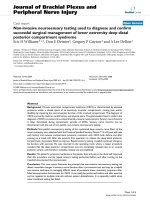
Figure 2-1: Illustration of skin flap harvest at a donor site; pedicle flap is shown with
vascular network. (Picture taken from Strauch et al, 1992)
2.2.1. Skin flap composition
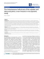
Skin flap comprises three main layers (Danielson, 1973), namely the epidermis,
dermis, and subcutaneous (fat). The latter two layers contain a network of blood
vessels (refer to Figure 2-2). The epidermis, which is a thin layer of stratified
epithelium, is the outer layer of skin, and the thickness varies according to location. It
7
Chapter 2 - Literature Review
is the thinnest on the eyelids at 0.05 mm and the thickest on the palms and soles at 1.5
mm (Fawcett, 1986). The dermis is composed mainly of collagen fibres, ground
substance and elastic fibres, and the dermis thickness also depends on location; it is
roughly 0.3 mm on the eyelids to 3 mm on the back. The fat layer is generally much
thicker than the dermal layer (Agache et al, 2004), and the thickness depends on the
Body Mass Index of the subject. The entire flap sits above the muscle surface,
separated by a thin tissue layer called fascia. At regions such as the scalp, the back of
the neck, the palms of the hands and sole of the feet, the skin flap is firmly anchored
to the underlying muscle tissues. At most other locations on the body, such as the
dorsal and volar regions, the skin flap may move freely over the muscle.
Figure 2-2: Cross section of human skin (Danielson, 1973)
2.2.2. Skin flap shrinkage
When a skin flap is harvested, m
ost of the time the flap shrinks and the resultant
wound (also call the secondary defect) expands. As early as 1950, Blocker and
Mithoefer advised that the flap should be cut one quarter to one third longer than the
defect so that it could be sutured in place in its relaxed retracted state (Blocker et al,
1950). It quickly became apparent to surgeons that the amount of excess tissue to be
harvested cannot be simplified as what was suggested by Blocker and Mithoefer.
8