Effect of temperature and trace water on surface forces studied by liquid AFM
Bạn đang xem bản rút gọn của tài liệu. Xem và tải ngay bản đầy đủ của tài liệu tại đây (4.64 MB, 209 trang )
EFFECT OF TEMPERATURE AND TRACE WATER ON
SURFACE FORCES STUDIED BY LIQUID AFM
LEONARD LIM TZE WEI
(B.Sc. (Hons.), National University of Singapore)
A THESIS SUBMITTED
FOR THE DEGREE OF DOCTOR OF PHILOSOPHY
DEPARTMENT OF PHYSICS
NATIONAL UNIVERSITY OF SINGAPORE
2008
i
Acknowledgements
To those who have worked in the Biosensor Lab #05-02 and Interfaces Lab #02-02
(IMRE). Thank you for your friendship and help throughout my years in IMRE,
especially Dr Cedric Troadec, Dr Aaron Lau, and Mr Tan Yee Yuan for their countless
hours of discussions and Dr Roderick Lim for his invaluable lessons on the fine art of
AFMing.
To the Cashewians, thank you for your friendship and advice, especially Boss, Kathy,
Kenny and Setha.
I am eternally grateful to my parents and mother-in-law for their support and patience
throughout the course of my studentship. To Siddy, thank you for helping me out in the
sticky situations all these years. To Jessica Koh, thank you for all the support and help in
getting me to keep my focus.
To the 1SAPians, thank you for your understanding and support, especially Glenn, CP,
Michiel, Victor and Karen.
I would like to express my deepest gratitude to Professor Andrew Wee for his great
support and advice throughout my candidature both experimentally and administratively.
Last but not least, to the “old man”, Dr Sean O’Shea for his stewardship, patience and
generosity. The experiences and lessons learnt have been invaluable. The discussions
about science and life in general have taught me much about what this world is all about.
ii
Table of Contents
Acknowledgements i
Table of Contents ii
Summary v
List of Figures vi
List of Tables xii
List of Publications xiii
Chapter One: Introduction 1
1.1 Motivation 1
1.2 Thesis Outline 5
Chapter Two: Literature Survey 6
2.1 Solvation Forces 6
2.2 Surface Force Apparatus Measurements 9
2.3 Atomic Force Microscopy Measurements 17
2.4 Computer Simulations 24
2.5 Concluding Remarks 26
Chapter Three: Experimental Methods 28
3.1 AFM Techniques 28
3.1.1 Cantilever Characterization 31
3.1.2 Tip Modification 36
3.1.3 Tip Characterization 40
3.1.4 Piezo Calibration 41
3.1.5 Force Measurements 42
iii
3.1.6 Conduction AFM 46
3.1.7 Temperature Control 47
3.2 STM Imaging 49
3.2.1 STM Tip Preparation 49
3.3 Materials 50
3.3.1 Liquids 50
3.3.2 Substrate 52
3.4 Miscellaneous Techniques 53
3.4.1 Trace Water Measurement 54
Chapter Four: Effects of Temperature and Tip Radius 56
4.1 Introduction 56
4.2 Experimental 58
4.2.1 General Force Curves 59
4.2.2 Important caveats regarding the force curve data 65
4.2.2.1 Inherent variability of data 66
4.2.2.2 Influence of Tip Size 69
4.2.2.3 The relevant forces to consider. 76
4.2.2.4 General conclusions regarding the quality of data 81
4.3 Experimental Force Curves at Different Temperatures 82
4.4 Discussion: Physical Basis of Temperature Dependent Observations 97
4.4.1 Large Temperature Change is not due to Density 98
4.4.2 Monolayer melting 99
4.4.3 Squeeze Out of the Confined Liquid : The Preferred Mechanism 105
4.5 Analytical Model of Temperature Dependent Squeeze Out 111
4.5.1 Analytical Model 113
4.5.2 Model results 120
iv
4.6 Conclusion 126
Chapter Five: Effects of Water 130
5.1 Preparation of Liquids 130
5.2 Solvation Forces Measured in Liquids with Water 133
5.2.1 OMCTS with Water 133
5.2.2 Hexadecane and Hexadecane with Water 135
5.2.3 Dodecanol with Water 136
5.3 STM Imaging & NMR 138
5.4 Discussion I 141
5.5 Adhesion Force in Other Alcohols 145
5.6 True Tip-HOPG Contact 147
5.7 Variation of Adhesion with Tip Material 149
5.7.1 Si Cantilevers 149
5.7.2 Au Coated Cantilevers 151
5.7.3 Al Coated Cantilevers 152
5.8 Drying Experiments 154
5.8.1 Boiling 154
5.8.2 Molecular Sieve 156
5.8.3 Freeze-thaw Method 157
5.8.4 Chemical Method – Sodium Sulphate 158
5.9 Discussion of Repulsive Adhesion Force 158
5.10 Conclusion 166
Chapter Six: Conclusions and Outlook 169
Bibliography 172
Appendix A: Tables of temperature dependent data. A-1
v
Summary
Solvation forces in confined liquids have been studied using the Atomic Force
Microscope (AFM), principally the effect of temperature, tip shape and trace amounts of
water in the liquid.
The effect of temperature on solvation forces have been studied in the liquids OMCTS, n-
hexadecane, and n-dodecanol. Discrete solvation layers can be observed for all three
liquids at all the temperatures measured (298K to 348K). However, with increasing
temperature there is a significant decrease in the magnitude of the measured solvation
forces and a reduction in the number of solvation oscillations which can be observed.
The normalized solvation force data, F/R
tip
, has also been found to differ between AFM
tips of different radius of curvature (R
tip
= 15nm to 100nm) with a clear trend of
decreasing F/R
tip
with increasing R
tip
.
The effect of trace water, with the exception of the OMCTS-HOPG system where the
data is inconclusive and no comment can be made, has been found to cause a decrease in
the magnitude of the maximum force (F
max
) for each layer, a decrease in the number of
observable jumps, and a decrease in the exponential decay length in the liquids n-
hexadecane and n-dodecanol.
vi
List of Figures
Figure 1.1 Schematic of the structure of a simple liquid confined between two
parallel walls. Taken from Ref. [1].
2
Figure 2.1 Typical force interaction curves of DLVO theory. Taken from Ref.
[1]
7
Figure 2.2 Schematic of a SFA for use in liquids. Taken from Ref. [1]. 10
Figure 2.3 Experimental results of force F as a function of separation D
between two curved mica surfaces of radius R = 1 cm separated by OMCTS at
22°C. Taken from Ref. [2]
12
Figure 2.4 Oscillatory solvation force superimposed on a monotonic force.
Taken from Ref. [1]
15
Figure 2.5 Principle of STM. Taken from Ref. [3] 18
Figure 2.6 Principle of a basic AFM. Taken from Ref. [3] 19
Fig 3.1. Simple schematic of AFM operation 28
Figure 3.2 (a) Homebuilt vacuum chamber for measurement of the fundamental
resonance frequency of a cantilever. (b) Typical plot of the measurement taken,
with the resonance frequency at 15.41 kHz.
34
Figure 3.3 Experimental setup for attaching beads 37
Figure 3.4 Graphic description of the bead attachment process. (a) A small
quantity of adhesive is applied onto a silicon substrate and the tip brought up
close to it. This picture is taken at x100 magnification. (b) Magnification is
changed to x500 and the tip is brought closer to the adhesive. (c) x500. The tip
is partially submerged into the adhesive. (d) The substrate with the adhesive is
removed and replaced by one with silica spheres dispersed on them. A single
sphere is chosen visually and the tip is brought up close to the sphere. (e) x500.
The tip is brought in contact with the sphere. (f) x500. The tip is then
withdrawn from the Si substrate and the bead is now mounted on the tip. (g)
SEM image of the tip apex mounted with the bead. Scale bar = 1µm.
39
Figure 3.5. SEM image of an AFM tip (a) Overall image of tip and cantilever.
(b) Zoomed in image of the tip.
40
vii
Figure 3.6 Schematic of how I
PSD
vs. Z (position sensitive detector current
signal vs. piezo position) are converted to force vs. distance curves for (a) a
simple “ideal” force curve (infinitely hard tip and sample without surface
forces) (b) Infinitely hard materials with long-range repulsion (c) Deformable
materials without surface forces (d) deformable materials with attraction and
adhesion force. Taken from Ref. [4]
42
Figure 3.7 (a) Typical raw data curve and (b) its corresponding converted
force-tip sample distance curve.
44
Figure 3.8 Conduction AFM setup. 47
Figure 3.9 Graphical plot of the setpoint temperature (Red ▲), substrate
temperature (Purple *) and liquid temperature (Hexadecane – Blue ■, OMCTS
– Yellow ♦, Dodecanol – Green ●).
48
Figure 3.10 Schematic of the molecular structure of the various liquids used. 51
Figure 3.11 4 x 4 nm STM image of HOPG. 53
Figure 4.1 Typical force curves near the HOPG surface for (a) OMCTS with
R
tip
= 40nm, (b) n-dodecanol with R
tip
= 25nm, and (c) n-dodecanol with R
tip
=
100 nm. The black curve (∆) is for tip approach and the red circles (○) for tip
retract. The tip-sample distance D=0 corresponds to the tip in mechanical
contact with the HOPG. The label n=1 shows the first solvation layer, n=2 the
second layer, etc. The force F
1
is the peak-peak force (maximum force minus
minimum force) in the n=1 layer.
61
Figure 4.2 Two examples of SEM images of a Si
3
N
4
tip after use. 63
Figure 4.3 Comparison of AFM solvation data for different tip radii in
hexadecane. The graphs show the same data as in the associated Table. The
“ratio” in the Table shows F
n
/R
tip
for n=1 divided by F
n
/R
tip
for n=2.
72
Figure 4.4 Comparison of AFM solvation data for different tip radii in
Dodecanol. The graphs show the same data as in the associated Table. The
“ratio” in the Table shows F
n
/R
tip
for n=1 divided by F
n
/R
tip
for n=2.
73
Figure 4.5 Generalized schematic of a spherical tip in contact with a flat
substrate (heavy solid lines). The pressure distribution comprises a repulsive,
Hertzian contribution (P
1
) and an adhesive part (P
2
). The net pressure (dashed
line) has tension components around the contact periphery and maximum at the
tip apex.
77
viii
Figure 4.6 Contact radius as a function of force for the Hertz, DMT and JKR
models of an elastic sphere-flat contact. F
ads
is fixed at -1.5 nN. To create this
plot the value of (3R
tip
/4K) is set to 10
-18
m
3
N
-1
, which is the typical order for
AFM experiments.
78
Figure 4.7 Force curves (approach is black, retract is red) near a HOPG surface
immersed in hexadecane taken at a) 25ºC, b) 45ºC and c) 75ºC with R
tip
= 45
nm. The tip-sample distance D=0Å corresponds to the tip in contact with the
HOPG.
82
Figure 4.8 Force curves (approach is black, retract is red) near a HOPG surface
immersed in dodecanol taken at a) 25ºC, b) 45ºC and c) 75ºC with R
tip
= 29 nm.
The tip-sample distance D=0Å corresponds to the tip in contact with the HOPG.
84
Figure 4.9 Force curves (approach is black, retract is red) near a HOPG surface
immersed in OMCTS taken at a) 25ºC, b) 45ºC and c) 55ºC with R
tip
= 40 nm.
The tip-sample distance D=0Å corresponds to the tip in contact with the HOPG.
85
Figure 4.10 Temperature dependence of the normalized peak-peak solvation
force for OMCTS near a HOPG surface for the a) n=1 and b) n=2 layers. Data
is only presented for the smallest radius tips used (R = 20nm, R = 40nm). There
is a small but clear decrease in F
n
/R with increasing temperature. The errors are
large in a relative sense because of the difficulty in measuring the very small
forces involved with OMCTS layers.
87
Figure 4.11 Temperature dependence of the normalized maximum solvation
force for hexadecane near a HOPG surface for the a) n=1 and b) n=2 layers.
There is a clear decrease in F
max
/R with increasing temperature. Data is only
presented for the smallest radius tips used (R = 15nm, R = 30nm). Data was
also taken for the n=3 layer but the forces are very small and only a qualitative
statement can be made that F
max
decreases with increasing temperature.
88
Figure 4.12 Temperature dependence of the maximum solvation force F
max
in
hexadecane near HOPG. The F
max
/R data for different tip radius (R
tip
= 15, 30,
36, 45, 50, 52, 55, 80 nm) is normalized to the corresponding value of F
max
/R at
25
o
C. A clear decrease in F
max
/R with increasing temperature is observed for all
tips. The n=2 data falls slightly more rapidly than the n=1 data.
89
Figure 4.13 a) Temperature dependence of the peak-peak solvation force for
dodecanol near a HOPG surface for the n=1 layer. Data is only presented for
the smallest radius tips used (R = 20nm to 29nm). b) Two data sets from (a) re-
plotted to give an indication of the errors involved. The R=23nm data is offset
by 1
o
C to for clarity. These large errors are typical.
91
Figure 4.14 Temperature dependence of the maximum solvation force and
corresponding adhesion force for dodecanol near a HOPG surface for the n=1
layer. The dashed line separates the two data sets. This data is used to find the
peak-peak values of Figure 4.13. Some of the data sets were offset by 1
o
C to
make the data easier to visualize.
92
ix
Figure 4.15 a) Temperature dependence of the peak-peak solvation force for
dodecanol near a HOPG surface for the n=2 layer. Data is only presented for
the smallest radius tips used (R = 20nm to 29nm). Some errors are shown to
give an idea of the magnitudes involved. b) Temperature dependence of the
maximum solvation force and corresponding adhesion force. The dashed line
separates the two data sets. This data is used to find the peak-peak values of (a).
Some of the data sets were offset by 1
o
C to make the data easier to visualize.
93
Figure 4.16 a) Temperature dependence of the peak-peak solvation force for
dodecanol near a HOPG surface for the n=3 layer. Data is only presented for
the smallest radius tips used (R = 20nm to 29nm). Some errors are shown to
give an idea of the magnitudes involved. b) Temperature dependence of the
maximum solvation force and corresponding adhesion force. The dashed line
separates the two data sets. This data is used to find the peak-peak values of (a).
Some of the data sets were offset by 1
o
C to make the data easier to visualize.
94
Figure 4.17 a) Temperature dependence of the peak-peak solvation force for
dodecanol near a HOPG surface for the n=1 layer. Data taken in 2005 using
larger radius tips (R = 40nm). b) Temperature dependence of the maximum
solvation force and corresponding adhesion force. The dashed line separates
the two data sets. This data is used to find the peak-peak values of (a). The
R=42.5nm data set is offset by 1
o
C for clarity.
96
Figure 4.18 a) STM image of the dodecanol monolayer (n=1) on HOPG.
Image size 15nm x 15nm. STM image conditions 20pA, 0.5V. b) AFM image
the hexadecane monolayer on HOPG. Image size 15nm x 15nm.[5]
100
Figure 4.19 Temperature dependence of the peak-peak solvation force F
n
in a)
OMCTS (n=1,2), and b) dodecanol (n=1,2,3). The F
n
/R data for different tip
radius is normalized to the corresponding value of F
n
/R at 25
o
C (R
tip
= 20 and
40nm for OMCTS; Rtip = 20, 20, 23, 25, 25, 29, 40, 42.5nm for dodecanol).
The “n=1 yr 2005” is a data set taken with dodecanol from a different bottle.
The circled data is from 1 single tip (R
tip
=20nm) which shows atypical behavior.
102
Figure 4.20 Simulation results at two temperatures of the average pressure
between two blocks with Xenon confined in between[6]. The two blocks move
towards each other starting at distance d=0 where ~4 Xe monolayers are
confined. The discontinuities show sudden removal of a lubrication layer. In
this simulation the lubricant layers are not strongly pinned to the substrate, a
situation similar to our experiments using a HOPG surface.
107
Figure 4.21 Simulated results of the pressure required to squeeze out the last
layer of confined butane and iso-butane as a function of temperature [207]. The
results at low temperature (<280K) have large errors because the simulation
becomes increasingly difficult. Note the approach velocity is 0.03 m/s, about 6
orders higher than a typical AFM experiment.
109
x
Figure 4.22 Schematic diagram showing the effect of an applied force on the
interaction potential. The dashed lines show the original potential well (width
x
β
, depth E
o
) and the linear loading potential. The applied force tilts the
combined potential (solid line) and lowers the activation barrier. Taken from
Ref. [7].
115
Figure 4.23 The rupture force F
n
calculated for different values of x
β
and E
0
(E
is in units of k
B
T as shown) at T=25
o
C. The force is calculated from F
n
=E
0
/x
β
because the logarithmic term in Equation 4.12 is negligible (see text for details).
The hatched regions show the range of the rupture force for the n=1 layer in
hexadecane (red) and OMCTS (green). The parameters x
β
and E
0
must lie
within these regions to correctly describe the data. Hence we conclude that x
β
<2nm and E
0
≥ 100k
B
T.
124
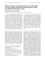
Figure 5.1 Solubility of water in normal alkanes at room temperature (298.15K) 132
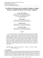
Figure 5.2 a) Force Distance curve for pure OMCTS. F
adh
=-1nN b) Force
Distance Curve for OMCTS with water. F
adh
=-0.35nN. Black shows the
approach curve and red the retraction curve.
134
Figure 5.3. a) Force Distance curve for pure Hexadecane. Water content ~
0.026% ppm. F
adh
=-1.2nN b) Force Distance Curve for Hexadecane with water
(~ 0.030% ppm). F
adh
=+0.5nN. Black shows the approach curve and red the
retraction curve.
136
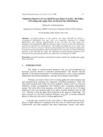
Figure 5.4 a) Force Distance curve for pure Dodecanol. Water content ~
0.022% ppm. F
adh
=+1.8nN b) Force Distance Curve for Dodecanol with water
(~ 0.061%). F
adh
=+0.35nN. Note the “positive” adhesion forces. Black shows
the approach curve and red the retraction curve.
137
Figure 5.5 (a) STM image of dodecanol monolayer (0% water added) on HOPG
(15 nm x 15 nm), (b) dodecanol monolayer with water (~ 0.061% ppm) (20 nm
x 20 nm) and (c) dodecanol monolayer with water (~ 0.061% ppm) (10 nm x 10
nm)
139
Figure 5.6 c-NMR results for a) Hexadecane, and b) Hexadecane with 0.005%
ppm water added. Inset shows a Hexadecane skeleton diagram with the
corresponding c-NMR peak numbers.
140
Figure 5.7 h-NMR results for a) Hexadecane, and b) Hexadecane with 0.005%
ppm water added. Inset shows a Hexadecane skeleton diagram with the
corresponding h-NMR peak numbers.
141
Figure 5.8 Typical force curve measured in the Si
3
N
4
-Octanol-HOPG system.
R
tip
= 35nm.
146
Figure 5.9 Typical force curve measured in the Si
3
N
4
-Ethanol-HOPG system.
R
tip
= 24nm.
147
xi
Figure 5.10 AFM scan of HOPG surface taken in dodecanol at a force of
~10nN. Si
3
N
4
cantilever (k
c
= 0.76 N/m)
148
Figure 5.11 Typical results for the a) Si-FM levers and b) Si-NCAFM levers 150
Figure 5.12 Typical force curve for a Au coated Si
3
N
4
cantilever in dodecanol.
R
tip
= 55nm.
151
Figure 5.13 Thickness of aluminum oxide growth as a function of oxygen
exposure. Taken from Ref. [8]
152
Figure 5.14 Distribution of the observation of positive adhesion with respect to
tip radius for an Al coated tip. The blue triangles ▲ represent the beginning of
the experiment and the pink squares ■ when the experiment is repeated after 24
hours. The Al tip was exposed to ambient during the 24 hour period.
153
Figure 5.15 FTIR plot for dodecanol as purchased (dark blue) and boiled for 24
hours (light blue).
155
Figure 5.16 The normalized force F/R measured between SiO
2
surfaces
immersed in aqueous solutions. Taken from Ref. [9].
161
Figure 5.17 ADXPS-derived data from Ref. [10]. 164
xii
List of Tables
Table 3.1. Typical dimensions and properties of cantilevers used in this work 33
Table 4.1 A summary from a typical experiment. Each row summarizes a single force
curve. The subscripts n=1, 2, and 3 represent the first, second and third solvation layers
respectively. Shown is the maximum force to push through a solvation layer (F
max
), the
various adhesion minima (F
adh
), and the maximum force minus the adhesive minima
(F
n
).
66
Table 4.2 Comparison of the solvation data for OMCTS taken with surfaces of different
radii of curvature.
71
Table 4.3 Density and melting temperature at atmospheric pressure of the three liquids
used. The liquids hexadecane and dodecanol are known to form ordered adsorption
layers near a HOPG surface and these layers melt at temperatures considerably higher
than the bulk, typically ~10% higher for the monolayer. The melting temperatures of
molecular layers can be measured using differential scanning calorimetry and
representative data from the literature is shown for hexadecane and dodecanol.
99
Table 4.4 The order of magnitude for the entropy (∆S), enthalpy (∆H) and energy (E
0
)
of rupture of the n=1 and n=2 solvation layers in hexadecane, dodecanol and OMCTS.
The slope dFn/dT and rupture forces Fn (at 25
o
C) are taken from Figures 4.10, 4.11,
4.13 and 4.15. The energy terms are crudely calculated from ∆S = x
β
.dFn/dT, ∆H = E
0
+ T∆S, and E0 = Fnx
β
using the load rate r=5nN/s and x
β
= 0.5nm. The assumption that
x
β
is constant for all the systems and solvation layers are very weak and values of x
β
should be obtained experimentally [11]. Another significant unknown is the number of
interacting bonds or molecules (N) contributing to the overall energy values noted in the
Table.
122
Table 5.1 Tabulation of amount of water in samples. The 5% values are measured
using a Mettler Toledo DL32. All other values are obtained using an AlphaTitroline.
The (*) values are calculated from the measured volume. Note that 0% added water
refers to the as received samples.
131
Table 5.2 Constants used for calculation of the non-retarded Hamaker constant. 144
Table 5.3 Dielectric Permittivities, Refractive Indices and Hamaker constant of a Si
3
N
4
tip interacting with HOPG across liquid alcohols of various chain lengths from
reference [12].
145
Table 5.4 Summary of effects of tip coating on the adhesion force in dodecanol 159
Table 5.5 Tabulation of the % of force curves showing positive adhesion for ethanol
added to Hexadecane. Two Si
3
N
4
tips (k
c
= 0.38 N/m) were used.
163
xiii
List of Publications
Refereed Journals
1. Temperature dependence of solvation forces as measured in atomic force
microscopy
Lim, L.T.W., A.T.S. Wee, S.J. O’Shea
The Journal of Chemical Physics, 2009 130(13)
2.
Effect of Tip Size on Force Measurement in Atomic Force Microscopy.
Lim, L.T.W., A.T.S. Wee, and S.J. O'Shea
Langmuir, 2008. 24(6): p. 2271-2273.
3. Fabrication and Characterization of Multilayer Amorphous Carbon
Films for Microcantilever Devices
E.H.T. Teo, D.H.C. Chua, L.T.W. Lim, S. O’Shea, J.M. Miao, and B.K. Tak
IEEE Sensors Journal, 2008, 8(5): p. 616-620
4. Vibratory Response of Diamond-Like Amorphous Carbon Cantilevers
under Different Temperatures
Chua, D.H.C., B.K. Tay, P. Zhang, E.H.T. Teo, L.T.W. Lim, S. O’Shea, J. Miao
Diamond and Related Materials, 2004 13(11-12): p. 1980-1983
Manuscripts in Preparation
5. Effect of Water on Force Measurement in Atomic Force Microscopy
Lim, L.T.W., A.T.S. Wee, S.J. O’Shea
Langmuir (Manuscript in Preparation)
Chapter One - Introduction
1
Chapter One: Introduction
1.1 Motivation
Understanding of force interactions between two surfaces is of immense importance from
the fundamental viewpoint of confined materials and practical applications in lubrication,
adhesion, tribology, coatings and the interactions between colloidal particles[1]. The
study of the solid-liquid interface has been greatly accelerated over the last quarter of a
century by the development of the Surface Force Apparatus (SFA) in 1969[13], Scanning
Tunneling Microscopy (STM) in 1981[14, 15] and Atomic Force Microscopy (AFM) in
1986[16]. Until then, the study of the atomic structure at the solid-liquid interface had
been dominated by methods such as modeling, X-ray diffraction, and electron diffraction.
With the aid of SFA, STM and AFM results, together with detailed computer simulations,
it is now generally understood that the properties of a liquid close to a surface can be
quite different from that in the bulk.
An interesting aspect of the solid-liquid interface is the induced molecular ordering in
liquids between two solid surfaces immersed in a liquid. Oscillatory type forces (also
termed solvation forces) can arise from the variation of the liquid molecular density
between the surfaces[1] primarily due to geometric packing reasons (see Figure 1.1). As
the two surfaces are brought together, the liquids between them may pack, becoming
more “solid-like”, at separations which are multiples of the molecular diameter of the
liquid.
Chapter One - Introduction
2
Figure 1.1 Schematic of the structure of a simple liquid confined between two parallel walls. From Ref.
[1].
Much of the early work in solvation forces were performed using a SFA and a wide range
of experiments have been conducted since the first reported observation of oscillatory
solvation forces by Horn and Israelachvili [17] in 1980. Numerous experiments
involving a variety of surfaces[1, 18-20], aqueous and non-aqueous liquid
combinations[21-28] were conducted by Israelachvili and co-workers in the years
following, and from these experiments, they arrived at the conclusion that oscillatory
solvation forces[1, 29] were strongly affected by (Issue 1) molecule rigidity, (Issue 2)
molecule structure, (Issue 3) surface roughness, and (Issue 4) trace water content, but not
strongly influenced by temperature (Issue 5).
With the development of the AFM in 1986, it was inevitable similar solvation force
measurements would be carried out using this new tool. Pioneering work by O’Shea et
al.[30] in 1992 revealed the presence of solvation forces even at the nanometer length
Chapter One - Introduction
3
scales. Since then, solvation forces involving different liquids and substrates have been
studied using AFM [31-37].
Previous AFM work has highlighted the narrowness of the generalizations regarding
oscillatory solvation forces noted above as Issues 1-5 (See also Section 2.2). For
example, in contrast to SFA experiments, it has been shown using AFM that branched
molecules can exhibit strong solvation layering [35] (Issue 2) and solvation forces can
still be observed on nominally rough surfaces [37] (Issue 3) because the AFM tip is of the
same length scale as the roughness (macroscopically rough surfaces in SFA experiments
will “average out” oscillatory force behavior).
Thus conclusions derived from SFA experiments may not necessarily be applicable to
AFM measurements chiefly because of the small contact area of AFM compared to
SFA[38]. The interacting area in AFM is ~ 10
6
times smaller than those in SFA, and
some of the experimental consequences (among many) are; i) The viscous force on a
spherical particle scales with the square of the particle radius resulting in AFM
measurements at speeds 10
4
times greater than SFA while maintaining the same viscous
force to surface force ratio.[39] ii) The AFM is less susceptible to contamination given
the smaller interacting surfaces.[39]
In this Thesis we use AFM to gain further fundamental understanding of oscillatory
solvation forces. Specifically, we measure the oscillatory forces between a graphite
surface and an AFM tip in the presence of simple organic liquids (hexadecane, dodecanol
and octamethylcyclotetrasiloxane) and study the effect of temperature (Issue 5 above), tip
shape and trace amounts of water in the liquid (Issue 4 above).
Chapter One - Introduction
4
In contrast to SFA experiments we find that temperature dramatically changes the
measured solvation forces in AFM. The solvation forces themselves are not strongly
temperature dependent but the small length scale in AFM introduces another mechanism
into the measurement related to how the liquid squeezes out of the tip-sample gap when
pressure is applied. The squeeze out process is thermally activated and gives rise to an
approximately linear dependence of force with temperature. This fundamentally kinetic
approach is a different way of viewing AFM measurements of solvation forces, with
strong implications on how temperature influences boundary lubrication films.
There is also a strong influence arising from the presence of trace water on the measured
solvation forces. (It should be noted that the experiments use trace amounts of water
(~100ppm) as distinct from many studies dealing with aqueous solutions or mixtures.)
The solvation layers are disrupted and the magnitude and range of the oscillatory force
decreases. A very interesting observation was that of “positive” adhesion using certain
combinations of liquids and tip material. Positive adhesion refers to the phenomena that
when a tip was in contact with the graphite surface and then withdrawn, the adhesion
force was repulsive. This contrasts to the negative, van der Waals adhesion typically
measured. This phenomena was thoroughly studied (albeit qualitatively) and we
hypothesize that on oxide covered AFM tips trace amounts of water can hydrate because
of the surface hydroxyl groups, giving rise to a repulsive hydration force [1].
The work on the influence of tip size stemmed from the observation that the magnitude of
the solvation forces did not scale with the radius of the tip as expected, but became
smaller. This is due to an increase in the local roughness, leading to an “averaging out”
Chapter One - Introduction
5
of the measured oscillatory force. We concluded that to avoid a systematic error in the
force measurements, and hence in the measurement of the interaction energy between
two surfaces, one should always use the tips of the smallest radius of curvature.
1.2 Thesis Outline
A literature survey of both theoretical and experimental aspects of solvation forces is
given in Chapter 2. This is followed by a description of the experimental methods and
materials used in this work. Chapter 4 covers the experimental results attained for our
study of the temperature dependence of solvation forces and tip shape effects. Chapter 5
presents the experimental results obtained for work done to explore the effects of trace
amounts of water on solvation forces. Finally, a summary of the research is presented in
Chapter 6 together with suggestions of future work.
Chapter Two – Literature Survey
6
Chapter Two: Literature Survey
2.1 Solvation Forces
Oscillatory forces at interfaces were first predicted in 1912 by W.B. Hardy[40]. His
concept of the surface zone of a liquid, where the surface monomolecular layer affected
the orientation and properties of the overlying liquid for a few molecular layers,
contradicted the classical belief that the surface zone is unaltered bulk liquid[41]. In the
years following, further experimental work continued to suggest that solvent structures
played a major role in particle interactions. One example was the x-ray diffraction
experiments by B.E. Warren[42] which showed that elongated liquid molecules and their
immediate neighbors mostly lie side by side. However, the question persisted of how
large a role the surface or an oriented monolayer of the molecule played. Even the extent
to which solvation forces occur and manifestation of their existence was in question.
In a review paper by J.C. Henniker[41] in 1949, evidence from earlier work on the
existence of surface orientation was compiled. Direct evidence (data appearing to
constitute definite proof) was said to come mainly from x-ray and electron diffraction
work but compelling results from refractive index, surface viscosity, and adhesion were
also added. Other, more circumstantial evidence came from studies of soap films, flow in
narrow passages, rigidity of water layers, viscosity of organic liquids through clay, and
density of a water layer on the surface of platinum. The evidence from the data reviewed
showed that physical constants of the surface region may differ from those of the bulk
and that molecular orientation to a certain depth from the surface was observable.
Chapter Two – Literature Survey
7
At about the same time, seminal research by Henniker, Derjaguin, Landau, Verwey and
Overbeek developed a theory to explain the aggregation of aqueous dispersions[43-45].
In this theory, called the DLVO theory, the coagulation of dispersed particles is explained
by the interplay between two forces: the attractive van der Waals force and the repulsive
electrostatic double-layer force.
Figure 2.1 Typical force interaction curves of DLVO theory. Taken from Ref. [1]
The van der Waals force, which is described by the Lifshitz theory[46, 47] and is
attractive, is responsible for the coagulation whereas the stability of the dispersion is the
work of the repulsive electrostatic double-layer force (Figure 2.1). For large separations,
Chapter Two – Literature Survey
8
the continuum theories of van der Waals and the electrostatic double-layer are a good
description of the interaction between two surfaces. However for small separations,
closer than 10nm for colloids, unexpected large repulsions often appeared in contrast to
the DLVO theory which predicts that ultimately an attraction must appear, irrespective of
the medium in the gap. This failure of the DLVO theory has been attributed to additional
short range contributions to the force, mainly the hydration force in aqueous media and
the more general structural or solvation force. In this Thesis we are mainly concerned
with solvation force, although the hydration force is also important when water is present
in our experiments (see Chapter 5).
Hints about the exact nature of the structural or solvation force first came from
simulations and theory [48-57] which showed the constraining effect of two solid
surfaces can dramatically affect the confined liquid. When two surfaces are brought
towards each other at very small separations (nanometer length scales), individual layers
of molecules are squeezed out of the closing gap. The variation of the liquid density
profile between two walls was found to give rise to a decaying oscillatory force acting on
the walls of a magnitude comparable to the van der Waals interaction [52, 55, 57-59]. As
these forces are results of the “adsorption” of solvent molecules to solid surfaces, they
were termed solvation forces[52]. The main conclusion drawn from the work was that
density fluctuations cause an exponential decay of the oscillatory force, with the
periodicity of the force corresponding approximately to the thickness of each molecular
layer (See Figure 1.1). The density profile was also found to be affected by the
interactions between the fluid molecules and the walls[48, 60] and this affects the
Chapter Two – Literature Survey
9
packing density near the walls[48]. In general, the variation of the solvation force with
wall separation may be oscillatory, monotonic or both.
Although there were many theoretical studies devoted to solvation forces, the first
experimental evidence proof was elusive and came only in 1980 using the Surface Force
Apparatus[17].
2.2 Surface Force Apparatus Measurements
The Surface Force Apparatus (SFA) was developed in 1969 by Tabor and Wintertorn[13]
as a method to measure the forces in air between two cylindrical sheets of mica, placed at
90° to each other. One surface was held rigidly and the other on a light cantilever beam.
A multiple beam interferometer was used to determine the surface separation to an
accuracy of ±0.3nm. A measurement of the magnitude of the van der Waals forces could
be made for separations ranging from 5 to 30nm. This was repeated in 1972 by
Israelachvili and Tabor[61] and both sets of experiments confirmed the Lifshitz theory of
van der Waals forces. These experiments, however, were conducted in air.
Chapter Two – Literature Survey
10
Figure 2.2 Schematic of a SFA for use in liquids. Taken from Ref. [1].
The first SFA experiment in a liquid environment (see Figure 2.3) was reported in 1978
by Israelachvili and Adams[62] in aqueous electrolyte solutions. In their experiments,
van der Waals and double-layer forces were measured but there was an observation of an
additional repulsive force. At large separations (≥ 7.5nm), the measured forces were
close to that expected from the DLVO theory. At small separations the forces often
deviated drastically from theoretical expectations. Further work was done to measure
long-range forces between surfaces in polymer solution[63].
Chapter Two – Literature Survey
11
In 1980, the first results showing oscillatory (or solvation) forces was published[17],
using the liquid Octamethylcyclotetrasiloxane (OMCTS), [(CH
3
)
2
SiO]
4
(Figure 2.3).
Given its large size (molecular diameter ~ 1nm), nearly spherical molecular shape,
chemical inertness and low polarity[64], OMCTS is close to mimicking a Lennard-Jones
fluid. The following general features were concluded from the experiments[2]:
1. The decaying oscillatory forces were measurable up to about 10nm (ten molecular
diameters for OMCTS)
2. The first four or five oscillations were found to have a slightly reduced periodicity
as compared to the layers further out. This was attributed the reduced mobility of
the molecules on the surface, lying with their shorter axes perpendicular to the
surfaces. Another possibility was that the spheres closer to the surface packed
with higher efficiency as compared to those more than 5 layers from the surface.
3. The peak-to-peak amplitudes were found to decay roughly exponentially with
distance.
4. The oscillations do not appear to be sinusoidal closer to the surface but become
more sinusoidal as the separation distance increased.
Very similar results were obtained with cyclohexane[2] between mica surfaces and it was
found that the oscillation periodicity was 0.6±0.1nm, approximately the size of
cyclohexane molecules.