Blind channel identification equalization with applications in wireless communications
Bạn đang xem bản rút gọn của tài liệu. Xem và tải ngay bản đầy đủ của tài liệu tại đây (1.19 MB, 236 trang )
BLIND CHANNEL
IDENTIFICATION/EQUALIZATION
WITH APPLICATIONS IN WIRELESS
COMMUNICATIONS
JUN FANG
NATIONAL UNIVERSITY OF SINGAPORE
2006
BLIND CHANNEL IDENTIFICATION/EQUALIZATION
WITH APPLICATIONS IN WIRELESS
COMMUNICATIONS
JUN FANG
(B.Sc. and M.Sc., Xidian University, China)
A THESIS SUBMITTED
FOR THE DEGREE OF DOCTOR OF PHILOSOPHY
DEPARTMENT OF ELECTRICAL AND COMPUTER ENGINEERING
NATIONAL UNIVERSITY OF SINGAPORE
2006
Acknowledgment
First and foremost, I would like to express my sincere gratitude to my supervisor
Dr. A. Rahim Leyman, for his guidance, support and his liberal attitude to my
research. He demonstrated great freedom and patience on my research. This
enabled me to develop my own interests and enjoy the process of intellectual ex-
perience during the course of my research. Many thanks go to my co-supervisor
Dr. Chew Yong Huat for his helps and discussions on my research.
I also wish to thank all my colleagues and friends who have given me so much
helps and encouragements throughout these three years’ studies. I would like
to acknowledge the Institute for Infocomm Research and National University of
Singapore for their generous financial support and facilities. Besides, my work
was partially supported by the Singapore’s Agency for Science, Technology and
Research (A*STAR) under Research Grant Number 022-106-0041.
Finally, heartfelt thanks go to my beloved. I am deeply indebted to my parents
and my wife for their constant love and untiring support. It is them who
encourage and accompany me during the hardest days of my research.
i
Summary
The rapid growth in demand for cellular communications services has encour-
aged research into the design of wireless communications to improve spectrum
efficiency and link q uality. As opposed to their wireline counterpart, wire-
less communication systems pose some unique challenges. One of the main
problems faced in wireless communications is the intersymbol interference (ISI)
caused by channel dispersion and the multiuser interference (MUI) resulting
from frequency reuse. In order to recover the desired transmitted user sig-
nals accurately, advanced space-time signal processing techniques need to be
developed to simultaneously suppress the ISI and MUI. A key asp ect of these
is the estimation of the channel. Traditional methods for channel estimation
usually resort to training sequences to enable channel identification. These pe-
riodically transmitted training sequences consume considerable bandwidth and
thus reduce the bandwidth usage efficiency. Over the past decade, a promising
approach called as “blind method” has received significant attention. As com-
pared to the traditional techniques, blind channel estimation methods identify
the unknown wireless channels based only on the received signals and some a
priori statistical information or properties of the input signals, without direct
access to the transmitted signals.
This dissertation focuses on the blind estimation of the wireless channels by
ii
exploiting the statistical information of the received data. We have developed
a variety of statistics-based blind channel estimation methods for different data
models, i.e., single-input single-output (SISO), single-input multiple-output
(SIMO) and multiple-input multiple-output (MIMO) models. The proposed
algorithms can be directly applied or tailored to diverse wireless communica-
tion systems, such as TDMA and CDMA, to combat the ISI and MUI which
constitute a major impediment to the system performance. In this dissertation,
we, firstly, introduce the background, revie w, mathematical preliminaries and
basic models for blind channel identification. Next, in Chapter 3, we present a
higher order statistics-based linear method to estimate the SISO wireless chan-
nels. In Chapters 4 and 5, by utilizing the properties of the companion matrices,
a new second-order statistics-based method for blind estimation of SIMO and
MIMO channels driven by colored sources is proposed. In Chapter 6, we derive
a new metho d to directly estimate the zero-forcing (ZF) or minimum mean-
square-error (MMSE) equalizers of the SIMO channel driven by colored sources
with unknown statistics. We also studied the problem of blind identification
of MIMO channels driven by spatially correlated sources with a priori known
statistics. The results are presented in Chapter 7. Finally, in Chapter 8, we
conclude with a summary of contributions and directions for future research.
iii
Contents
Acknowledgement i
Summary ii
Abbreviations xiii
Notations xv
1 Introduction 1
1.1 Radio Propagation Model . . . . . . . . . . . . . . . . . . . . . . 2
1.1.1 Path Loss and Fading . . . . . . . . . . . . . . . . . . . . 2
1.1.2 Multipath . . . . . . . . . . . . . . . . . . . . . . . . . . . 5
1.1.3 Space-Time Channel Model . . . . . . . . . . . . . . . . . 8
1.2 Motivation for B lind Channel Estimation . . . . . . . . . . . . . 16
1.3 Review of Blind Channel Estimation Techniques . . . . . . . . . 18
1.4 Motivations and Contributions of the Thesis . . . . . . . . . . . . 30
1.5 Thesis Outline . . . . . . . . . . . . . . . . . . . . . . . . . . . . 35
2 Background – Mathematical Preliminaries 37
2.1 Moments and Cumulants . . . . . . . . . . . . . . . . . . . . . . 37
2.1.1 Definitions and Properties . . . . . . . . . . . . . . . . . . 38
2.1.2 Ergodicity and Moments . . . . . . . . . . . . . . . . . . . 41
iv
2.2 Data Model . . . . . . . . . . . . . . . . . . . . . . . . . . . . . . 43
3 Blind Estimation of SISO FIR Channel 49
3.1 Introduction . . . . . . . . . . . . . . . . . . . . . . . . . . . . . . 50
3.2 Preliminaries . . . . . . . . . . . . . . . . . . . . . . . . . . . . . 52
3.2.1 System Model . . . . . . . . . . . . . . . . . . . . . . . . . 52
3.2.2 Cumulant Matrices . . . . . . . . . . . . . . . . . . . . . . 53
3.3 Channel I dentification . . . . . . . . . . . . . . . . . . . . . . . . 54
3.3.1 Principle for Channel Identification . . . . . . . . . . . . . 54
3.3.2 Practical Analysis of Channel Identification . . . . . . . . 58
3.4 Algorithm De velopment . . . . . . . . . . . . . . . . . . . . . . . 61
3.5 Simulation Results . . . . . . . . . . . . . . . . . . . . . . . . . . 64
3.5.1 Example A . . . . . . . . . . . . . . . . . . . . . . . . . . 65
3.5.2 Example B . . . . . . . . . . . . . . . . . . . . . . . . . . 68
3.6 Summary . . . . . . . . . . . . . . . . . . . . . . . . . . . . . . . 70
4 Blind Identification of SIMO FIR Channel 71
4.1 Introduction . . . . . . . . . . . . . . . . . . . . . . . . . . . . . . 71
4.2 System Model and Basic Assumptions . . . . . . . . . . . . . . . 73
4.3 Proposed Channel Identification Method . . . . . . . . . . . . . . 74
4.4 Simulation Results . . . . . . . . . . . . . . . . . . . . . . . . . . 81
4.5 Summary . . . . . . . . . . . . . . . . . . . . . . . . . . . . . . . 83
5 Blind Identification of MIMO FIR Channel 84
5.1 Introduction . . . . . . . . . . . . . . . . . . . . . . . . . . . . . . 84
5.2 System Model and Basic Assumptions . . . . . . . . . . . . . . . 88
5.3 Proposed Channel Identification Method . . . . . . . . . . . . . . 89
v
5.3.1 Inherent Structural Relationship of Source Autocorrela-
tion Matrices . . . . . . . . . . . . . . . . . . . . . . . . . 92
5.3.2 Properties of Companion Matric es and The Identifiability
Conditions . . . . . . . . . . . . . . . . . . . . . . . . . . 94
5.3.3 Proof of The Solution Uniqueness and The Proposed Al-
gorithm . . . . . . . . . . . . . . . . . . . . . . . . . . . . 96
5.3.4 Joint Order Detection and Channel Estimation . . . . . . 99
5.3.5 Noise Compensation . . . . . . . . . . . . . . . . . . . . . 101
5.4 Discussions . . . . . . . . . . . . . . . . . . . . . . . . . . . . . . 102
5.4.1 Computational Complexity . . . . . . . . . . . . . . . . . 103
5.4.2 Channel Identifiability Condition . . . . . . . . . . . . . . 104
5.5 Simulation Results . . . . . . . . . . . . . . . . . . . . . . . . . . 105
5.5.1 Scenario with Multiple Sources – Channel Estimation . . 106
5.5.2 Scenario with Multiple Sources – Channel Equalization . 107
5.6 Summary . . . . . . . . . . . . . . . . . . . . . . . . . . . . . . . 116
6 Blind Equalization of SIMO FIR Channel 117
6.1 Introduction . . . . . . . . . . . . . . . . . . . . . . . . . . . . . . 117
6.2 System Model and Basic Assumptions . . . . . . . . . . . . . . . 120
6.3 Proposed Channel Equalization Method . . . . . . . . . . . . . . 122
6.3.1 Inherent Structural Relationship Between Source Auto-
correlation Matrice s . . . . . . . . . . . . . . . . . . . . . 123
6.3.2 Channel Equalization . . . . . . . . . . . . . . . . . . . . 124
6.3.3 Equalizability Condition and Relation with Other Work . 132
6.3.4 Channel Estimation . . . . . . . . . . . . . . . . . . . . . 135
6.3.5 Noise Compensation and MMSE Equalizers . . . . . . . . 136
6.3.6 Discussions . . . . . . . . . . . . . . . . . . . . . . . . . . 138
vi
6.4 Simulation Results . . . . . . . . . . . . . . . . . . . . . . . . . . 138
6.4.1 Example One . . . . . . . . . . . . . . . . . . . . . . . . . 139
6.4.2 Example Two . . . . . . . . . . . . . . . . . . . . . . . . . 141
6.5 Summary . . . . . . . . . . . . . . . . . . . . . . . . . . . . . . . 149
7 Further Studies on MIMO FIR Channel Identification 150
7.1 Introduction . . . . . . . . . . . . . . . . . . . . . . . . . . . . . . 151
7.2 System Model and Basic Assumptions . . . . . . . . . . . . . . . 153
7.3 Proposed Channel Identification Method for Spatially Correlated
Sources . . . . . . . . . . . . . . . . . . . . . . . . . . . . . . . . 154
7.3.1 Property of Triangular Matrix . . . . . . . . . . . . . . . 157
7.3.2 Proof of The Solution Uniqueness and The Proposed Al-
gorithm . . . . . . . . . . . . . . . . . . . . . . . . . . . . 158
7.3.3 Discussions . . . . . . . . . . . . . . . . . . . . . . . . . . 161
7.4 Channel Identifiability Condition for Spatially and Temporally
Uncorrelated Inputs . . . . . . . . . . . . . . . . . . . . . . . . . 163
7.5 Simulation Results . . . . . . . . . . . . . . . . . . . . . . . . . . 168
7.5.1 Example One . . . . . . . . . . . . . . . . . . . . . . . . . 169
7.5.2 Example Two . . . . . . . . . . . . . . . . . . . . . . . . . 170
7.5.3 Example Three . . . . . . . . . . . . . . . . . . . . . . . . 173
7.5.4 Example Four . . . . . . . . . . . . . . . . . . . . . . . . . 175
7.6 Summary . . . . . . . . . . . . . . . . . . . . . . . . . . . . . . . 178
8 Conclusions and Future Work 179
8.1 Conclusions . . . . . . . . . . . . . . . . . . . . . . . . . . . . . . 179
8.2 Future Work . . . . . . . . . . . . . . . . . . . . . . . . . . . . . 181
A Proof of Lemma 4.3 183
vii
B Proof of Lemma 5.3 186
C P roof of Theorem 5.2 193
D Proof of Lemma 7.1 195
E Proof of Lemma 7.2 197
F Proof of Theorem 7.3 200
Publications 201
Bibliography 203
viii
List of Figures
1.1 The fading phenomena (this figure is adopted from [2]) . . . . . 5
1.2 The propagation mechanisms . . . . . . . . . . . . . . . . . . . . 6
1.3 The multipath propagation . . . . . . . . . . . . . . . . . . . . . 10
1.4 Smearing of received signal by ISI . . . . . . . . . . . . . . . . . 14
1.5 Schematic of blind channel identification . . . . . . . . . . . . . . 19
1.6 Classification of blind channel estimation methods . . . . . . . . 23
2.1 Single-input multiple-output model . . . . . . . . . . . . . . . . . 43
2.2 Multiple-input multiple-output model . . . . . . . . . . . . . . . 45
3.1 NMSE of the channel estimate versus SNR under different num-
ber of samples used. . . . . . . . . . . . . . . . . . . . . . . . . . 67
3.2 NMSE of the channel estimate versus SNR with channel order
overestimated by 1 and 2 respectively . . . . . . . . . . . . . . . 69
3.3 NMSE of the channel estimate versus SNR. Solid lines are for
T
s
= 1600; dashed lines for T
s
= 800. . . . . . . . . . . . . . . . . 69
5.1 NRMSE of the estimated channel versus SNR, T
s
= 2000 . . . . 108
5.2 NRMSE of the estimated channel versus number of samples T
s
,
SNR = 30dB . . . . . . . . . . . . . . . . . . . . . . . . . . . . . 109
5.3 SER versus SNR, T
s
= 2000 . . . . . . . . . . . . . . . . . . . . . 112
ix
5.4 SER versus number of data samples T
s
, SNR = 19dB . . . . . . . 113
5.5 SER versus equalization delays, SNR = 19dB, T
s
= 2000 . . . . . 114
5.6 SER versus SNR for the ‘weakly’ satisfied spectral diversity con-
dition, T
s
= 2000 . . . . . . . . . . . . . . . . . . . . . . . . . . . 115
6.1 Example 1: SER versus SNR for the MMSE equalizers with dif-
ferent delays; T
s
= 1000. . . . . . . . . . . . . . . . . . . . . . . . 142
6.2 Example 1: SER of the MMSE equalizer with d
e
= 2 versus SNR
using different number of data samples. . . . . . . . . . . . . . . 142
6.3 Example 1: NRMSE of the estimated channel versus SNR using
different number of data samples. . . . . . . . . . . . . . . . . . . 143
6.4 Example 1: SER of the MMSE equalizers with best delays versus
SNR as the stack number varies from 3 to 7, T
s
= 1000. . . . . . 143
6.5 Example 1: SER of the respective algorithms versus SNR, d
e
= 2,
T
s
= 1000. . . . . . . . . . . . . . . . . . . . . . . . . . . . . . . . 144
6.6 Example 2: SER of the respective algorithms versus SNR, d
e
= 2,
T
s
= 800. . . . . . . . . . . . . . . . . . . . . . . . . . . . . . . . 146
6.7 Example 2: SER of the respective algorithms versus SNR using
different number of data samples, d
e
= 2, SNR = 15dB. . . . . . 146
6.8 Example 2: SER of the resp e ctive algorithms versus SNR, d
e
= 2. 147
6.9 Example 2: SER of the respective algorithms versus SNR, d
e
= 1,
T
s
= 400. . . . . . . . . . . . . . . . . . . . . . . . . . . . . . . . 148
7.1 Example 1: SER versus SNR for different equalization delays d
e
;
T
s
= 2000 . . . . . . . . . . . . . . . . . . . . . . . . . . . . . . . 171
7.2 Example 1: SER versus T
s
for different SNR; d
e
= 5 . . . . . . . 172
7.3 Example 2: Performance of respective algorithms . . . . . . . . . 174
7.4 Example 3: Performance of respective algorithms . . . . . . . . . 176
x
7.5 Example 4: Performance of the proposed algorithm . . . . . . . . 177
xi
List of Tables
3.1 SER versus SNR of the respective algorithms under different
number of data samples . . . . . . . . . . . . . . . . . . . . . . . 68
4.1 SER versus SNR and number of data samples respectively . . . . 82
6.1 Transition probabilities for Markov source . . . . . . . . . . . . . 144
6.2 Autocorrelation function of the Markov source . . . . . . . . . . 144
xii
Abbreviations
CCI Co-Channel Interference
CDMA Code Divi sion Multiple Access
FDMA Frequency Division Multiple Access
FIR Finite I mpulse Response
GSM Global System for Mobile Communications
HOS Higher Order Statistics
i.i.d. Independent and identically distributed
ISI Intersymbol Interference
IS-54 Interim Standard 54
LOS Line of Sight
MIMO Multiple I nput Multiple Output
ML Maximum Likelihood
MMSE Minimum Mean Square Error
MUI Multiuser Interference
NMSE Normalized Mean Square Error
xiii
pdf Probability density function
RF Radio Frequency
SER Symbol Error Rate
SIMO Single I nput Multiple Output
SIR Signal-to-Interference Ratio
SISO Single I nput Single Output
SNR Signal-to-Noise Ratio
SOS Second-Order Statistics
TDMA Time Divisi on Multiple Access
ZF Zero-Forcing
xiv
Notations
⊛ Convolution operator
(·)
T
Matrix transpose
(·)
∗
Complex c onjugate
(·)
H
Hermitian transpose
(·)
−1
Generalized i nverse
(·)
†
Moore-Penrose pseudo-inverse
E[·] Mathematical expectation
· Euclidean norm
·
F
Frobenius norm
⊗ Kronecker product
rank(A) The rank of matrix A
R(A) The range (column) space of matrix A
vec(A) The column vector obtained from matrix A by stacking the
column vectors of A from left to right.
C
n
The set of n × 1 column vectors with complex entries
xv
C
n×m
The set of n × m matrices with complex entries
J (J
T
) The one-lag down (up) shift square matrix whose first sub-
diagonal entries below (above) the main diagonal are unity,
whereas all remaining entries are zero
e
i
The unit column vector with its i
th
entry equal to one, and
its other entries equal to zero
A[r
1
: r
2
, c
1
: c
2
] The sub-matrix of A from r
th
1
row to r
th
2
row and from c
th
1
column to c
th
2
column
I The identity matrix
xvi
Chapter 1
Introduction
Wireless communication has become one of the fastest growing technologies
during the past century. The wireless era began around 1895 when Guglielmo
Marconi demonstrated the use of radio waves to communicate over large dis-
tances. After over one hundred years advancement, now the wireless systems
have evolved to become a technology capable of providing instantaneous high
data rates links to mobile users. Nevertheless, the rapid growth in demand
for wireless communications services still encourages research into the design of
wireless systems which can render a higher data rate to more mobile users.
Wireless communications systems, as opposed to their wireline counterpart,
pose some unique challenges: (i) the limited allocated sp ec trum results in a
limit on capacity, (ii) the radio propagation environment and the mobility of
users give rise to signal fading and spreading in time, space and frequency,
and (iii) multiuser interference arises from frequency reuse in cellular wireless
communications systems. The search for effective technologies to mitigate these
effects has been going on in the past two decades, as wire less communication
1
CHAPTER 1. INTRODUCTION 2
is experiencing rapid gr owth. Among these technologies are multiple access
schemes, channel coding, and space-time signal processing techniques such as
beamforming and blind methods. This thesis is focused on working out a variety
of space-time signal processing algorithms addressing the above problems.
Understanding the physics of radio frequency (RF) wave propagation is crucial
to the development of good models for space-time wireless signal processing.
Radio wave propagation is a very complex phenomenon. In the following sec-
tion, we attempt to characterize some key issues involved in this phenomenon
and proceed to develop a discrete channel model.
1.1 Radio Propagation Mo del
A si gnal propagating through the wireless channel usually arrives at the desti-
nation along a number of different paths, referred to as multipath. These paths
arise from scattering, reflection, refraction, or diffraction of the radiated energy
off the objects that lie in the environment. Moreover, the received signal is
much weaker than the transmitted signal due to phenomenon such as path loss
and fading.
1.1.1 Path Loss and Fading
An important measure in mobile communications is the path loss. It is defined
as the ratio between the received and transmitted power. The mean received
signal level varies with distance d as d
−n
, where n is a parameter in the range
of 2 − 5, depending on the type of environment [3, chapter 3]. The more build-
up/obstructed the environment, the larger the n. n = 2 is realistic only for free-
space propagation. In ideal free-space propagation, we have inverse square-law
CHAPTER 1. INTRODUCTION 3
spreading phenomenon and the recei ved signal power is given by [3, chapter 3]
P
r
=
P
t
G
t
G
r
λ
2
(4πd)
2
(1.1)
where P
r
and P
t
are the received and transmitted powers, respectively, λ is the
wavelength, G
t
, G
r
are the power gains of the transmit and receive antennas,
respectively, d is the transmitter-receiver (T-R) separation distance in meters.
From the above equation, we can see that path loss i ncreases not only with
increasing transmitter-receiver distance d, but also with increasing operating
frequency.
In addition to path loss, the signal exhibits fluctuations in power level. The
fluctuations in signal level is called fading. There ar e two types of fading: slow
(or long- term) fading and fast (or short-term) fading.
A signal experiences slow fading when it is shadowed by obstructions in the
environment such as hills, buildings, etc. Thus this type of fading is mainly
caused by terrain configuration and man-made structures between the trans-
mitter and receiver. The envelope of the slow-fading signal is determined by
the local mean of the fast-fading signal, i.e., the average signal level for areas
of a few tens of wavelengths. Experi ments have shown that, for paths of length
of a few hundred meters or more, the received local mean power fluctuates as
a log-normal distribution about the mean of the local power, that is, the local
mean power expressed in logarithmic values (e.g. dB) has a Gaussian distribu-
tion [4]. Such a distribution is described by the following probability-density
function:
p(x) =
1
√
πσ
exp (−
(log x−µ)
2
2σ
2
) x > 0
0 x < 0
(1.2)
CHAPTER 1. INTRODUCTION 4
where x is a random variable representing the slow signal level fluctuation, µ and
σ are the mean and standard deviation of x, resp e ctively, expressed in decibels.
The mean of this distribution is distance dependent, and the standard deviation
is typically in the range of 5 − 12 dB, with 8 dB being typical for macrocellular
applications [5].
Fast fading is caused by the multiple reflections of the transmitted wave by
objects around the mobile such as houses, trees, etc. The waves scattered
by these objects have different attenuations and phases, and thus may add up
constructively or destructively, causing fast fluctuations in the signal level. The
received signal power may change by a few orders of magnitude (e.g., 20−40 dB)
within just a few wavelengths. When the mobile is completely obstructed from
the base-station, i.e., there is no direct line-of-sight (LOS), then the envelope of
the received signal is best modeled statistically as Rayleigh distribution which
is given as follows [3, chapter 4]
p(x) =
x
σ
2
e
−x
2
/2σ
2
x > 0
0 x < 0.
(1.3)
If there is a direct path present, then it will no longer be a Rayleigh distribution,
but it becomes Rician. The corresponding probability density function (pdf) is
given by [3, chapter 4]
p(x) =
x
σ
2
e
−(x
2
+A
2
)/2σ
2
I
0
(
Ax
σ
2
) x ≥ 0, A ≥ 0
0 x < 0
(1.4)
where the parameter A denotes the peak amplitude of the dominant signal and
I
0
(·) is the modified Bessel function of the first kind and zero-order. See Figure
1.1 for a summary of all these fading phenomena.
CHAPTER 1. INTRODUCTION 5
Figure 1.1: The fading phenomena (this figure is adopted from [2])
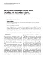
1.1.2 Multipath
The multipath phenomenon is caused by objects (scatterers) lying in the en-
vironment a radio signal is propagating in. Multipath causes the spread of
signals in time and space (and also in frequency if the source is moving), i.e.,
the received signal consists of multiple time-delayed replicas of the transmitted
signal, arriving from various directions. The cause lies in the three basic mech-
anisms that govern wave propagation: reflection, diffraction, and scattering [5].
Reflection occurs when a propagating wave impinges upon an obstruction with
dimensions very large compared with its wavelength. Examples are the earth
surface, buildings, etc. Refraction is a related phenomenon by which a com-
ponent of the radio wave travels into the obstruction medium. Most buildings
are made of materials that absorb a lot of the energy of the wave, such that
the refracted wave is not significant in strength, compared to the reflected one.
CHAPTER 1. INTRODUCTION 6
Reflection
Diffraction
Scattering
Figure 1.2: The propagation mechanisms
Reflection and refraction occur according to Snell’s laws. Diffraction occurs
when the radio path between the transmitter and receiver is obstructed by an
impenetrable object; then, according to Huyghen’s principle, secondary waves
form behind this object. This phenomenon explains how radio waves arrive at
the receiver even though there is no direct line-of-sight, as is the case in most
urban environments. Lastly, scattering occurs when the wave impinges upon
objects of dimensions that are on the order of the wavelength or less. In urban
environments, such scattering objects are street signs or lamp posts. Scattering
causes the energy of the wave to be radiated in many directions. See Figure 1.2
for a sketch of these propagation mechanisms.
The relative importance of these propagation mechanisms depends on the par-
ticular environment. Thus, if there is a direct line-of-sight between the mobile
and base, then reflection dominates the propagation, while if the mobile is in a
CHAPTER 1. INTRODUCTION 7
heavily build-up area with no line-of-sight to the base, diffraction and scattering
will play the major role.
To summarize, multipath propagation results in signal spreading in time (delay
spread), space (angle spread), and frequency (Doppler spread). These three
parameters describe the nature of the wireless communication channels. In a
multipath propagation environment, several time-shifted and scaled versions of
the transmitted signal arrive at the receiver through different paths. The spread
of path delays is called delay spread. Delay spread causes frequency-selective
fading, which implies that fading now depends on the frequency. It can be
characterized in terms of coherence bandwidth, which represents the maximum
frequency separation for which the frequency-domain channel responses at two
frequency shifts remain strongly correlated. The coherence bandwidth is in-
versely proportional to the delay spread [3, chapter 4] and is a measure of the
channel’s frequency selectivity. A small ratio of coherence bandwidth to signal
bandwidth indicates a frequency-selective channel. While delay spread and co-
herence bandwidth are parameters which describe the time dispersive nature of
the channel in a local area, however, they do not offer information about the
time-varying nature of the channel caused by either relative motion between the
mobile and base station, or by movement of objects in the channel. Doppler
spread and coherence t ime are parameters which describe the time varying na-
ture of the channel in a small-scale region. Doppler spread is a measure of the
spectral broadening caused by the time rate of change of the mobile radio chan-
nel and is defined as the range of frequencies over which the received Doppler
spectrum is essentially non-zero. Coherence time is the time domain dual of
Doppler spread. It is actually a statistical measure of the time duration over
which the channel impulse response is essentially invariant, and quantifies the