Development of three dimensional fibrous structures via electrospinning for applications in scaffold based tissue engineering
Bạn đang xem bản rút gọn của tài liệu. Xem và tải ngay bản đầy đủ của tài liệu tại đây (11.87 MB, 180 trang )
DEVELOPMENT OF THREE-DIMENSIONAL FIBROUS
STRUCTURES VIA ELECTROSPINNING FOR
APPLICATIONS IN SCAFFOLD-BASED TISSUE
ENGINEERING
ANDREW KRISHNA EKAPUTRA
(B. Appl. Sc. Hons.) NUS
A THESIS SUBMITTED FOR THE DEGREE OF DOCTOR OF PHILOSOPHY
GRADUATE PROGRAM IN BIOENGINEERING
NATIONAL UNIVERSITY OF SINGAPORE
i
Acknowledgements
My deepest and sincere gratitude goes to both my supervisors, Prof. Dietmar
Hutmacher and Dr. Simon Cool, for their patience, advice and continuous
support towards this project and myself. They have provided me with both
academic and personal guidance throughout my years in graduate school and
inspirations throughout the course of this research project. It was a pleasure
and I am fortunate to be able to work with them.
I am enormously grateful for the unwavering support and love from my
family. Their constant understanding and encouragement kept me going
especially at decisive points in my professional and personal life. I am
eternally thankful to my wonderful wife for her love, patience and selflessness.
Her caring support and absolute confidence in me made me strive for
betterment and the achievement of my academic aspirations.
I would like to thank our collaborator, Dr. Glenn Prestwich, from the
University of Utah, for the generous gift of his material, technical and advisory
support. His work and insights were critical towards the attainment of goals in
this project.
A heartfelt gratitude towards my colleagues and friends I made
throughout the years in the laboratory. Their valued teaching and treasured
insights for me contributed towards the accomplishment of this project. I will
cherish fondly the discussions and occasional laughter we had, for they have
made this journey a memorable one.
ii
Table of contents
Acknowledgements i
Table of contents ii
Summary iv
List of tables vii
List of figures viii
List of abbreviations xviii
List of symbols xxii
Chapter One 1
Background 1
Aims and objectives 3
Research methodology 4
Chapter Two 7
Introduction 7
Scaffold-based tissue engineering 9
Electrospinning and tissue engineering 12
Periosteum and bone healing 16
Chapter Three 19
Electrospinning of PCL and collagen 19
In vitro cell culture characterization by using pig primary bone marrow cells
29
Materials and methods 39
Chapter Four 46
iii
Osteo-conductivity comparison between collagen and gelatin PCL
composites 46
Materials and methods 58
Chapter Five 64
Design and characterization of the fibrous layer 64
Co-electrospinning 65
Cell permeable electrospun scaffolds 71
Materials and methods 79
Chapter Six 85
Angiogenesis and tissue engineering scaffolds 85
In vitro co-culture of EC and fibroblast 88
Electrospun PCL/Col-Hep as a cytokine reservoir 96
In-vitro angiogenesis assay of PCL/Col-Hep loaded with VEGF/PDGF-BB
105
Materials and methods 118
Chapter Seven 127
Conclusions 127
Future works 129
Bibliography 131
Appendices 155
iv
Summary
A vast body of literature shows that the electrospinning technique offers
unique advantages in the production of tissue engineering scaffolds compared
to other methods in terms of simplicity, high surface-to-volume ratio scaffolds
and process versatility. Various reports have been published citing the
suitability of electrospun fibrous meshes as tissue engineering scaffolds due
to their unique physical properties. However, as promising as it may seem,
this technology is still in its infancy and further development is critical before it
can be used for any practical biomedical applications. Moving towards the
next generation of electrospun tissue engineering scaffolds, increasing
research efforts are being focused on issues such as bio-functionalization,
three-dimensionality and improved biomechanical properties of the scaffolds.
The research project outlined in this thesis was aimed to address the
first two issues mentioned. To do so, electrospinning system was setup and
optimized for the fabrication of poly (-caprolactone)-based (PCL) fibrous
meshes. First step of bio-functionalization of the PCL meshes was the
incorporation of a ubiquitous natural extracellular matrix (ECM) protein
component, collagen, creating a synthetic-natural electrospun composite fiber.
The effects of collagen incorporation were investigated with respect to the
resulting mesh’s ability to support in vitro osteogenic morphogenesis.
Compared to PCL alone, its collagen composite (PCL/Col) was proven to be
more osteo-conductive as judged by proliferative capacity of bone marrow
progenitor cells and their development into mature bone-like tissue.
v
Functionalization of the PCL with gelatin yielded a less optimum osteogenic
response compared to collagen.
Addressing the second issue of three-dimensionality of electrospun
scaffolds, a novel hybrid electrospun mesh was fabricated via a modified
electrospinning system. The new system enabled simultaneous
electrospinning of micron-sized PCL/Col fibers with electrospraying of
hyaluronic-acid derived hydrogel, Heprasil
TM
and their combination into a
single scaffold entity. The novel hybrid PCL/Col-Hep mesh allowed cellular
infiltration throughout its architecture as assayed in vitro using a model
osteoblast cell line. This method proved to be significantly better than other
modifications method attempted here. A second step of bio-functionalization
was introduced into this mesh by the incorporation of bioactive growth factors
vascular endothelial growth factor (VEGF), platelet derived growth factor
(PDGF-BB) and bone morphogenetic proteins (BMP-2) within the Heprasil
TM
component. Sustained time-release profiles were obtained through this
method highlighting the potential of the mesh as a cytokine delivery vehicle.
Furthermore, bio-activities of the proteins were retained in this manner
indicating minimal processing damage.
Investigations into the performance of this novel hybrid mesh as a
three-dimensional (3D), bio-functional tissue engineering scaffold were carried
out in an in vitro neo-vascularization model. Co-culture of endothelial cells and
fibroblast were utilized as a model system optimized in a 3D setting on the
PCL/Col-Hep meshes. The fibrous mesh surface properties proved to be
suitable for the culture of both cell types. The interplay of the co-cultured cells
even recapitulated the formation of primitive endothelial capillary networks on
vi
the surface and within the mesh’s interior implying a more physiological
phenotype expression of the cells. Furthermore, similar results were attained
when endothelial cells and fibroblast were cultured on PCL/Col-Hep meshes
impregnated with angiogenic factors VEGF and PDGF-BB and without
exogenous supplementation of the cytokines in the media. This signifies the
potential therapeutic benefits in cytokine delivery in the scaffold.
In conclusion, the work presented in this thesis provided a method of
fabricating the next generation of electrospun scaffolds capable of 3D tissue
integration and bioactive factor delivery. Such a technological advancement
will prove advantageous in achieving improved tissue regeneration and repair.
vii
List of tables
Table 1. Quantitative real time PCR was performed using primers specific for
the amplification of osteogenic marker genes CBFA1, COL1A1, ALP and
OCN. Amplifications of GAPDH genes were used to normalize cDNA input
loading between samples…………………………………………………………62
viii
List of figures
Figure 1. A model of a possible periosteal tissue substitute made of
electrospun fibers. The envisioned scaffolds would have two main layers:
fibrous layer to accommodate three-dimensional highly vascular, fibrous
tissue and cambium layer to house mesenchymal cells capable of assisting
bone repair. 2
Figure 2. A basic electrospinning setup is comprised of polymer solution in a
spinneret being electrically charged by a high voltage generator. At the
threshold, the Taylor cone is formed where polymer material is ejected from
the tip due to electrostatic forces overwhelming the surface tension. A
collector which is set at a different potential is used to attract the ejected
fibers. 13
Figure 3. The periosteum is a fibrous connective tissue covering most outer
parts of the bone (A). It is distinguished into two main components, the fibrous
collagenous layer (marked f in B and C, Masson’s Trichrome stain) and the
cambium layer (marked c in B and C, H & E stain). These two layers are
important in the physiological function and repair of bone. 16
Figure 4. Electrospinning technique was used to fabricate fibrous PCL and its
composite with collagen. A conventional setup (A) consists of a syringe pump
that regulates material flow, a high voltage power supply to generate an
electric field and a charged capillary from which polymer is ejected. A non-
woven mesh is collected over time (B – PCL mesh, C – PCL and collagen
blend mesh) as a result of this process 21
Figure 5. Electrospun fibers of sub-micrometer diameters were produced from
PCL and its collagen composite (PCL/Col) with varying collagen content.
Electron micrographs revealed similar fiber morphology with a tendency for
larger diameters when more collagen by weight was introduced (A – PCL
only, C – PCL/Col 20%, E – PCL/Col 40%, G – PCL/Col 60%). Localization of
ix
collagen was studied using immunofluorescence against collagen type I.
Collagen was found to be presented on the fibers’ surface in all preparations
except for pure PCL (B – PCL, D – PCL/Col 20%, F – PCL/Col 40%, H –
PCL/Col 60%). Bar is 5 m in A, C, E, G; 50 m in B, D, F, H. 23
Figure 6. Mechanical tensile tests were carried out to examine the strength
and the effect of varying amounts of collagen towards the electrospun fibers.
Graphs A to C illustrate the effects of composition towards Young’s modulus,
ultimate stress and ultimate strain of the electrospun meshes. Representative
stress-strain curves of all four fiber preparations are shown in D. In general,
addition of increasing amounts of collagen was found to decrease Young’s
modulus and ultimate stress, and increase ultimate strain of the material.
Asterisks in A-C indicate significant differences between samples (p<0.05). 26
Figure 7. Quantitative analysis of collagen on the surface of PCL/Col 20%
fibers was performed by immunofluorescence accompanied by electron
microscopy. Collagen was still detected on the PCL/Col 20% fiber surface
after in vitro incubation in DMEM for 2, 4 and 7 days (A-C). A three hour
collagenase digestion however rendered the surface collagen undetectable
(D). No morphological changes were visible up to 7 days (E-G) while
collagenase treatment did cause some visible degradation (H). Differential
scanning calorimetry (DSC) analysis was performed on PCL and PCL/Col
20% electrospun fibers (I). It was observed that the addition of collagen into
the structure changed the enthalpy for melting indicating a change in
crystallinity. Bar is 50 m in A-D; 5 m in E-H. 27
Figure 8. Cellular attachment and morphology of the bone marrow cells
(BMC) were observed on both PCL and PCL/Col electrospun scaffolds. After
one day of seeding, cells were more rounded on PCL due to a greater
hydrophobic nature compared to PCL/Col (A). By 14 days of culture,
clustering of cells were observed on PCL scaffolds (both induced and un-
induced) while a more uniform cell distribution was seen in PCL/Col (B). Dy
28 days, full coverage of the surface was observed in all scaffolds except PCL
un-induced (C). Bar is 10 m in A; 100 m in B and C. 30
x
Figure 9. Cellular DNA amount was quantified to study the differences in
cellular proliferation on four scaffold groups (A). Cellular proliferation was
more pronounced on PCL/Col compared to PCL with the same media
composition. Effects of osteogenic induction could be seen in the early burst
of proliferation in PCL/Col and PCL groups. Induced BMC on PCL/Col
showed the highest proliferation rate which peaked and declined after two
weeks of culture. Osteogenic differentiation and maturation of the bony neo-
tissue was evident from the calcium (Ca) mineral deposition on the PCL/Col
scaffolds as assayed by SEM/EDX (B). This tissue maturation and cellular
senescence may be responsible for the apparent decline of cell numbers. Bar
represents 5 m in B. 32
Figure 10. Formation of new tissue on electrospun PCL and PCL/Col
nanofiber scaffolds was studied via histology and immunohistochemistry.
Marked contrast was observed after 14 and 28 days of in vitro culture with
multi-layered tissue formation on PCL/Col induced group. BMC on PCL
scaffolds remained as a monolayer throughout 28 days. Osteogenic marker
proteins; collagen type I, osteopontin and osteocalcin were present in
PCL/Col group with mineralization at 28 days. Marginal expression of collagen
type I and osteopontin was observed on PCL although osteocalcin and
mineralization were not present. This signified that the formation of mature
bone-like tissue only occurred on PCL/Col scaffolds. Bar represents 20 m in
all images. 33
Figure 11. Further studies were conducted by culturing BMC on PCL/Col
nanofiber meshes in a dynamic environment using a spinner flask at 30 RPM
speed (A). Inset in A shows the final constructs after two months of culture.
The BMC were harvested as cell sheets and wrapped around PCL/Col
meshes supported on a glass pipette to create tubular constructs (B).
Compressive tests on the constructs after two months of dynamic culturing
were performed and results are shown in C. Integration of the cell sheet with
the electrospun meshes improved their mechanical strength. Mechanical
xi
anisotropy was observed as the tubular constructs were stronger in the radial
direction compared to axial direction. Bar in A represents 1 cm. 35
Figure 12. Histological analyses were performed via H & E and Safranin-O
staining on the one and two months old constructs to study tissue formation.
After one month culture the constructs showed thick tissue formation on both
sides of the mesh (A, magnified region in B). After two months, three distinct
layers were observed: outer layer (OL), middle layer (ML) and an inner fibrous
tissue (FT) (C, magnified region in D). Strong Safranin-O staining revealed
development of cartilage-like tissue in the middle layer adjacent to the
nanofiber meshes (nf) (E, F). Bar represents 200 m in A, C; 50 m in B, D, E
and F. 37
Figure 13. Osteogenic tissue formation in the two months old tubular
constructs were assayed by Alizarin Red S (ARS; A, region magnified in B)
staining for calcium and immunohistochemistry for collagen type I (Col I; C,
region magnified in D) and osteocalcin (OCN; E, region magnified in F). The
middle layer tissue exhibited a strong presence of calcium and osteocalcin.
Collagen staining was moderately observed throughout the structure. Bar
represents 200 mm in A, C, E; 50 mm in B, D, F. 38
Figure 14. Qualitative differences in morphology and surface properties of
PCL, PCL/Col 20% and PCL/Gel 20% were studied using
immunofluorescence against collagen type I (A-C) and scanning electron
microscopy (D-F). PCL/Gel sample did not posses the collagen type I epitope
on its surface compared to PCL/Col, indicating total denaturation.
Morphologically, PCL/Gel fibers showed similar sizes with a larger distribution
of fiber diameter compared to PCL/Col. Bar represents 50 m in A-C; 5 m in
D-F. 48
Figure 15. Mechanical analyses were performed to study the effects of gelatin
inclusion into PCL structure towards its Young’s modulus (A), ultimate stress
(B) and ultimate strain (C). PCL/Col 20% was included as a comparison. In
general, addition of 20% w/w gelatin into the PCL mesh resulted in a
significant decrease of Young’s modulus and ultimate stress. The resulting
xii
PCL/Gel material was found to be significantly weaker than PCL/Col of the
same weight ratio. Representative stress-strain curves of the three nanofiber
preparations are shown in D. Asterisks indicate significant differences
between two samples. 50
Figure 16. BMC attachment and morphology on PCL (A), PCL/Col 20% (B)
and PCL/Gel 20% (C) were studied using electron microscopy. Cells attached
well although a more rounded morphology was observed on PCL as
previously seen. BMC looked similar in terms of distribution and morphology
on PCL/Col and PCL/Gel. Bar represents 10 m in all images. 52
Figure 17. BMC DNA profile was assayed via the PicoGreen
TM
DNA
quantitation kit. Generally, groups cultured under an osteogenic induction
environment showed more pronounced cellular proliferation at all time-points.
Minimum proliferation was seen in the un-induced PCL group. PCL/Col and
PCL/Gel electrospun meshes allowed more significant cell proliferation. 54
Figure 18. Osteogenic gene expression analyses of BMC cultured on PCL,
PCL/Col and PCL/Gel electrospun meshes. Upstream osteogenic
transcription factor CBFA1 gene was significantly up-regulated in the PCL/Col
group at all time-points (A). The PCL/Col induction group showed significantly
higher up-regulation of COL1A1, ALP and OCN genes (B, C and D). 57
Figure 19. Modifications to the conventional electrospinning setup (A) were
performed to allow different materials to be electrospun (B) or electrosprayed
(C) together with PCL/Col. PCL/Col-Gel and PCL/Col-PEO were fabricated
using simultaneous co-electrospinning on a rotating mandrel. Gelatin and
PEO were then selectively leached out in aqueous solution. Heprasil
TM
, a
hyaluronic acid derivative hydrogel, was electrosprayed into the structure of
PCL/Col mesh as the fibers were deposited on a rotating mandrel. 66
Figure 20. Morphology of the resulting electrospun fibers were studied via
electron microscopy. Conventional electrospun PCL/Col fibers showed
diameters in the sub-micron range (A). Co-electrospinning two fiber materials
yielded meshes with two different fiber groups, noticeable by their differences
xiii
in size (B – PCL/Col-PEO, C – PCL/Col-Gel). A micron-sized PCL/Col
(PCL/Col) mesh was fabricated by means of increased solution
concentration (D, E). Electrosprayed Heprasil
TM
in the PCL/Col-Hep
structure could not be observed under SEM due to the dehydration process
during specimen preparations (E). A graph comparing the difference in fiber
diameters obtained by the different methods is shown in F. Bar represents 5
m in A, B; 20 m in C-E. 67
Figure 21. Fiber visualization was performed by incorporating fluorescent dye
during the electrospinning process. Co-electrospinning results were visualized
by doping the PCL/Col solution with rhodamine (A) and PEO with FITC (B).
This process yielded an electrospun mesh with mixed PCL/Col and PEO
fibers in its structure (C). Subsequent leaching of PEO from the mesh left the
PCL/Col fibers intact (D). Analysis of the embedded Heprasil
TM
was
performed by incorporating AlexaFluor-labelled Bovine Serum Albumin (AF-
BSA) into the hydrogel mix followed by confocal microscopy of the transverse
(E) and planar sections (F). Efficiency of Heprasil
TM
incorporation into the
PCL/Col mesh during the electrospinning process was investigated by
enzymatically digesting the hydrogel and measuring the released AF-BSA. A
graph of efficiency as a function of collection mandrel diameter is shown in G.
Bar represents 50 m in A-F. 69
Figure 22. Cellular attachment and morphology on the five electrospun fiber
groups were analyzed via scanning electron microscopy at three and ten days
of in vitro culture. When cultured on conventional PCL/Col and PCL/Col gel
nanofiber meshes, the cells remained exclusively on the mesh’s surface. Sub-
surface localization of cells was observed in the PCL/Col-PEO mesh. Cellular
infiltration was apparent in the PCL/Col and PCL/Col-Hep meshes. Bar
represents 10 m in all images. 73
Figure 23. Viability of hFOBs on the electrospun meshes were studied
qualitatively using a live/dead cell assay at three and ten days of in vitro
culture. No apparent toxicity was observed when gelatin, PEO and Heprasil
TM
xiv
were used. Their viability was comparable to conventional PCL/Col and
PCL/Col groups. Bar represents 200 m in all images. 74
Figure 24. Cellular infiltration into the electrospun fiber meshes’ structure were
investigated via histological staining (Hematoxylin & Eosin). Cellular infiltration
was not observed in conventional PCL/Col and PCL/Col-gel groups. Marginal
infiltration was seen in the PCL/Col-PEO group after ten days with a majority
of cells still forming cell sheets on the surface. Obvious cellular infiltration was
perceived in the PCL/Col group and was even more pronounced in
PCL/Col-Hep. After ten days of culture, cells were able to penetrate
approximately half of the thickness of PCL/Col and throughout the structure
of PCL/Col-Hep. Arrow heads indicate the stained cell nuclei. Bar represents
50 m in all images. 77
Figure 25. Qualitative comparison of the extent of cellular infiltration into the
scaffolds’ architecture was performed by overlaying a grid system on
histological sections and measuring cell infiltration depth (A). When all the five
groups were compared, PCL/Col-Hep showed the greatest infiltration depth
after three and ten days of in vitro culture (B). Bar in A represents 50 m. 78
Figure 26. A co-culture of HUVEC and IMR90 was performed to determine
their suitability as an in vitro angiogenesis assay of the electrospun meshes.
Cultured HUVEC were stained positive for von Willebrand Factor (vWF) while
IMR90 fibroblast cells did not. When co-cultured together, HUVEC
spontaneously formed capillary-like structures (CLS) in vitro. Bar represents
200 m in all images. 89
Figure 27. A PCL/Col-Hep electrospun mesh was obtained by simultaneous
electrospinning of PCL/Col fibers and electrospraying of Heprasil
TM
hydrogel
(A). Collagen was localized on the surface of these fibers as shown by
immunofluorescence staining (B). A higher resolution image of an area in B is
shown in C. Collagen existed as patches or domains on the PCL/Col fibers.
Cross-sectional and planar fluorescence microscopy was performed to
xv
observe the distribution of Heprasil
TM
in the mesh (D and E respectively). Bar
represents 10 m in A; 200 m in B, D and E; 10 m in C. 91
Figure 28. Cellular morphology and spreading of both HUVEC and IMR90
fibroblast were compared on a tissue culture polystyrene (TCPS) surface and
a PCL/Col-Hep electrospun mesh. On TCPS, both cell types were observed
to be flatter with prominent two dimensional spreading. HUVEC exhibited
typical flat and cobblestone morphology while fibroblast were elongated and
spindle shaped. On the electrospun mesh however, both HUVEC and
fibroblast showed more 3D contacts and features. Bars represent 40 m in
confocal fluorescence microscopy; 10 m in SEM images. 92
Figure 29. Co-culture experiments with HUVEC and IMR90 cells were
performed on the PCL/Col-Hep meshes in order to study their capability of
supporting EC cell functions. HUVEC cultured alone remained as a monolayer
of cells with marginal infiltration into the structure. Sequential seeding (seq) of
IMR90 followed by HUVEC resulted in small islands of EC (*) on the surface.
Better performance was observed when fibroblast and EC were seeded at a
ratio of 3:1 and 5:1 (F:EC). Extensive infiltration by HUVEC was seen in both
groups with the 5:1 group showing CLS formation (arrows) on the surface as
well as in the interior. High density 5:1 ratio seeding resulted in poorer
infiltration and a more confluent surface monolayer. Bar represents 20 m in
H & E images; 50 m in vWF section staining; 200 m in vWF surface
staining. 94
Figure 30. Preliminary protein release experiments were performed with BSA
as model protein. Three different variations of protein loading amount were
assayed. A burst release of protein was observed in all loading with a more
pronounced effect with the highest BSA load. Slow release then ensued over
the course of 28 days where almost all proteins were released. 98
Figure 31. Release profiles of incorporated growth factors VEGF/PDGF-BB
(A) and BMP-2 (B) were assayed to study the suitability of PCL/Col-Hep as
cytokine reservoirs. As observed with BSA, all three growth factors showed
burst release over the first few days. VEGF and PDGF-BB showed immediate
xvi
burst release while BMP-2 had a lag period prior to burst. VEGF and BMP-2
showed slow but continuous release while PDGF-BB stagnated after two
weeks. 101
Figure 32. Bioactivity tests were performed on the released growth factors to
determine their viability. After two days of release, good viability was observed
from VEGF and PDGF-BB (A) and BMP-2 (B). At later timepoints however
marked decrease in bioactivity of VEGF was seen. Slow and gradual
decrease of bioactivity was seen with PDGF-BB and BMP-2 in vitro after three
weeks. 103
Figure 33. Cellular morphology of the co-cultured EC and fibroblast at two
weeks post-seeding was studied via SEM. Co-cultured cells attached well and
covered the electrospun meshes’ surface uniformly in all groups as seen from
the insets. Sub-surface localization of cells was seen in all groups as pointed
out by the arrows. Formation of a more prominent confluent cell sheet was
observed in the –ve control. Distinct formation of endothelial capillaries was
not observed through the electron micrographs. Bars represent 10 m in high
magnification images; 50 m in insets. 107
Figure 34. Formation of EC networks on the PCL/Col-Hep meshes’ surface
was visualized via immunofluorescence staining against EC-specific vWF
proteins. Direct supplementation to the media (+ve control) and loading of
angiogenic factors VEGF/PDGF-BB into PCL/Col-Hep (GF Load) resulted in
prominent EC networks. These networks were characterized by long
extensions of EC CLS with perceptible junctions (white arrows). The lack of
the GFs in the media (-ve control) prevented the networks from forming. Pre-
loading the meshes with GFs did not cause formation of significant EC
networks. Von Willebrand stained red while nuclei stained blue. Bars
represent 200 m in all images. 109
Figure 35. Magnified images of EC junctions in the networks formed on
PCL/Col-Hep surfaces. The images showed that these junctions were
associations of multiple EC. There were indications as well that these
structures also had lumens evident from the imperfect coverage by the EC
xvii
(white arrows). Von Willebrand stained red while nuclei stained blue. Bars
represent 30 m in all images. 110
Figure 36. Infiltration of cells and their distribution was studied via histology
(hematoxylin & eosin) after two weeks post-seeding in all four groups. All
culture groups showed marked cellular infiltration with uniform distribution.
Elongated structures (white arrows) were seen prominently in the +ve control
and GF loaded meshes and to lesser extent, in the pre-loaded mesh. None
were seen in the –ve control. Bars represent 50 m in all images. 112
Figure 37. Endothelial localizations throughout the thickness of the meshes
after two weeks post-seeding were visualized via vWF immunofluorescence in
all four culture groups. Both +ve control and GF loaded meshes exhibited
extensive EC infiltration and network formations throughout the meshes’
architecture. There were indications of lumen formations in the scaffolds’
interior as pointed out by the arrows. Minimum EC infiltration and network was
found in the –ve control. Pre-loading of the scaffolds with GFs resulted in
much less prominent infiltration and EC networks. Von Willebrand stained red
while nuclei stained blue. Bars represent 50 m in all images. 113
Figure 38. Quantitative comparisons were performed to investigate
differences in endothelial network formation and the extent of endothelial cell
infiltrations in the different culture groups. The average length of endothelial
tubules in the +ve control and GF Load samples was quantified (A) by
measuring the lengths of tubules between junctions (sample image is shown
in B, yellow lines indicate measured lengths). No significant differences were
observed between the CLS formed in the +ve control and GF Load. Also,
endothelial penetration in all four culture groups was measured (C) by a
similar grid method used in chapter five to detect the deepest localization of
vWF signal in the cross-sections. No significant differences were seen in
penetration depth of endothelial cells in the +ve control and GF Load. EC did
not penetrate as deep in the Preload group. Bars were 200 m in B and 50
m in D. 114
xviii
List of abbreviations
+ve - Positive
-ve - Negative
2D - Two dimensional
3D - Three Dimensional
3DP - Three Dimensional Printing
AF-BSA - AlexaFluor-Bovine Serum Albumin
ALP - Alkaline Phosphatase
ARS - Alizarin Red S
BMC - Bone Marrow Cell
BMP-2 - Bone Morphogenetic Protein-2
CAD/CAM - Computer-aided Design/Computer-aided Manufacturing
Cbfa1 - Core Binding Factor Alpha 1
CBS - Cytoskeletal Buffer Solution
CLS - Capillary-like Structure
Col I - Collagen type I
Col - Collagen
C
t
- Threshold cycle
DAPI - 4',6-diamidino-2-phenylindole
DMEM - Dulbecco’s Modified Eagle Media
DNA - Deoxyribonucleic acid
DSC - Differential Scanning Calorimetry
EBM-2 - Endothelial Basal Media-2
EC - Endothelial cell
xix
ECM - Extracellular Matrix
EDTA - Ethylenediamine tetraacetic acid
EDX - Energy Dispersive X-Ray Spectroscopy
EGTA - Ethyleneglycol tetraacetic acid
ELISA - Enzyme-linked Immunosorbent Assay
EPC - Endothelial Progenitor Cell
F:EC - Fibroblast to EC ratio
FBS - Fetal Bovine Serum
FDA - Fluorescein diacetate
FDM - Fused Deposition Modeling
FGF - Fibroblast Growth Factor
FITC - Fluorescein iso-thiocyanate
FT - Fibrous tissue
GAG - Glycosaminoglycan
GAPDH - Glyceraldehyde 3-phosphate dehydrogenase
Gel - Gelatin
GF - Growth Factor
GPC - Gel Permeation Chromatography
H & E - Hematoxylin and Eosin
HA - Hyaluronic Acid
HAp - Hydroxyapatite
HD - High density
Hep - Heprasil
TM
HFIP - Hexafluoro isopropanol
hFOBs - Human Fetal Osteoblasts
xx
HRP - Horse Radish Peroxidase
HUVEC - Human Umbelical Vein Endothelial Cell
ICAM-1 - Inter-Cellular Adhesion Molecule-1
IgG - Immunoglobulin G
LCSM - Laser Scanning Confocal Microscope
MES - 2-(N-morpholino)ethanesulfonic acid
ML - Middle layer
MMP - Matrix Metalloproteinase
mRNA - Messenger Ribonucleic Acid
MSC - Mesenchymal Stem Cell
NIH - National Institute of Health
OCN - Osteocalcin
OIC - Osteogenic Induction Cocktail
OL - Outer layer
PAN - Polyacrylonitrile
PBS - Phosphate-buffered Saline
PCL - Poly (-caprolactone)
PDGF-BB - Platelet-derived Growth Factor-BB
PECAM-1 - Platelet Endothelial Cell Adhesion Molecule-1
PEO - Polyethylene oxide
PGA - Polyglycolic acid
PHB - Polyhydroxy butarate
PI - Propidium Iodide
PLA - Polylactic acid
PVA - Polyvinyl alcohol
xxi
qPCR - Quantitative Polymerase Chain Reaction
RGD - Arginine-Glycine-Aspartic acid
RP - Rapid Prototyping
RPM - Revolutions Per Minute
SEM - Scanning Electron Microscope
Seq - Sequential
SLS - Selective Laser Sintering
TCPS - Tissue Culture Polystyrene
TFE - Tetrafluoroethanol
T
g
- Glass Transition Temperature
TGF- - Transforming Growth Factor Beta
TIPS - Thermally-induced Phase Separation
T
m
- Melting Temperature
UV - Ultraviolet
VCAM-1 - Vascular Cell Adhesion Molecule-1
VEGF - Vascular Endothelial Growth Factor
vWF - von Willebrand Factor
xxii
List of symbols
- micro
- epsilon
- beta
- alpha
1
Chapter One
Background
Electrospinning has swiftly gained interests in the tissue engineering field as a
rapid and reliable method of scaffold fabrication. Due to the physical
similarities between the fibers and natural extracellular matrix (ECM), it is
being exploited in the production of ECM-mimetic scaffolds. At its current
development, electrospinning is not without a drawback. Due to the very
nature of their deposition, electrospun fibers prohibit the infiltration of cells into
their architecture. Eventually, this fact will limit the potential use of electrospun
scaffolds as tissue engineering scaffolds.
This thesis was driven by the need to overcome this limitation and to
further develop the electrospinning system as a method of fabricating truly
three-dimensional (3D) tissue engineering constructs. As a preliminary tissue
model, the periosteum was chosen due to its importance in the repair and
regeneration of bone. Furthermore, not much emphasis has been placed in
engineering a functional periosteum substitute. Two independent attempts to
engineer periosteum substitutes were done using collagen sponge grafts for
skin and de-cellularized dermal matrices [1, 2]. These structures, however,
may not be suitable for the reconstruction of the periosteum and possibility of
immune response and pathogen transfer exists when de-cellularized matrices
are involved. Multi-functionalities of the periosteum as a tissue capable of
2
initiating bone healing, vascularization network and a barrier membrane for
soft tissue were not addressed by the models. Thus, explorations into novel
materials and architectures are needed for functional periosteal grafts.
The hypothesis behind this thesis is that a novel synthetic-natural
hybrid fibrous mesh fabricated via modified electrospinning system will
support both bone morphogenesis and recapitulation of vascular networks to
be potentially used as periosteal graft. An envisioned periosteal substitute
produced by the electrospinning technique is shown in Figure 1 below.
Mimicking the native periosteum structure, the scaffold would have a cell-
penetrable fibrous zone for the formation of fibrous tissue and vascular
networks. Beneath this zone, a cambium layer is situated for the possible
delivery of mesenchymal cells to aid underlying bone repair. As an added
functionality, hydrogel-based vehicles may be incorporated into the structure
to permit delivery and time-release of relevant growth factors (i.e. angiogenic
and osteogenic).
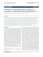
Figure 1. A model of a possible periosteal tissue substitute made of
electrospun fibers. The envisioned scaffolds would have two main layers:
fibrous layer to accommodate three-dimensional highly vascular, fibrous
tissue and cambium layer to house mesenchymal cells capable of assisting
bone repair.