Fabrication, characterization and application of metal tetraaminophthalocyanine polymer nanostructures
Bạn đang xem bản rút gọn của tài liệu. Xem và tải ngay bản đầy đủ của tài liệu tại đây (11.36 MB, 189 trang )
1
Chapter 1
Introduction
2
Introduction
The discovery of carbon nanostructures (fullerenes and carbon nanotubes) in the last
century brought a whole perspective to the semiconductor industry, making the
development applications of silicon-based nanostructures possible. Such
nanostructured materials are often produced in a metastable state, and they are unique
compared to individual atoms/molecules on the one hand, and macroscopic bulk
materials on the other. Their detailed atomic configuration depends sensitively on the
kinetic processes by which they are fabricated. Therefore, the properties of
nanostructures can be widely adjustable by changing their size, shape and processing
conditions. Nanostructures of metals, semiconductors, and inorganic and organic
polymers have drawn a high level of attention not only because they can be widely
employed in the industry, but also for their novel characteristics which could facilitate
the understanding of fundamental theories and mechanisms, for instance quantum and
surface/interface effects.
A protocol combining size-confinement with the electrochemical polymerization
technique may offer a versatile way for the fabrication of useful organometallic
conducting polymer nanostructures. Interesting properties may conceivably appear in
these polymer nanostructures which hold potential for applications in electrocatalysis,
as electrochemical sensors, electronic and photovoltaic devices. In the following
sections, the fabrication strategies, characterizations and potential applications of
3
conducting polymers of metal tetraaminophthalocyanines (MTAPc) in the
nanostructural level will be introduced in detail.
1.1 Conducting Polymers
Conducting polymers (CPs) possess a unique combination of properties as organic
polymer semiconductors, and they are attractive alternatives for materials currently
used in microelectronics. The field of conducting polymers could be traced back to
the mid 1970’s when Shirakawa et al found the first polymer, polyacetylene, which
was capable of conducting electricity [1, 2]. This work eventually resulted in the
award of the Nobel Prize (2000) in Chemistry. Within a few years of the discovery,
progress in the study of conjugated poly-heterocycles [3] was dramatic, and it
motivated the material science community to explore increase in conductivity by
doping the polymers chemically or electrochemically. In these studies, efforts were
made to produce novel materials which combine properties of environmental stability,
mechanical flexibility, and lightness in weight, thereby capitalizing on the easily
processable advantages of an organic polymer with the available electrical properties
of a metal.
1.1.1 Bandgap theory and conduction mechanism
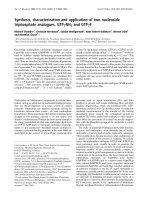
With regard to conduction properties, materials can be classified into three broad
categories: Conductors (or metals), Semiconductors and Insulators. The most
frequently used mechanism to explain these conduction properties may be the band
4
theory. The highest occupied band is the valence band (VB), while the lowest
unoccupied band is the conduction band (CB). The energy spacing between these two
bands is known as the bandgap energy (Eg). For conductors, the VB and CB overlap
and the intrinsic conductivity is attributed to the zero band gap. For semiconductors,
the band gap energy is small and the electrons may be excited by vibrational, thermal
or photon excitation to jump to the CB to render the material conductive. For
insulators, the energy separation is too large for electrons to jump to the CB at room
temperature. In terms of their bandgaps, these three classes are demonstrated in
Figure 1.1.
Fig. 1.1 Band structure of three categories of materials based on conducting properties
Conducting polymers have always been treated as semiconductors from the view-
point of traditional solid-state physics, though conduction in CPs is different from
that in conventional inorganic materials such as doped silicon or GaAs. The bandgap
in CPs is usually above 1.5eV, and thus the intrinsic conductivity is rather low (Table
1.1 shows several important conducting polymers and their conductivities).
5
Table 1.1 Conductivities of several important conducting polymers
Conducting polymer Conductivity (S cm
-1
)
n
Polyacetylene
10
3
~10
5
H
N
n
Polyaniline (Pani)
10
2
~10
3
H
N
n
Polypyrrole (Ppy)
10
2
~10
3
S
n
Polythiophene
10
2
n
Poly(p-phenylene vinylene) (PPV)
10
-3
n
Poly(p-phenylene)
10
3
In order to achieve conductivities comparable to metals, doping process is performed
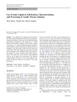
(chemically or electrochemically), and consequently the polaron-bipolaron model has
been widely applied to explain the band structure changes. In chemistry, a polaron is
defined as a radical cation that stabilizes itself by polarizing, while bipolaron is a
6
bound pair of two polarons. By way of an example, these properties are explained for
polypyrrole in Figure 1.2.
Figure 1.2 Band structure evolution and actual structure for polypyrrole upon doping
At zero doping level, the polymer is neutral and its band structure is that of a standard
semiconductor. Upon the oxidative doping of polypyrrole, an electron is removed
from the backbone chain to produce a polaron which is a combination of a charge site
and a radical. The polaron state of polypyrrole is symmetrically located about 0.5 eV
from the CB and VB edges [4]. The partial delocalization of polaron across several
7
monomer units leads to structural distortion in the polymer. On removal of an
additional electron by further oxidation, the free radical of the polaron is removed,
creating a bipolaron. The bipolaron levels are located symmetrically with a band gap
of 0.75 eV from both band edges.
During this process, the entire polymer chains would firstly be saturated with
polarons before bipolaron formation. At even higher doping level, the formation of
individual bipolarons would lead to a continuous bipolaron band. Their band gap also
consequently increases as newly formed bipolarons are made at the expense of the
band edges. The bipolaron bandwidths are about 0.4 to 0.45eV. At such high doping
levels, these spinless bipolarons exhibit high mobility under electrical field and this
explains the generation of high conduction property from doped conducting polymers.
Meanwhile, it is expected that the two bipolaron bands would gradually merge with
the CB and VB to produce near metallic conductivity through partially filled bands.
1.1.2 Fabrication of conducting polymers
The polymerization of a conducting polymer, such as polypyrrole, has been studied in
depth. CPs have been synthesized mainly by three methods: electrochemical
polymerization, chemical polymerization, and chemical vapor deposition. The
electrochemical and chemical polymerization methods will be introduced in this
chapter while the chemical vapor deposition method will be presented extensively in
the next chapter. Chemical polymerization is mostly done through condensation
8
polymerization, while nearly all electrochemical methods are based on addition
polymerization.
1.1.2.1 Electrochemical polymerization
Polypyrroles were produced by oxidative electropolymerization and they are the first
materials synthesized by electrochemical methods in the fabrication of CPs. Very
shortly after that, electrochemical polymerization drew particular interest since it
allows for control of the structure, thickness, conductivity, and electrochemical
properties of the resulting polymer by variation of the experimental conditions. The
conditions that could be varied included film-growing rates (applied potentials and
current densities), supporting electrolytes, temperatures and solvents. Since then,
electrochemical polymerization using a variety of aromatic compounds (as
monomers), such as indole, aniline, phenylene, furan, azulene, fluorene, pyrene and
thiophene [5-9] had been investigated. Figure 1.3 lists some of these monomers
employed for electropolymerization.
Electropolymerization is usually initiated by oxidation via an applied potential to
generate the radical ion in the first step (Figure 1.4; polypyrrole is again taken as the
example here). The population of radical ions far exceeds that of neutral monomer in
the vicinity of the electrode surface. This is in contrast to the situation in typical
chemical polymerizations where the concentration of monomer takes the majority.
The electropolymerization is terminated through the exhaustion of reactive radical
species or other chain termination processes. This is a useful technique for quick and
rapid fabrication of CPs. However, not all monomers undergo electrochemical
9
polymerization. Two main key factors are the potential for the generation of radical
ions and the stability of these ions in the first step.
N
N
M
R
1
R
2
N
N
R
4
R
3
Substituted Porphyrins
N
M
N
N
N
N
N
N
N
R
2
R
3
R
4
R
1
Substituted Phthalocyanines
N
H
Pyrrole
NH
2
Aniline
H
N
Indole
Pyrene
Figure 1.3 Examples of some monomers employed for electropolymerization
10
H
N
H
N
H
N
+ e
-
Potential
applied
Initiation of electropolymerization
H
N
2
N
H
H
H
H
N
N
H
+ 2H
+
Propagation of electropolymerization
H
N
N
H
n
+
H
N
H
N
N
H
+ 2H
+
n+1
Termination of electropolymerization
H
N
N
H
n
H
2
O
H
N
N
H
n
O
Figure 1.4 Generic electropolymerization pathway for many CPs (taking polypyrrole as
example here)
CPs are mostly synthesized by galvanostatic (constant current) and potentiostatic
(constant potential) polymerizations. Potentiostatic polymerization generally yields
polymers with more consistent morphology. Galvanostatic deposition can be used to
control charge for desired thickness, although is it universally accepted that it yields
polymers of poorer morphology and conductivity. Alternatively, a more commonly
used variation of this technique is based on repetitive potential cycling, or cyclic
voltammetry (CV). The potential is continuously changed as a linear function of time
and the direction of the potential is reversed at the end of the first scan. In conducting
11
polymer fabrication, the potential is scanned typically in the range slightly beyond the
monomer oxidation potential and the experiment is performed in a classical three-
electrode electrochemical cell. These conditions result in consistent morphology as
well as desirable control of the thickness by number of cycles. The three electrodes
comprise the working electrode (WE, also called the indicating electrode), reference
electrode (RE) and counter electrode (CE, also known as the auxiliary electrode).
Commonly used reference electrodes are the saturated calomel electrode (SCE,
Hg/HgCl/KCl) and the silver chloride electrode (Ag/AgCl/KCl), while many
materials could be used as counter electrodes. Indium tin oxide (ITO) glass or Pt
wires are preferred working electrodes in electrochemical polymerization for
conducting polymers. The former provides a transparent substrate for electrochromic
and initial characterization studies, while the latter demonstrates excellent adhesion of
most CPs. To prepare free-standing polymer films, graphite or glassy carbon
electrodes may be preferred. The schematic diagram in Figure 1.5 shows a
conventional three-electrode electrochemical cell set up.
Figure 1.5 Typical electrochemical cell setup for cyclic voltammetric electropolymerization.
12
During electropolymerization, it is also noted that the net charge transfer is a little in
excess of the indicated stoichiometric value. This is explained as the additional
oxidation or doping occurring at the same time during polymerization. For example,
in an electropolymerization requiring 2 electrons per monomer molecule, an
experimental charge order of 2.5 would mean that the polymer has undergone 50%
doping in the process. More details relating to such doping will be presented in
Section 1.1.3.
1.1.2.2 Chemical polymerization
Among all the chemical polymerization methods, the most well known is the
Shirakawa method. This is an adapted Ziegler-Natta polymerization used for the
synthesis of stereospecific polymers. Most coupling methods have been adapted from
methods ranging from traditional organic synthesis to condensation polymerization,
e.g. in the formation of poly-phenylene and poly-phenylene vinylene[10].
On the other hand, most chemical polymerization strategies for CPs are based on
addition polymerization. After the initial generation of the radical ion, coupling
occurs between radical and monomer, unlike the radical-radical coupling in
electrochemical polymerization. The second difference is that many chemical
polymerizations are precursor polymerizations. This means that initially a processable
and usually soluble polymer needs to be synthesized, which subsequently yields the
final CP through a few relatively simple chemical steps. Common chemical
polymerization methods are usually simple, involving a monomer, an oxidant (which
could be the dopant as well) and a suitable reaction system (solvent and temperature).
13
For instance, as shown in Figure 1.6, polythiophene can be obtained by
polymerization in the presence of oxidizing agents such as Cu(ClO
4
)
2
, FeCl
3
and
NOBF
4
[11-13]. Polypyrroles have been fabricated by chemical oxidation of the
monomer with ferric salts[14, 15]. Polyanilines can be prepared through
polymerization by specific oxidizing agents e.g. (NH
4
)
2
S
2
O
8
or common ones such as
Fe(ClO
4
)
3
or Cu(BF
4
)
2
[16].
S
S
+
S
S
H
H
S
+
S
S
H
H
S
H
-H
+
-H
+
-e
S
S
H
S
H
n
Figure 1.6 A Proposed Chemical Polymerization Mechanism for Polythiophene [11].
Several novel alternative polymerization methods have been developed. For instance,
a polypyrrole was prepared by the direct photosensitization of Ru(bpy)
3
3+
using a 490
nm dye laser in a matrix of Nafion [17]. By using a solvent evaporation method (the
solvent was evaporated to increase the concentration of oxidant), the same
polypyrrole was formed using FeCl
3
in a polyvinyl acetate matrix in methanol solvent
[18]. A semi-soluble sulfonated polyaniline was “enzymatically” synthesized by
treatment with enzyme horseradish peroxidase [19]. It was also noted that this
polymer could be self-assembled into multilayer structures. Polyaniline was also
reported to be synthesized by plasma polymerization using radio-frequency (RF)
glow discharges with resistive coupling between stainless steel electrodes at a
14
frequency of 13.5MHz and pressure around 2×10
-2
Torr [20]. Other unique
polymerization methods also include oriented polymerization [21], chemical vapor
deposition [22] and chemical template polymerizations [23].
Chemical polymerized CPs have been obtained with comparable or even better
conductivity than those prepared by electropolymerization. However, it is more
difficult to control the morphology, conductivity, doping and composition in chemical
polymerization due to the need for more careful control of reaction conditions like the
reaction temperature, concentration and many other factors. Occasionally, even the
same synthetic procedure may not consistently yield exactly the same polymer.
1.1.2.3 Doping Techniques
Borrowing strategies from traditional p/n type doping semiconductors, it is deduced
that oxidation would generate a positively charged CP with an associated anion, while
reduction produces a negatively charged CP and its associated cation. These
associated ions are called dopants. Typical dopants are listed in Table 1.2, and they
could be small anions like I
-
, or bulk species such as polyvinyl sulfonic acid. The
extent of a doping process is called doping level and this is usually measured as the
proportion of dopant incorporated per monomer unit. Increased doping level leads to
increased conductivity by increasing the number of mobile charges. Nevertheless, it is
generally impossible to have a CP with 100% doping level because of various
constraints in polymers.
15
Table 1.2 Typical dopants for CPs
Dopant Structure / Formula
Anionic
Chloride Cl
-
Polystyrene sulfonated (PSS) [-CH
2
CH(C
6
H
4
SO
3
)-]
n
n-
Hexafluorophosphate PF
6
-
Perchlorate ClO
4
-
Tetrafluoroborate BF
4
-
Trifluoromethane sulfonated (Trifl) CF
3
SO
3
-
p-toluene sulfonated (Tos) CF
3
-C
6
H
5
-SO
3
-
Cationic
Proton H
3
O
+
Sodium Na
+
Most dopants are incorporated into CPs during the process of polymerization.
However, dopants may also be introduced after the formation of CPs by chemical or
electrochemical means. For instance, when a positive potential is applied to a CP, the
dopant anions from the solution will move in the polymer towards delocalized charge
sites. Anionic doping occurs and this is termed as p-type doping. Conversely, when a
negative potential is applied, cationic or n-type doping will happen. Doping may also
not be homogeneous, and doped polyacetylene has been reported to consist of heavily
doped islands surrounded by lightly or undoped insulating polymers [24].
16
Besides these two traditional main methods, alternative doping techniques have also
been developed in the last two decades. Photochemical doping uses irradiation such
as UV or X-ray radiation to treat pristine CPs [25, 26]. In methods widely used in
microelectronics, ion implantation is introduced to CPs to produce doped polymers by
bombardment with high energy ions. Another interesting method is heat treatment
doping [27]. Ladder-type CPs such as the benzimidazolebenzophenanthroline-type
ladder (BBL) has been formed by heat treatment at different temperatures, yielding an
enhancement of conductivity [27]. Such results are attributed to the improved
structure order and thermally excited charge carriers. Just as in the case of
photochemical doping, “dry doping” is developed combining heat treatment by using
heat-generated active dopants (thermally decomposed) to incorporate CPs [28]. This
latter method could be carried out without the assistance of solvent, electrochemical
environment or radiation.
Although many techniques have been developed for the fabrication of novel CPs,
there is a lack of information on the morphology and theoretical studies related to
their conductivity. In certain cases, even models for disordered materials from
condensed matter physics could hardly be applied to CPs. While some attention has
been given to bulk properties of such materials, the same cannot be said of studies on
a micro-scale level apart from the one reported by Martin et al in 1990 on a series of
CP nanostructures [29-34].
17
1.2 Nanostructured Materials
The word "nano" means a billionth (10
-9
) part of a unit in general. Nanostructures or
nanostructured materials refer to material systems with length scale in the range of
around 1 to 100 nm in at least one dimension. Nanostructures are unique materials as
compared with individual atoms/molecules on the one hand or the macroscopic bulk
materials on the other. Interesting properties may arise from nanoscale structures that
do not exist in the same materials in the other scale ranges.
1.2.1 Background and quantum mechanics
For common materials in the bulk such as a gold brick or water, their intrinsic
physical properties are independent of the sizes. For instance, if the gold brick was
cut into small pieces, its density, conductivity or chemical reactivity remains the same.
However, if the cutting process is repeated again and again until gold atoms are
obtained for instance, then these properties could not be kept unchanged. Significant
changes show up as the materials get down to the nanoscale level. The properties of
nanostructured materials are affected by several effects: quantum confinement,
quantum coherence and surface/interface effects [35].
In a nanostructure, electrons are confined in the nanoscale dimension(s), but are
freely moving in other dimension(s). This results in quantization of energy and
momentum, and reduced dimensionality of electronic states. From the perspective of
18
quantum confinement, nanostructures could be classified based on the dimensions in
which electrons are free to move:
Quantum well: electrons are confined in one dimension (1D), free in the other two
dimensions (2D). It can be realized by sandwiching a narrow-bandgap semiconductor
layer between the wide-gap ones. A quantum well is often called a 2D electronic
system.
Quantum wire: confined in 2D and free in 1D. Thus, it is usually called a 1D
electronic system. Quantum wires include polymer chains, nanowires and nanotubes.
Quantum dot (QD): electrons are confined in all dimensions, as in clusters and nano-
crystallites
For electrons moving in a nanostructure, certain phase relation of wave function is
preserved and wave interference effect has to be considered. Nevertheless, in
nanostructures, the quantum coherence generally is not maintained perfectly
compared with atoms or molecules. The coherence is often partially discontinued by
defects in the nanostructures. Therefore, both quantum coherent and de-coherent
effects have to be considered and consequently the description of electronic motion in
a nanostructure becomes more complicated.
Many nanostructured materials are exposed to environmental conditions as part of
their application. Surface effects such as surface chemistry, oxidation and adsorption
may dominate the behavior of these materials because a significant fraction of atoms
in nanostructure is located at or near the surfaces/interfaces. The mechanic,
19
thermodynamic, electronic, magnetic, optical and chemical states of these atoms can
be quite different from those of the interior atoms[36]. Slight modification at the
surface may result in considerable changes in the mechanical properties of
nanostructures such as resonance frequency and quality factor. On the other hand,
defects generated at the surface may cause the rearrangement of existing bulk defects
which consequently produces unique properties. These changes can have dramatic
consequences for the stability and reliability of devices utilizing these properties.
These factors all play important roles but to different extents. Nanostructured
materials are often in a metastable state and their detailed atomic configuration
depends sensitively on the kinetic processes in which they are fabricated. Therefore,
by controlling their size, shape and processing conditions the properties of
nanostructures can be widely adjusted.
1.2.2 Fabrication of Nanostructures
In the past 20 years, inorganic nanostructures have been applied extensively in
microelectronic, optical, and mechanic devices, and in biomaterials and materials for
drug delivery [37-39]. Development in more advanced fabrication strategies of
nanowires and nanotubes to improve this nano technology is ongoing, since every
strategy used presently has its limits and are only suitable for fabricating certain kinds
of nanostructure material. Self-assembly is one popular strategy which has shown
great success [40], although for this process, chemicals, reaction environment and
impurities control are relatively critical. Apart from their use in the imaging of nano-
20
scale materials, STM (Scanning tunneling microscopy) and AFM (Atomic force
microscopy) have also been applied in fabricating nanostructures based on
manipulation of individual atoms [35, 41]. However two disadvantages have hindered
their utilization - they are time consuming methods and require relatively stringent
environment. Patterning lithography is another popular technique, and it has been
widely used in industry because of its high productivity [42, 43], although diffraction
effect limits its further improvement since the critical dimension has already reached
100nm.
1.2.2.1 Lithography and manipulation
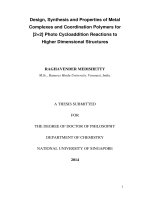
Photolithography is an important process in microelectronic processing by
lithography for making small features on the printed circuit board[44]. Firstly, the
circuit design is converted to patterns using computers and these patterns reflect
particular device and interconnection layout. Then, the patterns are physically created
as masks using lithography such as optical or electron-beam pattern generator. Lastly
the patterns on the masks are transferred to Si wafers. This process is realized by
using a layer of photoresist material coated on the wafer. As shown in Figure 1.7, the
photoresist material in the areas not covered by the mask is exposed to UV radiation,
and certain changes occur after the exposure. With the positive resist layer (resist to
UV radiation and protect the layer underneath) that is usually used today, the exposed
part of this layer becomes easily dissolvable in the developer solution to leave behind
the uncovered silicon oxide. Consequently, processing steps such as etching, film
deposition and ion implantation can be performed in these regions. However, the
21
resolution in the printing process is also limited by the diffraction effect, especially
when UV light is used as radiation source[45-47]. In order to further decrease the
minimum feature size, shorter-wavelength radiation (such as deep UV, X-ray, e-beam
and ion beam) may be introduced [48]. Unfortunately, the lack of effective optical
systems and suitable resist materials are the main obstacles for the applications of the
X-ray and deep UV radiation sources. For e-beam and ion beams, the problem arose
from the strong interaction between the beams and resist material; such interaction
leads to the relatively rough edges of the lithographic pattern. Additionally, mask
alignment uncertainty also imposes a limit on the scale resolution, especially when
more than one mask is used.
Figure 1.7 Stages of Photolithography.
The most remarkable example of manipulation is the construction of a quantum corral
consisting of 48 iron adatoms on a copper(111) surface [49, 50]. In the imaging
mode, the STM tip is usually positioned far away from the adatoms and thus the
22
interaction is weak. When an increased tunneling current or a reduced bias voltage is
applied, the distance between the tip and the sample decreases and the interaction
then becomes strong enough for the manipulation of the atoms. When an even higher
bias voltage is applied, it is possible to pick up the adatoms and even the atoms in
surface layer by means of the extremely strong attractive force [51]. Such atomic
lithography is normally controlled by bias voltage pulses and thus atoms on the tip
can be selectively deposited on the surface. On the other hand, local chemical or
electronic states of the surface or adsorbates can be modified by the electric field
and/or electron beams generated by the SPM tip [52, 53]. For example, local
oxidation can be induced by the electric field generated with a SPM tip on substrates
such as silicon, and oxide patterns can be written on these substrates. Nevertheless,
from the industry viewpoint, these processes are extremely time-consuming and often
require ultra-high vacuum (UHV) conditions. Thus, real applications from them could
hardly be realized.
1.2.2.2 Self-assembly strategies
Nanostructures can also be formed by self-assembly methods which do not require
the use of masks or fine-focused beams. Self-assembly has numerous advantages as a
strategy in nanotechnology [7, 54, 55]. Firstly, it takes the advantages of some
energetic, kinetic or geometric effects in the growth process to carry out many
difficult steps in nanofabrication. Secondly, in the atomic-level modification of
structures, it preferentially forms a thermodynamically stable product with fewer
defects. Thirdly, numerous examples could be derived from biological systems to
23
help in the design of self-assembly strategies which produced structures that are
biologically incorporation-ready. Lastly, self-assembly is generally a parallel process
since many nanostructures are formed simultaneously during their fabrication
process. This makes it one of the most promising methods in industrial
nanofabrication.
Multi-layers of QDs (Ge with a pyramidal structure on silicon surface) are fabricated
with uniform size and distribution by taking the advantage of the Stranski-Krastanov
growth mode [56]. A stacked structure of self-assembled GaSb/GaAs QDs has been
grown by molecular beam epitaxy in the same mode [57]. QDs in different layers are
correlated in position due to elastic interaction between them. Also, there are many
self-assembly processes for the fabrication of nanostructures by chemical methods.
Self-assembled monolayers (SAMs) of thiolates have been fabricated with noble
metals making use of the high affinity of thiols towards these metals [58]. The SAMs
can act as surfactants for other nanostructures as chemical templates. Hexagonal array
of pores with high aspect ratio can be formed on alumina during the anodized process
of aluminum [59-62], and similar structures of porous silicon have been produced by
immersing the silicon wafer as the anode in hydrogen fluoride (HF) electrolyte[63,
64]. Subsequently, pure metal nanostructures have been synthesized using anodic
aluminum oxide (AAO) membranes as physical templates [65-69]. These templates
have also been used in the fabrication of a whole array of other materials [70-80].
The key issues that make self-assembly a useful strategy are the effective controls of
size, shape and positioning of individual nanostructures fabricated. Such controls can
24
be achieved by the proper selection of the process condition which allows for taking
advantage of some intrinsic material properties. On the other hand, using self-
assembled nanostructures as template to combine other fabrication strategies of
nanomaterials should provide a more versatile and convenient way to fabricate other
nanomaterials.
1.2.2.3 Template-assisted strategies
Template-assisted strategies, especially those involving the use of chemical templates,
are widely used to prepare hollow nanostructures [81]. The chemical template
strategy allows the formation of a polymer shell around a preformed template particle
which can be removed subsequently. Therefore, it is one of the most promising
approaches in the production of polymeric hollow nanospheres due to its relative ease
of operation. Inorganic nanoparticles are used as templates, and the polymerization
reaction can be either catalyzed by an initiator or by the colloidal particles themselves
[82-84]. Through layer-by-layer deposition, oppositely charged polyelectrolytes are
deposited step-by-step to produce the well-known polyelectrolyte self-assembly at
charged surfaces and this process has been applied as a template to prepare a series of
nanomaterials [85-91]. Melamine-formaldehyde particles have been widely used as
template particles without affecting the layered polyelectrolyte shells [92-95]. They
have the advantage of being soluble when exposed to an acidic solution.
On the other hand, physical template-assisted fabrication (mostly using AAO
template) has a number of interesting and useful features. First of all, the uniform
25
hexagonal channels make it convenient to introduce various materials into the
template by general approaches, such as vaporization, evaporation, microemulation
and electropolymerization. A series of electronically conductive polypyrrole
nanostructures have been fabricated by electrochemical methods in template and
characterized by the pioneer Martin’s group since 1989 [29-32]. Interesting electronic,
electrochemical and optical properties have been studied [33]. Metal nanowire arrays,
metal oxides and sulfides nanostructures such as Ag, TiO2 and CdS have been
fabricated by electrodeposition [69, 72, 75] in the last ten years. Highly-aligned
nanotubes arrays have been synthesized by a few groups recently using chemical
vapor deposition techniques based on the template [73, 78, 80, 96]. Moreover,
extraordinarily small diameters (less than 10nm) of the template can be achieved by a
relatively simple process of adjusting different reaction conditions, e.g. acid types and
temperatures [60, 61]. The length of the channels and pore density could be well-
controlled in the same manner. Wu and Bein [97] reported the fabrication of
polyaniline nanostructures with controlled diameters of 3nm, which is difficult even
for usual lithography process. Lastly, the template itself could be easily removed
either chemically (dissolved in acid or base) or physically (laser etching) which is
greatly advantageous in industrial application. All in all, these advantages make it a
versatile strategy in nanostructured materials fabrication and CPs nanostructures have
received particular benefits from the method because of this inorganic, well-
structured and easily-removable template.