Computational analysis of a permanent magnet synchronous machine using numerical techniques
Bạn đang xem bản rút gọn của tài liệu. Xem và tải ngay bản đầy đủ của tài liệu tại đây (3.09 MB, 285 trang )
COMPUTATIONAL ANALYSIS OF A
PERMANENT MAGNET SYNCHRONOUS
MACHINE USING NUMERICAL
TECHNIQUES
DONG JING
A THESIS SUBMITTED
FOR THE DEGREE OF DOCTOR OF PHILOSOPHY
DEPARTMENT OF ELECTRICAL & COMPUTER ENGINEERING
NATIONAL UNIVERSITY OF SINGAPORE
2004
Acknowledgments
First of all, I would like to express my most sincere appreciation and thanks to
my supervisor, Prof. Mohammed Abdul Jabbar, for his guidance and constant
encouragement throughout my four years of postgraduate studies. His help and
guidance have made my research work a very pleasant and fulfilling one. I am also
grateful to my co-supervisor, Dr. Liu Zhejie, for providing me with many suggestions throughout the course of my work.
I would like to thank Dr. Fu Weinong from Data Storage Institute, for his
valuable suggestions and discussions throughout this work. I am also thankful to
Dr. Bi Chao, Senior Research Engineer in Data Storage Institute, for his suggestions and help in this work.
I would also like to express my appreciation to the laboratory technologists,
Mr. Y. C. Woo and Mr. M. Chandra for their support and help, without which
this research work would have been so much harder to complete.
I would also like to thank my colleagues in the EEM Lab - Ms. Qian Weizhe,
Mr. Liu Qinghua, Mr. Zhang Yanfeng, Mr. Yeo See Wei, Mr. Anshuman Tripathi
and Mr. S. K. Sahoo, for their valuable discussions, suggestions and helps throughout my work. Many thanks to all my friends in the EEM Lab - Ms. Hla Nu Phyu,
Mr. Nay Lin Htun Aung, Mr. Azmi Bin Azeman, Ms. Wu Mei, Ms. Xi Yunxia,
i
Miss Wu Xinhui and Miss Wang Wei, who have made my research work in this lab
a very pleasant one.
Finally, I would like to express my most heartfelt thanks and gratitude to my
husband and my family, who have always provided me their support and encouragement. I thank them for their concerns and prayers.
ii
Contents
Acknowledgement
i
Summary
viii
List of Symbols
xii
List of Figures
xiv
List of Tables
xviii
1 Introduction
1
1.1
Permanent Magnet Machines
. . . . . . . . . . . . . . . . . . . . .
1
1.2
Permanent Magnet Materials . . . . . . . . . . . . . . . . . . . . .
3
1.3
Line-Start Permanent Magnet Synchronous Machines . . . . . . . .
7
1.4
Computational Analysis of Permanent
Magnet Machines . . . . . . . . . . . . . . . . . . . . . . . . . . . .
10
1.4.1
Analytical Methods . . . . . . . . . . . . . . . . . . . . . . .
11
1.4.2
Numerical Analysis . . . . . . . . . . . . . . . . . . . . . . .
12
1.5
Analysis of Electric Machines Using Finite Element Method . . . .
13
1.6
Parameter Determination of Permanent Magnet Synchronous Machines . . . . . . . . . . . . . . . . . . . . . . . . . . . . . . . . . .
1.7
15
Scope of the Thesis . . . . . . . . . . . . . . . . . . . . . . . . . . .
17
2 Mathematical Modelling of Line-Start Permanent Magnet Syn-
iii
chronous Machines
19
2.1
Introduction . . . . . . . . . . . . . . . . . . . . . . . . . . . . . . .
19
2.2
Representation of Permanent Magnets . . . . . . . . . . . . . . . .
21
2.3
Modelling of Electromagnetic Fields . . . . . . . . . . . . . . . . . .
23
2.4
Circuit Equations . . . . . . . . . . . . . . . . . . . . . . . . . . . .
27
2.4.1
Representation of a Conductor . . . . . . . . . . . . . . . . .
28
2.4.2
Equivalent Circuits of Stator Windings . . . . . . . . . . . .
30
2.4.3
Modelling of Rotor Cage Bars . . . . . . . . . . . . . . . . .
36
2.4.4
Modelling of External Circuit Components . . . . . . . . . .
43
2.5
Equation of Motion . . . . . . . . . . . . . . . . . . . . . . . . . . .
48
2.6
Conclusion . . . . . . . . . . . . . . . . . . . . . . . . . . . . . . . .
49
3 Finite Element Analysis of Line-Start Permanent Magnet Synchronous Machines With Coupled Circuits and Motion
51
3.1
Introduction . . . . . . . . . . . . . . . . . . . . . . . . . . . . . . .
51
3.2
Summary of the Equations . . . . . . . . . . . . . . . . . . . . . . .
52
3.3
Domain Discretization . . . . . . . . . . . . . . . . . . . . . . . . .
54
3.4
The Choice of Shape Functions . . . . . . . . . . . . . . . . . . . .
55
3.5
Deriving Finite Element Equations Based on the Method of Weighted
Residuals . . . . . . . . . . . . . . . . . . . . . . . . . . . . . . . .
3.5.1
Finite Element Formulation of Field Equations . . . . . . . .
61
3.5.2
Finite Element Formulation of Stator Phase Circuit Equation 65
3.5.3
3.6
59
Finite Element Formulation of Cage Bar Equation . . . . . .
67
Discretization of Governing Equations in Time Domain . . . . . . .
68
3.6.1
Discretization of Field Equation . . . . . . . . . . . . . . . .
70
3.6.2
Discretization of Equation for Stator Phase Circuit . . . . .
71
3.6.3
Discretization of Governing Equations for Cage Bars . . . .
71
3.6.4
Discretization of Equations for External Circuits
72
iv
. . . . . .
3.6.5
Discretization of Equations for Mechanical Motion . . . . . .
72
Solving the Nonlinear Equations . . . . . . . . . . . . . . . . . . . .
73
3.7.1
Linearization of Field Equation . . . . . . . . . . . . . . . .
75
3.7.2
Linearization of Stator Phase Equation . . . . . . . . . . . .
80
3.7.3
Linearization of Equations for Cage Bars . . . . . . . . . . .
82
3.7.4
Linearization of Equations for External Circuits . . . . . . .
83
Assembly of All the Equations . . . . . . . . . . . . . . . . . . . . .
84
3.8.1
Assembly of the Element Equations . . . . . . . . . . . . . .
84
3.8.2
Global System of Equations . . . . . . . . . . . . . . . . . .
86
Application of Boundary Conditions . . . . . . . . . . . . . . . . . .
89
3.9.1
Dirichlet Boundary Condition . . . . . . . . . . . . . . . . .
89
3.9.2
Periodical Boundary Condition . . . . . . . . . . . . . . . .
91
3.10 The Storage and the Solution of the System of Equations . . . . . .
95
3.10.1 The Storage of the Coefficient Matrix . . . . . . . . . . . . .
95
3.10.2 Solving the Global System of Equations . . . . . . . . . . .
98
3.11 The Calculation of Electromagnetic Torque . . . . . . . . . . . . . .
99
3.11.1 Introduction . . . . . . . . . . . . . . . . . . . . . . . . . . .
99
3.7
3.8
3.9
3.11.2 Calculation of Torque with Maxwell Stress Tensor Method . 101
3.12 The Simulation of Rotor Motion . . . . . . . . . . . . . . . . . . . . 103
3.12.1 Meshless Air Gap . . . . . . . . . . . . . . . . . . . . . . . . 104
3.12.2 Meshed Air Gap . . . . . . . . . . . . . . . . . . . . . . . . 105
3.12.3 Simulation of Rotor Motion with Method of Moving Band . 107
3.13 Conclusion . . . . . . . . . . . . . . . . . . . . . . . . . . . . . . . . 113
4 Parameter Estimation of the Line-Start Permanent Magnet Synchronous Machines
4.1
114
Introduction . . . . . . . . . . . . . . . . . . . . . . . . . . . . . . . 114
v
4.2
Lumped Parameter Model of Permanent
Magnet Synchronous Machines . . . . . . . . . . . . . . . . . . . . . 116
4.3
Parameter Estimation of Line-Start
Permanent Magnet Synchronous Machine . . . . . . . . . . . . . . . 123
4.3.1
Working Model in This Work . . . . . . . . . . . . . . . . . 124
4.3.2
BH Characteristic of Lamination Material . . . . . . . . . . 125
4.3.3
Review of Previous Experimental Methods for
Parameter Estimation . . . . . . . . . . . . . . . . . . . . . 126
4.3.3.1
4.3.3.2
Sensorless No-Load Test . . . . . . . . . . . . . . . 132
4.3.3.3
4.3.4
DC Current Decay Measurement Method . . . . . 126
Load Test Method . . . . . . . . . . . . . . . . . . 134
New Methods for Parameter Determination . . . . . . . . . 139
4.3.4.1
Combination of Load Test and Linear Regression . 139
4.3.4.2
Combination of Load Test and Hopfield Neural Network . . . . . . . . . . . . . . . . . . . . . . . . . . 144
4.3.5
Parameter Determination Using Finite Element Method . . 154
4.3.5.1
Inductance Calculation Using Finite Element Method154
4.3.5.2
Evaluation of Machine Parameters by Applying a
Small Change in Current Angle . . . . . . . . . . . 156
4.4
Conclusion . . . . . . . . . . . . . . . . . . . . . . . . . . . . . . . . 158
5 Dynamic Analysis of a Line-Start Permanent Magnet Synchronous
Machines with Coupled Circuits
161
5.1
Introduction . . . . . . . . . . . . . . . . . . . . . . . . . . . . . . . 161
5.2
Experimental Setup of the PMSM Drive . . . . . . . . . . . . . . . 163
5.3
Methodology and Modelling for Analysis . . . . . . . . . . . . . . . 167
5.3.1
Modelling of the Fields . . . . . . . . . . . . . . . . . . . . . 167
5.3.2
Modelling of the Stator Phase Circuits . . . . . . . . . . . . 168
vi
5.3.3
Modelling of the Rotor Bars . . . . . . . . . . . . . . . . . . 170
5.3.4
Modelling of the External Circuits . . . . . . . . . . . . . . . 172
5.3.5
Modelling of the Rotor Motion
. . . . . . . . . . . . . . . . 173
5.4
Evaluating the EMF due to the Permanent Magnets . . . . . . . . . 173
5.5
The Self-Starting Process of the PMSM . . . . . . . . . . . . . . . . 174
5.5.1
5.5.2
Results of Self-Starting at No-Load (TL = 0N · m) . . . . . . 175
5.5.3
Results of Self-Starting With Load (TL = 8N · m) . . . . . . 181
5.5.4
5.6
Procedure of Computation . . . . . . . . . . . . . . . . . . . 174
Results of Self-Starting With Various Loads . . . . . . . . . 184
The Starting Process Under V/f Control . . . . . . . . . . . . . . . 185
5.6.1
5.6.2
5.7
The Control Scheme . . . . . . . . . . . . . . . . . . . . . . 185
Computational and Experimental Results
. . . . . . . . . . 186
The Starting Process Under Vector Control . . . . . . . . . . . . . . 190
5.7.1
5.7.2
5.8
The Control Scheme . . . . . . . . . . . . . . . . . . . . . . 190
Computational and Experimental Results
. . . . . . . . . . 191
Conclusion . . . . . . . . . . . . . . . . . . . . . . . . . . . . . . . . 194
6 Conclusions and Discussions
196
References
202
Publications
221
A The Newton-Raphson Method
223
A.1 Application to Single Nonlinear Equation . . . . . . . . . . . . . . . 223
A.2 Application to a System of Equations . . . . . . . . . . . . . . . . . 225
B The Derivation of
∂B
∂A
227
C The Representation of Nonlinear B − H Curve
vii
229
D The Method of BICG
232
E The flowchart of the Field-Circuit Coupled Time Stepping Finite
Element Method
235
F Motor Specifications and Dimensions
237
G Determination of the B − H Characteristic of the Stator Iron
240
H Experimental Data Tables for Parameter Determination
244
I
250
The Inverter Circuit
J Parameters of PMSM
252
K Determination of Moment of Inertia and the Coefficient of Friction
258
L Equations used in the Mid-symmetrical PWM Generation
viii
262
Summary
This thesis deals with computational analysis of a line-start permanent magnet synchronous motor (PMSM) using finite element method (FEM). Electric machines
receive power from external sources through electric circuits. The objective is to
couple all the circuits directly with field calculations in order to make it a voltage
source driven system as opposed to a current source driven system normally used in
FEM computations. We studied both static as well as dynamic operations of this
machine under various starting conditions for the dynamic analysis of PMSM. Motor parameters are important elements in the dynamic operations. We have studied
many existing methods of parameter determinations and critically examined their
suitability and shortcomings. We have developed two new methodologies for the
determination of two-axis motor parameters using mathematical models and experimental measurements.
Field - circuit coupled time stepping FEM is used to study the dynamics of
PMSM. In the computation, 2D models combined with various circuits are used.
Maxwell’s equation is used to model the 2D electromagnetic fields. The 3D effects
due to the stator end windings and rotor end rings are simplified by circuit models.
The parameters of these end effects, which are calculated by analytical methods,
are included in the circuits. The semiconductor components in the external electric circuits are modelled as resistors with different resistance values depending on
their operating status. Electric machines are electro-mechanical conversion devices;
ix
hence mechanical movement of the machine governed by the kinetic equation is also
included in our computational process.
Finite element method is implemented for the field equations. The space
dependent quantities in the equations are formulated by the principle of weighted
residuals. The time dependent quantities are evaluated by the backward Euler’s
method. Various circuit equations are assembled and solved simultaneously with
the field equations. The nonlinearities brought along by permanent magnets and
the soft magnetic materials are handled by Newton-Raphson’s method, and cubic
splines are used to represent the characteristics of the nonlinear materials. The
resultant global system of equations is non-symmetric; and a bi-conjugate gradient
method is used to get the solution of these equations in each Newton-Raphson iteration. With the electromagnetic field solutions, the motor torque at each instant
of time step is calculated using the method of Maxwell stress tensor. The dynamics
of the PMSM is computed using a step by step procedure.
The starting process is complicated by the asynchronous torque and rapidly
changing slip.
This has been computed using co-ordinate transformation and
through eddy current modelling. Both the process of self-starting and the starting
under controls are computed. The control schemes included the V/f control and
the vector control. The good match of the computational results with the experimental results suggests that the time stepping FEM with coupled circuits can be
a good tool for computing the dynamics of a PMSM.
In the determination of PMSM parameters, experimental methods used recently by many researchers have been reviewed. These methods include the DC
current decay method, sensorless no-load test method and the load test method.
x
Analysis and experimentations show many shortcomings and inaccuracies involved
in those methods. Some methods cannot provide complete parameter information;
some involved complicated and weak experimental procedures that bring inaccuracies in the results. To overcome the drawbacks of the previous methods, two
new methods have been proposed based on the load test method. Linear regression
model and Hopfield neural network are used in combination with the load test to
determine the machine parameters. Results obtained by these new methods are
compared with those obtained by other researchers. The comparison shows great
improvements made by these new methods in the parameter determination.
FEM is also applied to calculate the parameters. The saturation effects of
stator current on the parameters are taken into account in the calculations as well.
The agreement between the FEM results and the experimental results indicates
that FEM is useful and applicable in predicting the PMSM parameters.
xi
List of Symbols
A
magnetic vector potential
B
flux density
H
external applied field intensity
M
magnetization vector
µ
magnetic permeability
µ0
magnetic permeability in the free space
µr
relative permeability
ν = 1/µ magnetic reluctivity
χm
magnetic susceptibility
Br
remanent flux density
Hc
magnetic coercive force or coercivity
J
current density
E
electric field intensity
σ
electric conductivity
is
stator phase current
ia , ib , ic
phase a, b and c stator currents
s
cross section area of one turn of phase windings
t
time
Vs
applied stator phase voltage
Rs
total stator resistance
Ns
equivalent number of turns per phase
Le
inductance of stator end windings
l
axil length of stator iron core
Ω+ , Ω−
total areas of positively and negatively oriented coil
sides of the phase conductors
xii
ibk , Vbk
the kth bar current and bar voltage
(k = 1, 2, ..., n)
iek , Rek , Lek
the kth end ring current, resistance and inductance
Jr
moment inertia of the rotor
θm
mechanical rotor position
ωm
mechanical rotor speed
Tem
electromagnetic torque
TL
load torque
Bf
friction coefficient
ωe
electrical rotor speed
θe
electrical rotor position
∆t
time step
λ
flux linkage
p
pole pairs
Xd
direct-axis reactance
Xq
quadrature-axis reactance
E0
phase voltage due to permanent magnet excitation
suffixes d ,q
d− and q− axis quantities of the stator
suffixes D ,Q
d− and q− axis quantities of the rotor
Ld , Lq
d− and q− axis inductance
δ
torque angle
ψ
power factor angle
β
angle between the stator flux linkage and
the permanent magnet flux linkage
vab , vbc , vca
line to line voltage of three phases
xiii
List of Figures
1.1
Typical Configurations of PMSM Machine . . . . . . . . . . . . . .
2
1.2
Typical Configurations of BLDC Machine
3
1.3
Typical Configurations of (a) A DC Machine (b) A PM DC Machine
3
1.4
Demagnetization curve and energy product of permanent magnets .
4
1.5
Characteristics of Permanent Magnet Materials . . . . . . . . . . .
5
1.6
Cross Section of a Line-Start Permanent Magnet Synchronous Machine
7
2.1
A Line-Start PMSM Connected with Inverter . . . . . . . . . . . .
20
2.2
Straight Line Approximation of Magnet Characteristics . . . . . . .
22
2.3
Representation of a Conductor . . . . . . . . . . . . . . . . . . . . .
29
2.4
One Turn of ’Go’ and ’Return’ Loop of Conductors . . . . . . . . .
30
2.5
N Turns of Conductors Connected in Series . . . . . . . . . . . . .
31
2.6
Representation of Stator Phase Windings . . . . . . . . . . . . . . .
33
2.7
Representation of Stator Phase Windings with Branches in Parallel
33
2.8
Connections of Stator Phase Windings (a)
. . . . . . . . . . . . . .
- Connection (b)Y -
Connection . . . . . . . . . . . . . . . . . . . . . . . . . . . . . . .
35
Structure of Rotor Cage Bars . . . . . . . . . . . . . . . . . . . . .
36
2.10 Equivalent Circuit of Rotor Cage Bars . . . . . . . . . . . . . . . .
37
2.11 Representation of a Diode . . . . . . . . . . . . . . . . . . . . . . .
44
2.12 Representation of a Transistor . . . . . . . . . . . . . . . . . . . . .
45
2.13 Representation of a Machine Connected with External Circuits . . .
46
2.14 Circuits Description of a Machine Connected with External Circuits
47
2.9
xiv
3.1
Some of the Widely Used Elements in Domain Discretization . . . .
55
3.2
Pascal Triangle of Polynomial Expansion . . . . . . . . . . . . . . .
56
3.3
A Typical Triangular Element in the X − Y Plane . . . . . . . . . .
57
3.4
Sample Field Domain in Assembling Process (5 Nodes, 3 Elements)
84
3.5
Boundaries of a Quarter of Machine . . . . . . . . . . . . . . . . . .
89
3.6
Application of the Periodical Boundary Condition . . . . . . . . . .
92
3.7
Skyline Storage of the System Matrix . . . . . . . . . . . . . . . . .
95
3.8
Integration Path of the Electromagnetic Torque . . . . . . . . . . . 104
3.9
The Meshless Air Gap in Simulation of Rotor Motion . . . . . . . . 105
3.10 Triangular Element Subdivision of the Air Gap . . . . . . . . . . . 106
3.11 Triangular Element Subdivision of the Air Gap . . . . . . . . . . . 106
3.12 Moving Band in the Air Gap . . . . . . . . . . . . . . . . . . . . . . 108
3.13 Moving Band With Rotor Displacement . . . . . . . . . . . . . . . 108
3.14 Boundary Conditions in Method of Moving Band . . . . . . . . . . 109
3.15 Three Layers in the Air Gap and the Numbering of Interface . . . . 109
3.16 Movement of Rotor Without Distortion in the Air Gap . . . . . . . 110
3.17 Movement of Rotor With Distortion in the Air Gap . . . . . . . . . 111
3.18 Relocation of the Moving Band Nodes on the Interface . . . . . . . 112
3.19 Connection of Interface Nodes Using Boundary Conditions . . . . . 112
4.1
Trigonometric Interpretation of the Change of Stator Variables . . . 117
4.2
Physical Model of Interior Permanent Magnet Synchronous Machine 118
4.3
The Phasor Diagram of a Permanent Magnet Synchronous Machine 122
4.4
Cross Section of Line-Start Permanent Magnet Synchronous Machine 124
4.5
Wound Motor Core for Testing of BH Characteristics . . . . . . . . 125
4.6
BH Characteristics of the Motor Core . . . . . . . . . . . . . . . . 126
4.7
DC Current Decay Experimental Setup . . . . . . . . . . . . . . . . 128
4.8
Terminal Configuration for (a) d−axis and (b) q−axis . . . . . . . . 128
xv
4.9
Measured DC Decay Current (a) d−axis and (b) q−axis . . . . . . 129
4.10 Voltage and Current Waveforms before and after Short-Circuited . . 129
4.11 The Phasor Diagram of a Permanent Magnet Synchronous Machine 132
4.12 Results of Xd Using No-Load Test Method . . . . . . . . . . . . . . 133
4.13 Experiment Setup for Load Test Method . . . . . . . . . . . . . . . 135
4.14 Measurement of Torque Angle δ . . . . . . . . . . . . . . . . . . . . 136
4.15 Configuration of the PMSM Loading System . . . . . . . . . . . . . 136
4.16 Results of Load Test Method
. . . . . . . . . . . . . . . . . . . . . 138
4.17 Determination of Initial Position of d−axis . . . . . . . . . . . . . . 142
4.18 Results of Regression Model . . . . . . . . . . . . . . . . . . . . . . 142
4.19 Structure of Hopfield Neural Network . . . . . . . . . . . . . . . . . 145
4.20 Structure of One Neuron . . . . . . . . . . . . . . . . . . . . . . . . 146
4.21 Revolution of matrix [Q], (a) Q1 (b) Q5 . . . . . . . . . . . . . . . . 152
4.22 Results of Hopfield Neural Network . . . . . . . . . . . . . . . . . . 153
4.23 Results of FEM Using Current Angle Method . . . . . . . . . . . . 158
5.1
Configuration of PMSM Drive Experimental Setup . . . . . . . . . 163
5.2
PMSM Coupled with DC Machine . . . . . . . . . . . . . . . . . . . 166
5.3
Controller Board Based Experimental Platform of PMSM Drive System . . . . . . . . . . . . . . . . . . . . . . . . . . . . . . . . . . . . 166
5.4
Circuit of Stator Windings for the Experimental Machine . . . . . . 168
5.5
Equivalent Circuit of Rotor Cage Bars . . . . . . . . . . . . . . . . 170
5.6
Illustration of Line-Start PMSM Connected with External Circuit . 172
5.7
Computational and Experimental EMF due to PMs . . . . . . . . . 174
5.8
Computational Phase Current in Self-Staring Process . . . . . . . . 176
5.9
Experimental Phase Current in Self-Staring Process . . . . . . . . . 177
5.10 Computational and Experimental Phase Current in Steady State . . 177
5.11 Computational Rotor Speed in Self-Starting Process . . . . . . . . . 179
xvi
5.12 Experimental Rotor Speed in Self-Starting Process
. . . . . . . . . 179
5.13 Computational Motor Torque in Self-Starting Process . . . . . . . . 180
5.14 Computational Motor Torque versus Rotor Speed in Self-Starting . 180
5.15 Computational Phase Current in Self-Starting With Load . . . . . . 181
5.16 Computational Rotor Speed in Self-Starting With Load . . . . . . . 182
5.17 Computational Motor Torque in Self-Starting With Load . . . . . . 182
5.18 Computational Motor Torque versus Rotor Speed in Self-Starting
With Load . . . . . . . . . . . . . . . . . . . . . . . . . . . . . . . . 183
5.19 Computational Phase Currents at No-Load and Load of 8 N.m
. . 183
5.20 Computational Rotor Speed at No-Load and Load of 8 N.m . . . . 184
5.21 Computational Phase Currents Under Various Loads . . . . . . . . 184
5.22 Computational Rotor Speed Under Various Loads . . . . . . . . . . 185
5.23 Scheme of V/f Control Method . . . . . . . . . . . . . . . . . . . . 185
5.24 Representative Circuit of PMSM Connected with Inverter . . . . . . 187
5.25 Computational and Experimental Phase Current in V/f Control . . 188
5.26 Computational and Experimental Rotor Speed in V/f Control . . . 188
5.27 Computational and Experimental Line Voltage in V/f Control . . . 189
5.28 Scheme of Vector Control Method . . . . . . . . . . . . . . . . . . . 191
5.29 Computational and Experimental Phase Current in Vector Control
192
5.30 Computational and Experimental q−axis Current in Vector Control 193
5.31 Computational and Experimental Rotor Speed in Vector Control . . 193
A.1 Illustration of Newton-Raphson Method . . . . . . . . . . . . . . . 224
C.1 The Cubic Splines . . . . . . . . . . . . . . . . . . . . . . . . . . . . 229
E.1 Flow Chart of the Field-Circuit Coupled Finite Element Computation Process . . . . . . . . . . . . . . . . . . . . . . . . . . . . . . . 236
F.1 Dimensions of the PMSM Used in this Research Work (unit: mm) . 238
xvii
F.2 Stator Slot Dimensions of the PMSM (unit: mm) . . . . . . . . . . 239
F.3 Rotor Cage Bar Dimensions of the PMSM (unit: mm)
. . . . . . . 239
G.1 Wound Motor Core for Testing of BH Characteristics (unit: mm) . 241
I.1
Schematic diagram of MUBW 10-12A7. . . . . . . . . . . . . . . . . 250
J.1 A Stator Slot . . . . . . . . . . . . . . . . . . . . . . . . . . . . . . 254
K.1 Motor Torque at the Speed of 1500rpm in Steady State . . . . . . . 259
K.2 Rotor Speed after Deceleration
. . . . . . . . . . . . . . . . . . . . 261
L.1 Pulses Symmetrical to the Center of the PWM Period . . . . . . . . 262
L.2 Generation of a Pulse Symmetrical to the Center of the Period by
an 2-Input EX-OR Gate . . . . . . . . . . . . . . . . . . . . . . . . 263
xviii
List of Tables
3.1
Coordinate Storage of the Coefficient Matrix . . . . . . . . . . . . .
96
3.2
Compressed Row Storage of the Coefficient Matrix . . . . . . . . .
97
3.3
Compressed Column Storage of the Coefficient Matrix . . . . . . . .
97
4.1
Results of DC Current Decay Method . . . . . . . . . . . . . . . . . 131
5.1
Constants and Settings in V/f Control . . . . . . . . . . . . . . . . 186
5.2
Constants and Settings in Vector Control . . . . . . . . . . . . . . . 192
F.1 Ratings of the PMSM Used in This Research Work . . . . . . . . . 237
G.1 Experimental Data for Testing of BH Characteristics . . . . . . . . 242
G.2 Stator Lamination BH Characteristics . . . . . . . . . . . . . . . . 243
H.1 Experimental Data of Sensorless No-Load Test Method . . . . . . . 244
H.2 Experimental Data of Load Test Method - Voltage and Current . . 245
H.3 Experimental Data of Load Test Method - Input Power . . . . . . . 246
H.4 Results of Load Test Method
. . . . . . . . . . . . . . . . . . . . . 247
H.5 Results of Regression Model . . . . . . . . . . . . . . . . . . . . . . 248
H.6 Results of Hopfield Neural Network . . . . . . . . . . . . . . . . . . 249
xix
Chapter 1
Introduction
1.1
Permanent Magnet Machines
Electrical machines are electromagnetic devices used for electromechanical energy
conversion. Most machines have two principal parts: a non-moving part called
the stator and a moving part called the rotor. In order to enable the rotor to
rotate, two magnetic fluxes are needed to establish the air gap magnetic field. One
flux is from the rotor and the other is from the stator. Two methods are usually
used to generate flux, electromagnetic excitation and permanent magnet excitation.
The former method is used in conventional DC and synchronous machines, and
the latter one is used in permanent magnet(PM) machines. Permanent magnet
machines are broadly classified into three categories [1, 2]:
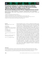
• Synchronous machines (PMSMs): The PMSM owes its origin to the replacement of the exciter of the wound synchronous machine with permanent magnets. These machines have a uniformly rotating stator field as in induction
machines. The stator is fed with 3-phase sinusoidal shaped currents. All
phase windings conduct current at a time with phase differences.
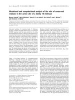
• Brushless DC machines(BLDC): The BLDC owes its origin to an attempt
to invert the brushed DC machine to remove the need for the commutator
and brush gear. Rectangular-shaped phase currents are applied to the stator.
1
2
The field excitation in the rotor is provided in the form of permanent magnet
excitation. Only two phase windings out of three conduct current at any
given instant of time. The structures of PMSM and BLDC are shown in
Figs. 1.1 and 1.2.
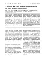
• Brushed DC machines (PMDC): The construction of a PMDC commutator
machine is similar to a conventional DC machine with the electromagnetic
excitation system replaced by permanent magnets. A PMDC commutator
motor can be compared with a separately excited DC motor. The only difference is in the excitation flux in the air gap: for PMDC commutator motor
excitation flux is constant whilst a separately excited DC motor’s excitation
flux can be controlled. The structures of a conventional DC machine and a
PMDC commutator machine are shown in Fig. 1.3.
Figure 1.1: Typical Configurations of PMSM Machine
3
Figure 1.2: Typical Configurations of BLDC Machine
(a)
(b)
Figure 1.3: Typical Configurations of (a) A DC Machine (b) A PM DC Machine
1.2
Permanent Magnet Materials
The most distinguishing part of a permanent magnet machine is that the permanent
magnet is placed inside to provide the field excitation. The design, performance
and application of a permanent magnet machine are closely related to the characteristics of permanent magnet materials. The basic operational characteristic of
a magnet material is the portion of its hysteresis loop in the second quadrant. It
is also called the demagnetization curve. Fig. 1.4 illustrated the basic magnetic
4
properties of permanent magnets.
Figure 1.4: Demagnetization curve and energy product of permanent magnets
When a permanent magnet has been magnetized, it remains magnetized even
if the applied magnetic field intensity is decreased to zero. The magnetic flux density at this point is called the remanence flux density, Br . If a reverse magnetic
field intensity is applied, the flux density decreases. If the value of the reverse
magnetic field is large enough, the flux density eventually becomes zero. The field
intensity value at this point is called the magnetic coercive force or coercivity, Hc .
When the reverse field intensity is removed, the flux density recovers according to
a minor hysteresis loop. Reapplying a reverse field intensity again reduces the flux
density to the original value thus completing the hysteresis loop. The hysteresis
loop is usually a very narrow loop so that it can be approximated by a straight
line called recoil line. The gradient of this line is called recoil permeability, µr . It
is this permeability that determines the change in flux density if the external field
5
changes according to µr = ∆B/∆H. The operating point of a permanent magnet
is the intersection point of a B-H curve of the external magnetic circuit (load line)
and the demagnetisation curve of a permanent magnet. The operation point moves
along the demagnetisation curve with changes in the outer magnetic circuit. The
absolute value of the product of the flux density B and the field intensity H at
each point along the demagnetization curve can be represented by the energy product and this quantity is one of the indexes of the strength of the permanent magnet.
The characteristics of permanent magnet materials vary with the structure
and processing of the materials. The most common type of magnets used in
permanent magnet machines are Alnico, ferrites, samarium-cobalt (SmCo) and
neodymium-iron-boron (NdFeB), their typical characteristic demagnetization curves
are shown in Fig. 1.5.
Figure 1.5: Characteristics of Permanent Magnet Materials