High k dielectric MIM capacitors for silicon RF and analog applications
Bạn đang xem bản rút gọn của tài liệu. Xem và tải ngay bản đầy đủ của tài liệu tại đây (2.34 MB, 154 trang )
High-κ Dielectric MIM Capacitors
for Silicon RF and Analog Applications
HU HANG
(M. Sc., Jilin University)
A thesis submitted in partial fulfillment of the requirements for
the degree of Doctor of Philosophy
Electrical and Computer Engineering Department
National University of Singapore
Singapore
December, 2003
Abstract
ABSTRACT
Metal-insulator-metal (MIM) capacitors in silicon integrated circuits have
attracted great attention due to their high conductive electrodes and low parasitic
capacitance. The conventional MIM capacitors using SiO
2
and Si
3
N
4
usually provide
low capacitance density, which is far from the requirement predicted by ITRS
roadmap. Therefore, to adopt high-κ materials is an unavoidable choice to improve the
overall electrical performance by using physically thicker dielectric films.
In this thesis, a thorough research has been done for high-κ MIM capacitors
using HfO
2
based dielectrics for the first time. Various fabrication methods such as
pulsed-laser deposition, sputtering, and atomic-layer-deposition have been employed
to prepare high-κ dielectrics, and different dielectric structures like laminate, stack,
sandwich, etc, have also been explored as well.
Extensive electrical characterization was conducted to evaluate HfO
2
based
high-κ MIM capacitors. DC properties in terms of leakage, voltage coefficients,
reliability etc, have been analyzed which are strongly correlated to the preparation
methods and material properties. In addition, well behaved RF characteristics of these
dielectrics have been demonstrated showing the almost invariable dielectric constants
of HfO
2
based dielectrics in RF regime. As a result, all the experimental results justify
the suitability of HfO
2
based dielectrics for MIM capacitors application.
Mechanisms with regard to the electronic conduction in high-κ dielectrics,
voltage coefficients of capacitance (VCCs) dependency, oxide degradation etc., have
been discussed and clarified. A good understanding of process-structure-property
I
Abstract
correlation is thus been achieved for high-κ dielectrics fabrication in back-end of line
process, and the information obtained in this thesis is paramount for the operation of
MIM capacitor devices.
Finally, a free carrier injection model has been employed to understand VCCs’
mechanism of MIM capacitors. The results reveal that, the thickness (t) dependence of
quadratic VCCs is an intrinsic problem due to electrical field enhancement in the
scaled dielectric film, which exhibits a relation of
(n~2). Besides, the frequency
dependence of VCCs, and the stress modified VCCs could also been well interpreted
using this model.
n
t
−
∝
α
II
Table of Contents
III
TABLE OF CONTENTS
Page No.
CHPATER 1
INTRODUCTION OF HIGH-Κ MIM TECHNOLOGY
1.1. Capacitors in Si technology……………………… ………………………… 1
1.2. Review of the literature……………………………………………………… 4
1.2.1. Motivation of metal-insulator-metal (MIM) technology……………………….4
1.2.2. Current status of MIM technology…………………………………………… 5
1.2.3. High-κ dielectrics for MIM capacitors application…………………………….7
1.2.4. Challenges and unsolved problems………………………………………… 12
1.3. Contribution of this thesis…………………………………………………….12
1.4. Thesis outline………………….……………………………………………….13
References…………………………………………………………………………….15
CHAPTER 2
HFO
2
MIM CAPACITORS BY PULSED-LASER DEPOSITION (PLD)
2.1. Introduction……………… ………………………………………………….22
2.2. Experiments………………………………………………………………… 24
2.3. Results and discussion………………………………………………………25
2.3.1. Physical characterization of PLD processed HfO
2…………………………………………
25
2.3.2. Electrical characterization of HfO
2
MIM capacitor………………………….35
2.4. Limitations of PLD for thin film fabrication………………………………….43
Table of Contents
IV
2.5. Conclusion……………………………………………………………….……46
References…………………………………………………………………………….48
CHAPTER 3
CHARACTERIZATION OF HFO
2
MIM CAPACITORS FOR RF
APPLICATION
3.1. Introduction………………………………………………………………… 53
3.2. Experiments………………………………………………………………… 54
3.2.1. RF MIM capacitor fabrication………………………………………………54
3.2.2. S-parameters for RF characterization…………………………………………57
3.3. Results and discussion………………………………………………………58
3.3.1. RF characterization……………………………………………………………58
3.3.2. DC and low frequency measurements…… …………………………………63
3.4. Conclusion…………………………………………………………………….70
References…………………………………………………………………………….72
CHAPTER 4
HFALO
X
MIM CAPACITORS BY ATOMIC-LAYER-DEPOSITION (ALD)
4.1. Introduction………………………………………………………………… 76
4.1.1. ALD method for thin films fabrication………………………………………76
4.1.2. Characteristics of ALD processed HfO
2
and Al
2
O
3
………………………… 77
4.2. Experiments………………………………………………………………… 80
4.3. Electrical characterization of HfO
2
-Al
2
O
3
laminated MIM capacitors………81
4.3.1. RF characteristics of laminated MIM capacitors….…………………………82
4.3.2. Leakage and breakdown characteristics of laminated MIM capacitors………84
Table of Contents
V
4.3.3. VCCs dependence and reliability of laminated MIM capacitors……………93
4.4. Effects of dielectric structures on the electrical properties………………….100
4.5. Conclusion………………………………………………………………… 105
Reference…………………………………………………………………………….106
CHPATER 5
UNDERSTANDING VOLTAGE COEFFICIENTS OF HIGH-Κ MIM
CAPACITORS
5.1. Introduction………………………………………………………………….112
5.2. Theory……………………………………………………………………… 113
5.3. Results and discussion……………………………………………………….115
5.3.1. Thickness dependence of VCCs for HfO
2
MIM capacitor………………… 115
5.3.2. Frequency dependence of VCCs………………………………………… 123
5.3.3. Electrical stress modified VCCs…………………………………………… 125
5.3.4. Prediction of VCCs………………………………………………………… 126
5.4. Conclusion……………………………………………………………… …129
References………………………………………………………………………….130
CHAPTER 6
Summary and future works………………………………………………………134
6.1. Summary…………………………………………………………………… 134
6.2. Future works…………………………………………………………………135
List of Figures
VI
LIST OF FIGURES
Figure 1.1 Dielectric constant κ versus band gap for oxides………………… ….8
Figure 2.1 Experimental configuration of pulsed-laser deposition system in this
work………………………………………………………………… 23
Figure 2.2 XRD patterns of HfO
2
thin films deposited on Si(100) substrates at
various substrate temperatures……………………………………… 26
Figure 2.3 Deposition rates of HfO
2
thin films deposited on Si substrates at various
substrate temperatures……………………………………………… 27
Figure 2.4 Three dimensional AFM images of HfO
2
thin films deposited on Si
substrates at various substrate temperatures of (a). 25, (b). 200, (c). 300,
and (d). 500
o
C respectively………………………………………… 28
Figure 2.5 Spectral dependence of refractive indexes of HfO
2
films deposited at (a)
various substrate temperatures (oxygen pressure: 50 mTorr) and (b)
various deposition pressures (all deposited at room temperature)……32
Figure 2.6 Spectral dependence of extinction coefficients of HfO
2
films deposited
at (a) various substrate temperatures (oxygen pressure: 50 mTorr) and
(b) various deposition pressures (all deposited at room temperature) 34
Figure 2.7 TEM photos of 56 nm HfO
2
MIM capacitor fabricated at 200
o
C…….36
Figure 2.8 Current-voltage characteristic of HfO
2
MIM capacitors prepared at 200,
300, and 400
o
C respectively………………………………………… 37
Figure 2.9 Capacitance versus frequency at zero bias for HfO
2
MIM capacitors
prepared at 200, 300, and 400
o
C respectively……………………… 38
List of Figures
VII
Figure 2.10 Normalized capacitance of HfO
2
MIM capacitors prepared at (a) 200, (b)
300, and (c) 400
o
C as a function of voltage applied at a frequency of 1
kHz, 10 kHz, 100 kHz, and 1 MHz respectively………………………39
Figure 2.11 Normalized capacitance of HfO
2
MIM capacitor prepared at 200
o
C as a
function of temperature………………… ………………………… 42
Figure 2.12 SEM top views of HfO
2
film surfaces prepared with the laser fluence of
(a) 4.0 and (b) 7.0 J/cm
2
respectively (fabricated at room
temperature)………………………………………………………… 44
Figure 3.1 Major fabrication steps and schematic top views of RF HfO
2
MIM
capacitor and open dummy structure………………………………….56
Figure 3.2 The definition of S-parameters for a two-port network……………….57
Figure 3.3 The equivalent circuit model for capacitor simulation at RF regime…59
Figure 3.4 The measured and simulated S-parameters for (a) HfO-1 and (b) HfO-2.
(Simulation and parameter extractions were done by ICCAP.)………60
Figure 3.5 High frequency response of PVD HfO
2
MIM capacitors from 50 MHz
to 20 GHz for HfO-1 and HfO-2…………………………………… 62
Figure 3.6 The frequency dependence of capacitance density for PVD HfO
2
MIM
capacitors HfO-1 and HfO-2…………………………………………62
Figure 3.7 Stress induced leakage currents (SILCs) characteristics of (a) HfO-1
and (b) HfO-2 under the constant voltage stress at 1.5 V…………….64
Figure 3.8 Stress time dependence of (a) the quadratic voltage coefficients and (b)
the linear voltage coefficients for HfO-1 under the constant voltage
stress at 1.5 V…………………………………………………………66
List of Figures
VIII
Figure 3.9 Stress time dependence of (a) the quadratic voltage coefficients and (b)
the linear voltage coefficients for HfO-2 under the constant voltage
stress at 1.5 V…………………………………………………………68
Figure 3.10 The equivalent circuit for HfO
2
MIM capacitors after stress. The added
branch stands for the generated trapped states in MIM capacitor after
stress………………………………………………………………… 69
Figure 4.1 The growth rates dependence on deposition cycles for ALD processed
(a) HfO
2
and (b) Al
2
O
3
………………………………………………79
Figure 4.2 TEM cross section of 13 nm HfO
2
-Al
2
O
3
laminated dielectric……….81
Figure 4.3 Measured and simulated S-parameters for (a) 13 nm, (b) 31 nm and (c)
43 nm laminated MIM capacitors……………………………………83
Figure 4.4 The capacitance density dependence on frequency for laminate
capacitors with three thicknesses, the inset shows high frequency
response of laminate MIM capacitors from 50 MHz to 20 GHz…… 84
Figure 4.5 J-V characteristics of 13, 31 and 43 nm laminated capacitors measured
at 125
o
C.…………………………… ……………………………….85
Figure 4.6 J-V characteristics of 13 nm laminated MIM capacitor as a function of
temperature…………………………… …………………………….85
Figure 4.7 Conduction mechanisms for the 13 nm laminated MIM capacitor: (a)
Poole-Frenkel mechanism occurring at high electric field, exhibiting a
shift to lower electric field with increasing the temperature, (b)
Schottky emission fitting at low electric field…………… ………….87
Figure 4.8 The characteristics of leakage current versus stress time under 4V stress
for the 13 nm laminated MIM capacitor. Square and round symbols
List of Figures
IX
represent the 1st stress and the 2nd stress after an interruption of 10
hours, respectively………………………………… ……………….90
Figure 4.9 I-V measurements showing the hysteresis loop of 13 nm laminated
MIM capacitor…………………………………… ………………90
Figure 4.10 (a) The typical breakdown characteristics of 13 nm laminate under
different constant voltage stress; (b) the cumulative probability
dependence on breakdown voltage for the laminated MIM capacitors
with different thicknesses… …………………………………………92
Figure 4.11 (a) The voltage-dependent normalized capacitance (∆C/C
0
) at 1 MHz
for 13, 31 and 43 nm laminated capacitors, fitted by a second order
polynomial equation; and (b) the corresponding plot of ∆C/C
0
versus
electric field (E)………………………… ………………………… 94
Figure 4.12 Frequency dependences of
α
for 13, 31 and 43 nm laminated capacitors,
showing a linear fitting in log-log scale…………… ……………….95
Figure 4.13 Thickness dependence of quadratic VCC (α) for laminated MIM
capacitors.…………………………………………………………… 95
Figure 4.14 Temperature dependences of
α
and
β
at 100 kHz for 13, 31 and 43 nm
laminated capacitors…………………………………………… … 96
Figure 4.15 The dependence of α/α
0
on stress time at 10 kHz, 100 kHz and 1 MHz.
The inset shows stress time dependence of β/β
0
at the same frequencies.
α
0
and β
0
represent the data before voltage stress (β
0
is of negative
sign.), α and β denote the data after different time stress…………….97
Figure 4.16 (a) Cumulative TDDB curves under various constant voltages stress for
13 nm laminated MIM capacitor measured at room temperature, (b)
List of Figures
X
lifetime projection of 13 nm laminated MIM capacitor, using 50%
failure time as the criteria……………… …… …… ……………99
Figure 4.17 Illustrations of five different HfO
2
-Al
2
O
3
material structures for
electrical characteristics comparison……… ……………………….101
Figure 4.18 Typical J-V characteristics for MIM capacitors with different dielectric
structures at 125
o
C. The inset shows the corresponding breakdown
characteristics obtained at the same temperature. (Device area: 10
-4
µm
2
)……………………… ……………………………………….101
Figure 4.19 TEM photos of (a) 13 nm HfO
2
-Al
2
O
3
laminate, (b) 10 nm HfO
2
and
(3) 30 nm HfO
2
films, illustrating the amorphous structure of laminate
film and improved crystallinity with the increase of HfO
2
thicknesses………………………………………………………… 102
Figure 4.20 Evolution of C
0
at zero DC bias with stress time, illustrating the highest
stability for the laminated capacitor compared to other dielectric
structures…………………….……………………………………….104
Figure 5.1 Schottky plot of 30 nm HfO
2
MIM capacitor. The inset shows the
typical J-V curve…………………………………………………… 116
Figure 5.2 Measured and simulated normalized capacitance as a function of
voltage. n
0
and µ are extracted by fitting the measured data.…… …117
Figure 5.3 Carrier concentration pre-factor (n
0
) dependence on thickness…… 118
Figure 5.4 Simulated normalized capacitance as a function of voltage for different
thickness of 20, 30, 40, 50, and 60 nm………… ………………… 119
Figure 5.5 The simulated VCCs as a function of thickness with and without taking
account of the change of pre-factor (n
0
) with thickness……….…….120
List of Figures
XI
Figure 5.6 Linear voltage coefficients versus the capacitance density for HfO
2
based high-κ dielectrics at 100 kHz…………… ………………… 121
Figure 5.7 Normalized capacitance versus DC bias measured at 100 kHz, showing
good symmetrical CV characteristics (small linear coefficients β) for
sandwich and laminate structures……………………………………122
Figure 5.8 The measured VCCs for 30 nm HfO
2
MIM capacitor together with the
extracted carrier mobility at frequencies of 10k, 100k, 500k, 1
MHz……………………………………………………………….…124
Figure 5.9 Simulated normalized capacitance as a function of voltage for 30 nm
HfO
2
MIM capacitors at frequencies of 10k, 100k, 500k, and
1MHz……………………………………………………………… 124
Figure 5.10 (a) The simulated VCCs of HfO
2
MIM capacitors as a function of
thickness with different carrier concentration pre-factor (n
0
), and (b) the
simulated VCCs as a function of thickness with different carrier
mobility in dielectric film…………………………… …………….127
List of Tables
XII
LIST OF TABLES
Table 1.1 Mixed-signal capacitor technology requirements ― Short-term… ….2
Table 1.2 Mixed-signal capacitor technology requirements ― Long-term …….2
Table 1.3 Integration of MIM capacitors into Al BEOL ― Current status… …6
Table 1.4 Integration of MIM capacitors into Cu BEOL ― Current status… 6
Table 2.1 The ratios of SIMS intensities O/Hf for HfO
2
thin films prepared at
various substrate temperatures (oxygen pressure: 50 mTorr)…… …30
Table 2.2 The ratios of SIMS intensities O/Hf for HfO
2
thin films prepared at
various oxygen pressures (All samples are prepared at room
temperature 25
o
C.)………………………………………………… 30
Table 2.3 Voltage linearity coefficients as a function of frequency for HfO
2
MIM
capacitors prepared at 200, 300, and 400
o
C respectively…………… 41
Table 4.1 ALD process conditions for the deposition of HfO
2
and Al
2
O
3
…… 77
Table 4.2 Variations of VCCs and leakage current under different condition
(frequency: 100 kHz; stress voltage: 4V; area: 1×10
-4
cm
-2
)…………98
Table 4.3 Comparison of various high capacitance density MIM capacitors using
high-κ dielectrics (year 2002-2003)…………………………………100
Table 5.1 Different structural HfO
2
-Al
2
O
3
high-κ MIM capacitors prepared by
ALD method…………………………………………… ……… …122
Acknowledgments
XIII
ACKNOWLEDGMENTS
I would like to take this opportunity to express my gratitude to all the people
who make it possible to complete this thesis work.
First and foremost, I would like to give my great thanks to my principle
supervisor, Dr. Zhu Chunxiang, who provides me with an interesting project, constant
direction, valuable advice, and most of all, for providing me with opportunity. He has
my tremendous appreciation and respect.
I am deeply indebted to my co-supervisors, Dr. Lu Yongfeng currently in
University of Nebraska Lincoln and Dr. Subhash Chander Rustagi from Institute of
Microelectronics, Singapore, for being a constant source of help and advice; I truly
appreciate the time, support and encouragement they have given me during the course
of my PhD study.
I owe most thanks to Prof. Li Ming-Fu, A/P Cho Byung Jin, A/P Yoo Won
Jong, Prof. Albert Chin from National Chiao Tung University, Taiwan, and Prof. Lee-
Dim Kwong from UT at Austin, for their always available helping hands, many great
conversations. My special thanks go to Dr. Ding Shi-Jin, I feel privileged to have had
the opportunity to work with him during my time in the PhD program, lots of
collaboration work and fruitful discussions contribute to my thesis development.
I would like to thank my peers with Silicon Nano Device Laboratory in
alphabetical sequence: Chen Jingde, Chen Jinghao, Chen Xiaoyu, Joo Moon Sig, Kim
Sun Jung, Loh Wei Yip, Park Chang Seo, Poon Chyiu Hyia, Debora, Ren Chi, Tan
Kian Ming, Wang Yingqian, Wu Nan, Yang Tian, Yeo Chia Ching, Yu Xiongfei, and
Acknowledgments
XIV
Zhang Qingchun. I have benefited the collaboration work with them, and their
friendship makes my stay in NUS more enjoyable.
Last, and certainly the most, I would like to thank my parents for their love and
support. I can never forget their inspiration and encouragement during my education
years, their constant love and support made the long hours and frustrations bearable.
Chapter 1 Introduction of High-κ MIM Technology
1
Chapter 1
Introduction of High-κ MIM Technology
1.1. Capacitors in Si technology
Basic passive devices including capacitor, inductor, and resistor are
indispensable elements in Si integrated circuits (ICs). Intuitively, passive devices can
only consume or store energy, where active device like metal-oxide-semiconductor
field effect transistor (MOSFET) can also provide amplification. A precise definition
of passive elements was given by Desoer et. al [1]. Given a one-port with port voltage
)(tv and port current )(ti , the one-port is said to be passive if
∫
≥+
t
t
tdttitv
0
0)(')'()'(
0
ε
(1.1)
where )(
0
t
ε
is the energy stored by the one-port at time
0
t . Similarly, with the aid of
the scattering matrix usually used for high frequency measurement, one could also
deduce that the definition of passivity implies
10 ≤≤
ij
S (1.2) [2].
Compared to active devices such as MOSFET in the ultra large scale integrated
circuit (ULSI) technology, passive devices played a relatively minor role. However,
the recent advances in wired and wireless communication trigger demands for high
quality passive devices for radio frequency (RF) and mixed signal applications, and
Chapter 1 Introduction of High-κ MIM Technology
2
therefore spawned a revival interest in passive devices. A good introduction of passive
component technology could be found elsewhere given by R. K. Ulrich [3].
Among the basic passive devices, capacitor is one of the essential elements,
which may find its wide applications in RF circuits for oscillators and phase-shift
networks, in various configurations of analog ICs such as the converters and filters,
and decoupling capacitance in microprocessor units (MPUs), and so on.
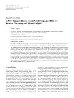
Table 1.1 Mixed-signal capacitor technology requirements ― Short-term [4]
Year of Production 2001 2002 2003 2004 2005 2006 2007
Density (fF/µm
2
) 2 3 3 3 4 4 4
Q (1/KQ
2
•/µm
2
•GHz) 200 300 300 300 450 450 450
Voltage linearity
(ppm/V
2
)
100
100 100 100 100 100 100
Leakage (fA[pF•V]) 7 7 7 7 7 7 7
Analog capacitor
3 σ Matching (%•µm
2
) 4.5 3 3 3 2.5 2.5 2.5
Density (fF/µm
2
) 7 7.5 8 9 10 11 12
Q (1/KQ
2
•/µm
2
•GHz) 22 25 25 29 30 30 30
RF bypass
capacitor
Voltage linearity
(ppm/V)
1000
1000 1000 1000 1000 1000 1000
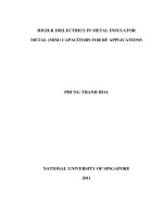
Table 1.2 Mixed-signal capacitor technology requirements ― Long-term [4]
Year of Production 2010 2013 2016
Density (fF/µm
2
) 7 10 15
Q (1/KQ
2
•/µm
2
•GHz) 700 1000 1500
Voltage linearity
(ppm/V
2
)
100 100 100
Leakage (fA[pF•V]) 7 7 7
Analog capacitor
3 σ Matching (%•µm
2
) 2 1.5 1
Density (fF/µm
2
) 17 20 23
Q (1/KQ
2
•/µm
2
•GHz) 35 40 40
RF bypass
capacitor
Voltage linearity
(ppm/V)
1000 1000 1000
Manufacturable Solutions Exist, and Are Being Optimized
Manufacturable Solutions are Known
Manufacturable Solutions are Not Known
Based on the international technology roadmap for semiconductors (ITRS
roadmap) [4], the main requirements and specifications for capacitors are summarized
Chapter 1 Introduction of High-κ MIM Technology
3
in Table 1.1 and Table 1.2, where aggressive projections have been extent to year 2016
with ever increasing performance requirements.
According to Table 1.1 and 1.2, capacitors are categorized into analog and RF
bypass capacitors by ITRS roadmap, and it is believed that the requirements of analog
capacitor are more difficult to be achieved compared to RF bypass capacitor. Here, we
may detail generally the above technique specifications as follows:
1.
Capacitance density
One of the main issues for capacitors is to increase the capacitance per unit
area in order to improve the integration level and reduce the system cost.
2.
Leakage current
The requirement of low leakage is obvious. However, it may be relaxed to
some extent at very high clock frequency [4].
3.
Quality (Q) factor
Q factor is a measure for parasitic effects including the distributed resistance
and inductance, which could be computed by
)(/)(
CapCap
ZrealZimagQ
=
[5]
4.
Voltage coefficients of capacitance (VCCs)
VCC can be approximated by C(V) = C
0
(αV
2
+βV+1) [6],
where C
0
is the capacitance at zero volt and α, β are the quadratic and linear
voltage coefficients of the capacitance respectively.
5.
Temperature coefficients of capacitance (TCCs)
TCC can be usually defined as:
Cppm
dT
dC
T
TCC
o
/
10
6
= [3, 7]
6. Compatibility to back end of line (BEOL) integration
Chapter 1 Introduction of High-κ MIM Technology
4
The capacitors’ fabrication needs to be compatible to existing ULSI backend
technology. Thus, high quality dielectric must be formed at a very low
temperature of ~400
o
C limited by backend process.
1.2. Review of the literature
1.2.1. Motivation of metal-insulator-metal (MIM) technology
Traditionally, metal-insulator-silicon (MIS) [8, 9] structure has been used in Si
ICs. However, this structure was replaced by polysilicon-oxide-polysilicon (double-
poly) capacitor since the electrical performance of double-poly structure was superior
in terms of small VCCs and stray capacitance [10], where the capacitors’ precision is
paramount for those of applications such as A/D converter. Accordingly, double-poly
structure was established as a mature analog component. In addition, the improved
capacitor structures like metal-ploy have also been reported [11, 12].
Though the polysilicon structure could be tailored in many ways to yield good
electrical properties making it suitable for many analog applications, it suffered from
limited RF capability in multi-GHz range [13]. The limitations in the quality factor are
primarily due to the large resistive loss from the electrodes, and the parasitic
capacitance because of the proximity to the lossy silicon substrate [14]. Therefore,
metal-insulator-metal (MIM) structures have been proposed as the next generation
capacitor structure due to their high conductive electrodes and low parasitic
capacitances. In addition, the intrinsic depletion free MIM structures would provide
better voltage linearity property [15].
Chapter 1 Introduction of High-κ MIM Technology
5
Except the applications in Si ULSI circuits, MIM capacitor is also a key
element in GaAs based monolithic microwave integrated circuits (MMICs) [16, 17]. In
addition, the above mentioned problems are also anticipated by dynamic random
access memories (DRAM) that use MIS structure as the charge storage cell. Therefore,
advanced DRAM cell with MIM structures have also been studied [18, 19, 20]. It is
possible to implement MIM for DRAM application beyond the 90 nm node in 2004,
according to ITRS roadmap [4]. In this work, our focus is on high-κ MIM capacitors
integrated into BEOL process for Si RF and analog applications, which is much
different with the requirements of MIM capacitors in MMICs and DRAM cells in
terms of materials, structures, process flow, and other aspects.
1.2.2. Current status of MIM technology
As an emerging technology, MIM capacitors draw great attentions among
semiconductor industry companies in the very recent years. Based on the literature
survey, we summarize the reported MIM capacitors technology from several major
semiconductor companies, which are presented in Table 1.3 and Table 1.4 for Al and
Cu BEOL integration respectively. As can be seen, SiO
2
and Si
3
N
4
are usually chosen
as the dielectric materials for MIM capacitors fabrication in the current technology
node. In comparison, Si
3
N
4
has a higher dielectric constant (κ) of 7 compared to SiO
2
(~3.9), which usually provides relatively higher capacitance density than SiO
2
MIM
capacitors. In addition, Si
3
N
4
could also be used to serve as a good Cu diffusion barrier
[21], therefore eliminating Cu barrier metal stacks usually required in Cu BEOL
process [21, 22]. However, the frequency dependence of capacitance and voltage
linearity for Si
3
N
4
capacitors may degrade the capacitors’ accuracy, which was
Chapter 1 Introduction of High-κ MIM Technology
6
proposed to be originated from bulk traps in nitride films [23]. Low temperature
deposited Si
3
N
4
was reported to show higher relaxation recovery voltage than oxide
[24]. When compared to LPCVD SiO
2
, the breakdown field strength of Si
3
N
4
is lower,
and both its voltage and temperature coefficients are usually higher. Therefore,
schemes such as nitrous oxide plasma treatment [25], silicon oxynitride [26], SiO
2
-
Si
3
N
4
stacks [27] have also been explored to combine the merits of SiO
2
and Si
3
N
4
.
Though SiO
2
and Si
3
N
4
MIM capacitors with excellent electrical performance have
been successfully demonstrated in Al and Cu BEOL process; the capacitance density is
still low, usually ≤ 2 fF/µm
2
.
Table 1.3 Integration of MIM capacitors into Al BEOL ― Current status
Conexant system [15] IBM [28] Toshiba [29]
Dielectric
PECVD Nitride
(30~60 nm)
Single/multi layers
(SiO
2
/Si
3
N
4
, 50-125 nm)
(Ta
2
O
5
, 50 nm)
(Si
3
N
4
, 50 nm)
Bottom electrode Ti/TiN/AlCu/Ti/TiN TiN/AlCu/TiN WSi
2
C (fF/µm
2
)
1.0-1.9 for
30-60 nm thick film
0.44-1.40
4.36
1.01
Leakage
(A/cm
2
)
~1E-10 A/mm
2
for 50
nm Ta
2
O
5
Remark
Life time: 10
6
and 10
3
years for 60 and 30 nm
films.Q >80 at 2 GHz
T
50
> 10
-7
hours, phase
improved by 2× compared
with MOS
Good leakage property
obtained after 300
o
C
furnace annealing
Table 1.4 Integration of MIM capacitors into Cu BEOL ― Current status
Lucent [21] IBM [22] Motorola [30] TSMC [31]
Dielectric Si
3
N
4
(30 nm) SiO
2
(48 nm) Si
3
N
4
(40 nm) Si
3
N
4
Bottom plate Direct on Cu
A conductive
metal stack
Sputtering-TaN
C (fF/µm
2
) 0.72 1.6 1
VCC (ppm/V) 150 TTC= -40 ppm/
o
C <15
VCC= 60 ppm/V
TCC= 50 ppm/
o
C
Leakage
(A/cm
2
)
10
-10
at 5V 10
-6
A at 30 V 10
-10
at 5V
Leakage on
temperature
Weak (25-200
o
C) Weak (25-125
o
C)
E
BD
(MV/cm) 10 10 9-10
TDDB
T
50
>1000 pwr-on-
hrs
Beyong 10 years
Remarks
Si
3
N
4
as both
dielectric and
diffusion barrier
Leakage
sensitivity to T
ox
Q
2GHz
= 30-200
at 3-0.1 pf
Q=100 (2.4 GHz)
and 40 (5.3 GHz)
at 1.1 pf
Chapter 1 Introduction of High-κ MIM Technology
7
Furthermore, it was noted that these of SiO
2
and Si
3
N
4
works are focused on
the integration of MIM capacitors, and the process related issues have thus been well
addressed. Planar structures were usually implemented for MIM capacitors integrated
in BEOL process, and positioning the capacitors beneath the final metal level could
further minimize the loss to the substrate. At or below 0.18 µm technology, Cu
metallization is used instead of Al metallization due to copper’s low resistivity and
feasibility of thick and fine pattern through damascene process [4]. However the
introduction of Cu interconnects will create unique challenges for fabricating high
reliability MIM capacitors, such as surface roughness of Cu on the reliability of MIM
capacitors [21], the proper choice of Cu barrier metal stack [22], and the compatibility
of capacitor dielectric with inter-level dielectric [22], etc.
1.2.3. High-κ dielectrics for MIM capacitors application
As described above, SiO
2
and Si
3
N
4
are dielectrics that are commonly used in
conventional MIM capacitors [6-31]. Although these SiO
2
and Si
3
N
4
MIM capacitors
could provide excellent electrical properties, their capacitance densities are limited due
to their low dielectric constants (κ~3.9 for SiO
2
, κ~7 for Si
3
N
4
). This is far from the
requirement on capacitance density projected by the 2002 ITRS roadmap [4].
Further reduction in dielectric thicknesses of SiO
2
and Si
3
N
4
can increase the
capacitance density, but it may offset leakage current, breakdown voltage, and voltage
linearity property [22, 29]. For instance, it was reported that a 30-nm-thick SiO
2
MIM
capacitor has a voltage linearity of ~ 20 ppm/V
2
[27]. From the 1/t
2
(t: thickness)
dependence [32], the voltage linearity of 14-nm-thick SiO
2
MIM capacitor is supposed
Chapter 1 Introduction of High-κ MIM Technology
8
to reach an upper limit of 100 ppm/V
2
according to ITRS roadmap [4]. However, the
capacitance density of 2.5 fF/µm
2
is low.
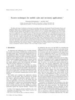
Figure 1.1: Dielectric constant κ versus band gap for oxides [34].
Therefore, the adoption of high-κ materials is imperative to meet the
requirements of MIM capacitors in Si RF and analog IC applications. This is because
of the fact that using physical thicker high-κ dielectric films may potentially improve
the overall electrical performance. In the search to find suitable high-κ dielectrics,
Figure 1.1 presents a compilation of a few potential high-κ dielectric candidates
indicating the relationship of dielectric constant versus band gap. This provides a
simple criterion of selecting suitable high-κ materials as the dielectrics for MIM
capacitors. It is important to note that the general band gap reduction with the increase
of κ value for dielectrics is a limitation that must be considered when selecting a
Chapter 1 Introduction of High-κ MIM Technology
9
suitable high-κ material for MIM capacitor application [33, 34]. The decrease in band
gap is usually coupled with the reduction of breakdown voltage for the dielectric
materials [35].
Among various high-κ candidates for MIM capacitors application, Ta
2
O
5
,
Al
2
O
3
, and HfO
2
high-κ dielectrics are of great interests among researchers due to their
relatively good materials properties and industry’s familiarity.
Ta
2
O
5
based high-κ dielectrics have drawn a great attention, which may be
inspired by memory capacitor applications and the resultant semiconductor
manufacturing tool infrastructure [18, 36]. T. Yoshitomi et. al demonstrated pure
Ta
2
O
5
MIM capacitors by reactive sputtering [29]. With an O
2
annealing at 300
o
C, the
Ta
2
O
5
MIM capacitor exhibit superior electrical performance when compared to its
Si
3
N
4
counterpart at the same equivalent oxide thickness (EOT) in terms of leakage
property. T. Ishikawa et. al integrated Ta
2
O
5
MIM capacitors into Cu BEOL process,
and insertion of thin Al
2
O
3
layer between Ta
2
O
5.
The bottom electrode was designed to
improve the interface quality and the resulting electrical performance [37]. Y. L. Tu et.
al achieved a very good voltage linearity (25 ppm/V
2
and 13 ppm/V) for 4 fF/µm
2
Ta
2
O
5
MIM capacitor when compared to TaO
x
N
y
, HfO
2
, Al
2
O
3
and Ta
2
O
5
/Al
2
O
3
stacks MIM capacitors in their work [38]. However, the electrical properties of those
Ta
2
O
5
MIM capacitors have been reported to be strongly dependent on the fabrication
methods and the following thermal treatments [36, 38]. Therefore, a good
understanding of process-structure-property correlation is of great importance before
selecting Ta
2
O
5
thin films for MIM capacitors application.
Compared with other high-κ candidates, Al
2
O
3
has a moderate dielectric
constant of ~9, making it to be only a short term solution for industry’ need. However,
the low oxygen diffusivity of Al
2
O
3
[34, 39] may improve the interface quality by
Chapter 1 Introduction of High-κ MIM Technology
10
reducing the chemical reaction with metal electrode. A large band gap of 8.9 eV is also
beneficial for the improvement of leakage and breakdown characteristics. For MIM
capacitors application, Al
2
O
3
based high-κ materials including pure Al
2
O
3
[39]
,
Ti
doped Al
2
O
3
[39], and Ta doped Al
2
O
3
[40, 41] have been investigated using an
evaporation/oxidation method, and a high capacitance density of 17 fF/µm
2
has been
achieved for AlTaO
x
MIM capacitor [41]. In particular, the RF performance of high-κ
MIM capacitors have been studied for Al
2
O
3
based dielectrics up to 20 GHz. A
mathematical method was recently proposed for the computation of VCCs in RF
regime for Al
2
O
3
based dielectrics [40]. However, the low thermal budget in the
fabrication of those Al
2
O
3
based high-κ materials is probably responsible for their
marginal electrical performance.
HfO
2
has the advantages of high dielectric constant (~25), high heat of
formation (271 Kcal/mol), and large band gap (5.68 eV), etc. [34]. Most important of
all, HfO
2
based high-κ materials are well established as the next generation gate
dielectric in MOSFETs [42] and DRAM [20]. HfO
2
MIM capacitor was first reported
using a pulsed-laser deposition (PLD) method [43]. Following that, other fabrication
techniques including PVD [44], atomic-layer deposition (ALD) [45] have also been
demonstrated. These techniques are more favourable for the mass production
compared to PLD method. In addition, materials engineering of HfO
2
dielectric such
as Tb doping [44], Al alloying [45], and novel structures of HfO
2
-Al
2
O
3
laminate [46]
and stacks [47] have been further explored to improve the leakage and voltage linearity
properties of HfO
2
MIM capacitors. In summary, compared to the reported Ta
2
O
5
and
Al
2
O
3
MIM capacitors, HfO
2
based high-κ MIM capacitors exhibited nearly the best
overall electrical properties, indicating that they are very promising for the next
generation MIM capacitors application.