Mixed mode i II III fracture criterion and its application to cement mortar 4
Bạn đang xem bản rút gọn của tài liệu. Xem và tải ngay bản đầy đủ của tài liệu tại đây (605.59 KB, 21 trang )
114
4.4 Mixed Mode I – II – III Fracture Testing
4.4.1 Geometry of Specimen
Unlike other mixed mode fracture tests, mixed mode I–II–III fracture tests are
rarely found in the literature. This could be due to the complexity of its specimen
geometry and loading configuration. According to the literature review of foregoing
§1.1.2.4, three different geometries of test specimen have been designed for fracture
under mixed mode I–II–III loading. The experimental set-up proposed by Richard and
Kuna (1990) was designed for plexiglas and aluminium specimens. However, the
loading device would be too clumsy to handle if it were adapted to cement mortar
specimens, since the size of latter would have to be much larger than those of the
former. The specimen designed by Arslan et al (1991) had four failure surfaces in
different zones. However, it would be difficult to control the test in such a way that all
the individual failure surfaces would occur simultaneously, which would be a
requirement of the numerical modelling. The axisymmetric bar-type specimen of Hyde
and Aksogan (1994) is more suited for metal testing and, therefore, not considered in
this application.
Furthermore, in spite of the fact that all three stress intensity factors, K
I0
, K
II0
and K
III0
, were induced at the specimen crack tip under mixed mode I–II–III loading,
none of the abovementioned test set-ups actually achieved a true mixed mode I–II–III
fracture, since the specimens were of uniform thickness, whereas, according to the
unified model (Lo et al., 1996a), mixed mode loading does not necessarily lead to
115
mixed mode fracture, unless an artifice is provided for weakening the potential fracture
plane.
In view of the preceding considerations, a novel geometry of the cement
mortar specimen was designed for the present study of mixed mode I–II–III fracture,
which would be easy to prepare and simple to load. Using the conventional notched
beam specimen for conventional mixed mode I-II fracture testing as the basis, a
modified beam specimen with an inclined groove ligament was found, from an
analytical study, to be optimal in the sense that all the three modes of deformation
could be effectively applied at the crack front. Accordingly, instead of having a vertical
notch, the adopted specimen would have a groove, which was rotated vertically, as
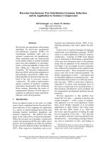
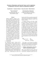
well as horizontally, with respect to the beam section. Figure 4.30 illustrates the final
design of the beam specimen. The overall dimensions of the specimen were 500mm
(length) × 100mm (depth) × 80mm (width). A 2mm-wide groove which was rotated,
both vertically through an angle of α and horizontally through an angle of β, was
formed in the specimen, leaving a V-shaped throat segment, so that a true mixed mode
I–II–III fracture would be generated. The ligament was located such that the middle of
the crack front coincided with the centre of the specimen. Two values were chosen for
α and β, namely 26.56° and 45° respectively, which, as indicated by the subsequent
numerical analyses under differing load cases, would give rise to various combination
of mixed mode deformation at crack front, within the practical limit of preparing the
pre-crack plane and groove ligament. Hence, four groups of beam configuration, with
differing combinations of α and β values, were prepared for testing, as listed in Table
4.1.
116
2mm wide groove
Isometric View
100
α
β
500
80
Note: units in mm where not stated
Sectional View
V-shape throat segment
10mm long pre-crack
crack front
groove
20
100
5
0
5
0
Figure 4.30 Geometry of beam specimen of mixed mode I – II – III
fracture test
117
Table 4.1 Angles of inclination of beam groups
Beam Group
A
Beam Group
B
Beam Group
C
Beam Group
C
α
26.65° 45° 45° 26.65°
β
26.65° 26.65° 45° 45°
It is apparent, from Figure 4.30, that the groove segment is inclined
three-dimensionally and has an awkward shape due to the inclination angles α and β.
Therefore, it would be difficult to achieve by cutting, after the specimen had been
cured for 28 days, unlike the cases of the beam and compact tension specimens, for
pure modes I and II, as well as mixed mode I–III, fracture testing, as dealt with in
§4.2.1 and §4.3.1 respectively. Hence, the grooved segment would have to be formed
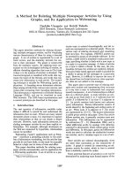
during casting of the specimen. Accordingly, three overlapping stainless steel plates, of
2mm thickness overall, and coated with mould oil, were fixed to the mould before
casting. In order to form the pre-crack face, the centre plate had a deeper embedment,
by 10mm, than the other two, which were geometrically identical (Figure 4.31). To
prevent the plates from getting stuck in the specimen, due to the drying shrinkage of
the cement mortar, the centre-piece was removed within three hours after casting,
while the remaining two pieces were left to prevent the cement mortar from caving in,
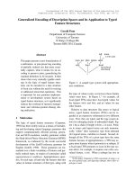
and removed only during de-moulding. Figure 4.32 shows the design of the mould
used to cast the test specimen.
118
cement mortat specimen
pre-crack face
length of
three stainless steel plates
β
Figure 4.31 Formation of groove and pre-crack by three steel plates
119
(a) Mould of test specimen
Figure 4.32 Mould of mixed mode I
−
II
−
III fracture test specimen
(b) Steel plates used to form groove in specimen
120
4.4.2 Laboratory Set-up and Test Procedure
The fracture tests were conducted on an INSTRON 1334 servo-hydraulic
testing machine. In order to achieve differing mode I/mode II and mode I/mode III
loading ratios, each beam group (according to §4.4.1) was subjected to various loading
cases, as depicted in Figure 4.33. In all cases, the specimen was simply-supported. For
cases 1 and 2, the load was applied to the steel I-beam, which distributed the load to
the specimen at two points, in such a way that pure bending and shear would be
obtained at mid-section, under four-point bending and shear, respectively. On the other
hand, in cases 3 and 4, the load was applied directly to the specimen, and a
combination of tensile and shear stresses would, thereby, be produced.
The load was applied monotonically at a rate of 0.1mm/min, until the
specimen failed. The force applied, and corresponding stroke displacement of the
cross-head of the testing machine, were recorded automatically throughout the test.
4.4.3 Determination of Stress Intensity Factors by Finite Element Analysis
Four three-dimensional finite element models, representing the respective
beam groups, were generated using PATRAN Version 8.5 (The MacNeal-Schwendler
Corporation, 1999). Generally, 20-noded, second-order isoparametric, quadratic brick
elements were used in the model. Around the crack front, quarter-point triangular
prismatic elements were used to simulate the strain and stress singularity, as specified
in foregoing §3.1.2. The crack front was modelled by twenty layers of elements. Figure
4.34 shows the overall assembly for beam group A, which consists of 5944 elements
121
500
220
330
500
30
110
30
F
110
F
140
30
F
F
110
500
30
110 110
Steel I-beam
110
30
Steel I-beam
500
110
30
110 110110
30
Note: dimensions are in mm.
(Beam Groups B and C)
(Beam Groups B, C and D)
(Beam Groups A, B and C)
(Beam Groups A and D)
Case 1
Case 2
Case 3
Case 4
Figure 4.33 Loading cases used in mixed mode I–II–III fracture tests
122
groove
V-shaped throat segment
Figure 4.34 Finite element model for beam group A of mixed mode I – II – III fracture test
detailed view
in Figure 4.33
F
F
F
F
123
and 27019 nodes, while Figures 4.35 – 4.36 illustrate the details of the modelling near
the crack front.
Next, numerical analyses were carried out by ABAQUS Version 5.8 (Hibbitt,
Karlsson and Sorensen, Inc., 1998), and the stress intensity factors, K
I0
, K
II0
and K
III0
,
for each layer of elements across the throat, and in each case of unit loading, were
obtained from corresponding nodal displacement at the crack face, according to
equations (3.11), (3.12) and (3.15). The distributions of stress intensity factors along
the crack front were then obtained. Figure 4.37 shows the distributions of stress
intensity factors of each beam group.
4.4.4
Comparison of Analytical and Experimental Results
For each of the beam groups, three specimens were tested under each category
of loading case. Accordingly, thirty beam specimens were tested in all. In every case,
the load was found to rise with stroke displacement of the cross-head of the test
machine, initially. Crack extension started when the load reached its critical value of
F
C
. As illustrated in Figure 4.38, the value of F
C
under four-point shear loading was
significantly higher than those under three- and four-point bending. In the two cases of
bending, the load decreased gradually after
F
C
, until failure occurred in the specimen.
This would imply that additional energy was required to maintain crack extension. In
contrast, in the cases of four-point shear, the peak load dropped suddenly, as the
specimen underwent sudden failure.
The cracks were found to extend along the groove initially, but after a certain
124
crack front
pre-crack face
half groove width element
Figure 4.35 Sectional view showing details of crack front (right half of test specimen)
125
Figure 4.36 Sectional view of twenty layers of quarter-point triangular prismatic elements around crack front
with cut-out view (right half of taest specimen)
crack front
block removed
for cut-off view
twenty layers of
quarter-point elements
126
Note:
For load cases, refer to
Figure 4.31.
-1.0 -0.5 0.0 0.5 1.0
2z/t
-3.0
0.0
3.0
6.0
9.0
12.0
15.0
Stress intensity factor (
×
10
-3
mm
-3/2
)
Load Case 1.
-1.0 -0.5 0.0 0.5 1.0
2z/t
-3.0
0.0
3.0
6.0
9.0
12.0
15.0
Stress intensity factor (
×
10
-3
mm
-3/2
)
Load Case 4.
x
z
crack front
throat segment
K
I0
K
II0
K
III0
t
(a) beam group A
127
-1.0 -0.5 0.0 0.5 1.0
2z/t
0.0
0.2
0.4
0.6
0.8
1.0
Stress intensity factor (
×
10
-3
mm
-3/2
)
Load Case 2.
-1.0 -0.5 0.0 0.5 1.0
2z/t
-10.0
-8.0
-6.0
-4.0
-2.0
0.0
2.0
4.0
Stress intensity factor (
×
10
-3
mm
-3/2
)
Load Case 3.
-1.0 -0.5 0.0 0.5 1.0
2z/t
-10.0
-8.0
-6.0
-4.0
-2.0
0.0
2.0
4.0
Stress intensity factor (
×
10
-3
mm
-3/2
)
Load Case 4.
x
z
crack front
throat segment
K
I0
K
II0
K
III0
t
(b) beam group B
128
-1.0 -0.5 0.0 0.5 1.0
2z/t
0.2
0.4
0.6
0.8
1.0
1.2
Stress intensity factor (
×
10
-3
mm
-3/2
)
Load Case 2.
-1.0 -0.5 0.0 0.5 1.0
2z/t
-4.0
-2.0
0.0
2.0
4.0
6.0
8.0
10.0
Stress intensity factor (
×
10
-3
mm
-3/2
)
Load Case 3.
-1.0 -0.5 0.0 0.5 1.0
2z/t
-2.0
0.0
2.0
4.0
6.0
Stress intensity factor (
×
10
-3
mm
-3/2
)
Load Case 4.
x
z
crack front
throat segment
K
I0
K
II0
K
III0
t
(c) beam group C
129
Figure 4.37 Distributions of stress intensity factors across crack fronts of
various beam groups
-1.0 -0.5 0.0 0.5 1.0
2z/t
-4.0
0.0
4.0
8.0
12.0
16.0
Stress intensity factor (
×
10
-3
mm
-3/2
)
Load Case 1.
-1.0 -0.5 0.0 0.5 1.0
2z/t
-4.0
0.0
4.0
8.0
12.0
Stress intensity factor (
×
10
-3
mm
-3/2
)
Load Case 3.
x
z
crack front
throat segment
K
I0
K
II0
K
III0
t
(d) beam group D
130
Figure 4.38 Typical load-stroke displacement curves for bending and shear
loadings
F
CB3
F
cs
0.0 0.2 0.4 0.6 0.8
Stroke displacement (mm)
0
2
4
6
8
10
12
14
Load (kN)
4-point-bending
F
CB4
shear
3-point-bending
131
stage, deviated from the throat segment to extend vertically upwards (Figure 4.39). The
reason for the deviation was that, as the crack approached the top face of the specimen,
the length of the crack front increased to the extent that the effect of grooving was
insufficient to guide the crack to extend along the throat segment, with the result that
the crack extended along the most critical direction, which was upwards.
The fracture toughness in pure deformation modes I, II and III have been
discussed in foregoing §4.2 and §4.3, as being 0.468MPa
√m, 0.759MPa√m and
1.12MPa
√m, respectively. For each of the mixed mode fracture cases, on the other
hand, K
Iθ
, K
IIθ
and K
IIIθ
(where θ = 0) were evaluated as
C
F
⋅
=
I0Iθ
KK , (4.7)
C
F
⋅
=
II0IIθ
KK (4.8)
and
C
F
⋅
=
III0IIIθ
KK , (4.9)
where K
I0
, K
II0
and K
III0
are the stress intensity factors, due to unit loading, obtained
according to the numerical analysis of the foregoing §4.4.3, and
F
C
the critical load
measured in corresponding laboratory tests, as listed in the appendix of §A.3. The test
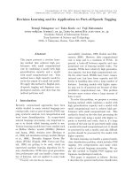
results have been plotted in Figure 4.40, upon which the unified fracture envelope of
preceding equation (2.83), as well as tests results of pure mode fracture tests, have
been superimposed. Accordingly, there is reasonably good agreement between the
unified prediction and experimental results, that is, to within 10%.
132
(b) specimen of beam group B
(a) specimen of beam group A
133
(d) specimen of beam group D
Figure 4.39 Failure of mixed mode I – II – III fracture test specimens
(c) specimen of beam group C
134
Figure 4.40 Comparison of fracture criterion with mixed mode I – II – III
fracture test results
0.0 0.2 0.4 0.6 0.8 1.0
K
I
θ
/ K
IC
0.0
0.2
0.4
0.6
0.8
1.0
√
(K
II
θ
/ K
IIC
)
2
+ (K
III
θ
/ K
IIIC
)
2
K
I
θ
K
IC
( )
2
+
( )
2
+
( )
2
K
II
θ
K
IIC
K
III
θ
K
IIIIC
=1
Test results