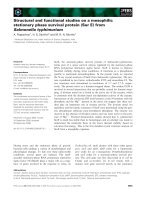
Structural, electrical and optical studies on the effects of rapid thermal processing on silicon germanium carbon films
Bạn đang xem bản rút gọn của tài liệu. Xem và tải ngay bản đầy đủ của tài liệu tại đây (5.5 MB, 242 trang )
STRUCTURAL, ELECTRICAL AND OPTICAL STUDIES ON
THE EFFECTS OF RAPID THERMAL PROCESSING ON
SILICON-GERMANIUM-CARBON FILMS
FENG WEI
NATIONAL UNIVERSITY OF SINGAPORE
2002
STRUCTURAL, ELECTRICAL AND OPTICAL STUDIES ON THE
EFFECTS OF RAPID THERMAL PROCESSING ON SILICON-
GERMANIUM-CARBON FILMS
FENG WEI
(M. Eng, XJTU)
A THESIS SUBMITTED
FOR THE DEGREE OF DOCTOR OF PHILOSOPHY
DEPARTMENT OF ELECTRICAL AND COMPUTER ENGINEERING
NATIONAL UNIVERSITY OF SINGAPORE
2002
Acknowledgements
I would like to express my heartfelt gratitude to Associate Professor Choi Wee Kiong for
his guidance and support in providing me the opportunity to engage in this enriching
academic exercise.
I am grateful to Mr. Walter Lim and Mdm. Luo Ping for their help in the use of Lab
equipment. I would like to especially thank Dr. L. K. Bera for his many invaluable
technical advice and friendship. I would like to think Dr. Ramam, Mr. Liu Rong, Ms. Ji
Rong, Mr. Huang Qingfeng for their help in the XRD, SIMS, Raman and DLTS
measurement. I would like to appreciate al my fellow friends in the Microelectronics Lab.
I would like to thank Professor Carry Yang from Santa Clara University for providing the
epitaxial samples used in this work.
Lastly, I also should thank my parents and sister for their mental support during the three
years.
ii
Table of Contents
Chapter Title Page
Acknowledgements i
Table of Contents ii
Summary v
List of Figures viii
List of Tables xv
1 Introduction 1
1.1 Research background 1
1.2 Research objective 6
1.3 Structure of thesis 8
1.4 References 9
2
Review of Si
1−
−−
−x
Ge
x
and Si
1−
−−
−x−
−−
−y
Ge
x
C
y
alloy
13
2.1 Introduction 13
2.2 Review of strained Si
1-x
Ge
x
alloys 14
2.2.1 Band aligment and electrical properties of strained Si
1-x
Ge
x
system
16
2.2.2 Local structure characterization 19
2.2.3 Oxidation study of Si
1-x
Ge
x
alloys 21
2.2.4 Electrical properties of oxide/ Si
1-x
Ge
x
system 22
2.2.5 Optical transition of Si
1-x
Ge
x
films 24
2.3 Review of strained Si
1-x-y
Ge
x
C
y
alloys 29
2.3.1 Band aligment and electrical properties of strained
Si
1−x−y
Ge
x
C
y
alloys
30
2.3.2 Local bonding structure of Si
1-x-y
Ge
x
C
y
alloys 32
2.3.3 Thermal stability and oxidation of Si
1-x-y
Ge
x
C
y
alloys 38
2.3.3.1 The annealing behavior of Si
1-x-y
Ge
x
C
y
alloys 38
2.3.3.2 Oxidation study of Si
1-x-y
Ge
x
C
y
alloys 39
2.3.4 The optical properties of Si
1-x-y
Ge
x
C
y
films 40
2.4 References 43
3 Theories of Measurement Techniques 54
3.1 High-Resolution X-Ray Diffraction (HRXRD) 54
3.1.1 X-ray diffraction rocking curve 54
3.1.2 Quantitative rocking curve analysis 57
3.2 Electrical Characterization of MOS system 60
3.2.1 C-V characterization of MOS system 60
iii
3.2.2 Deep level transient spectroscopy (DLTS) 71
3.2.2.1 Theory of DLTS in MOS capacitor 72
3.2.2.2 Distinction between interface states and bulk traps 78
3.2.2.3 Limitation of DLTS testing using MOS capacitor 78
3.3 The optical parameter measurement by spectroscopic ellipsometry 79
3.3.1 Determination of optical constant by SE 79
3.3.2 The general features of dielectric function 82
3.3.3 Determination of critical point 86
3.4 References 89
4 Experimental Details 91
4.1 Sample preparation 91
4.1.1 Rapid Thermal Chemical Vapor Deposition (RTCVD) 93
4.1.2 Rapid Thermal Processing (RTP) 94
4.1.3 The fabrication process of MOS capacitor 98
4.2 Structural Characterization 99
4.2.1 High-Resolution X-Ray Diffraction (HRXRD) 99
4.2.2 Raman Spectroscopy 100
4.2.3 Fourier Transform Infrared Spectroscopy (FTIR) 100
4.2.4 X-Ray Photoelectron Spectroscopy (XPS) 101
4.2.5 Secondary Ion Mass Spectrometry (SIMS) 101
4.2.6 Transmission Electron Microscopy (TEM) 101
4.3 Electrical Characterization 102
4.3.1 Capacitance-Voltage, Conductance-Voltage Measurements 102
4.3.2 Current-Voltage (I-V) characteristic 103
4.3.3 Deep level transient spectroscopy (DLTS) 103
4.4 Optical characterization by Spectroscopic Ellipsometry (SE) 104
5 Structural characterization of as-grown and rapid thermal
processed Si
1−
−−
−x
Ge
x
and Si
1−
−−
−x−
−−
−y
Ge
x
C
y
strained alloys
106
5.1 Structural characterization of as-grown a Si
1−x
Ge
x
and Si
1−x−y
Ge
x
C
y
strained alloys
5.1.1 High resolution X-ray diffraction (HRXRD) 106
5.1.2 Raman spectroscopy 110
5.1.2.1 Raman spectra of strained Si
1−x
Ge
x
alloys
112
5.1.2.2 Raman spectra of Si
1−x−y
Ge
x
C
y
alloys
113
5.1.3 Fourier transform infrared (FTIR) spectroscopy 117
5.2. Structural characterization of rapid thermal processed Si
1−x
Ge
x
and
Si
1−x−y
Ge
x
C
y
strained alloys
119
5.2.1 Effect of RTO and RTA on strain and C configuration of
Si
1−x−y
Ge
x
C
y
alloys
120
5.2.1.1 Strain change and loss of substitutional C 120
5.2.1.2 C configuration from IR results 130
5.2.1.3 C and Ge element depth profile from SIMS 136
5.2.1.4 Observation of SiC precipitation from TEM 141
5.2.2 Interface properties of SiO
2
/Si
1−x−y
Ge
x
C
y
system
143
5.2.2.1 XPS results of as-grown Si
1−x−y
Ge
x
C
y
samples
143
iv
5.2.2.2 Oxide/ Si
1−x−y
Ge
x
C
y
interface
145
5.3 Summary 148
5.4 Reference 149
6
Electrical characterization of rapid thermal oxides on Si
1−
−−
−x
Ge
x
and
Si
1−
−−
−x−
−−
−y
Ge
x
C
y
alloys
154
6.1 Electrical characterization of oxides grown at 1000°C
154
6.1.1 High frequency C-V characteristics 154
6.1.2 Effect of C related defect on oxide/epi-layer interface
properties
162
6.1.3 Current-voltage characteristics of oxides on Si
1−x
Ge
x
and
Si
1−x−y
Ge
x
C
y
alloys
183
6.1.4 Constant current stressing 186
6.2 Electrical results of 800°C grown rapid thermal oxides
188
6.2.1 Capacitance-voltage characteristics 189
7.2.2 Current-voltage characteristics 193
6.3 Summary 194
6.4 References 196
7
Spectroscopic ellipsometry characterization of as−
−−
−grown and
rapid thermal oxidized Si
1−
−−
−x
Ge
x
and Si
1−
−−
−x−
−−
−y
Ge
x
C
y
alloys
200
7.1 Dielectric function of as-grown Si
1-x
Ge
x
and Si
1-x-y
Ge
x
C
y
alloys 202
7.2 Dielectric function of rapid thermal oxidized Si
1−x
Ge
x
and
Si
1−x−y
Ge
x
C
y
alloy
206
7.3 Spectroscopic Ellipsometry results of RTO substrates 210
7.4 Summary 215
7.5 References 217
8 Conclusions and Recommendations 219
8.1 Conclusions 219
8.2 Recommendations 222
Appendix Publications 224
Summary
The benefits of band structure engineering, as well as compatibility with standard
silicon (Si) technology, make fabrication and characterization of Si-based group IV alloy
intensive research activities. The effect of rapid thermal processing (annealing and
oxidation) on the structural, electrical and optical properties of strained Si
1−x
Ge
x
and
Si
1−x−y
Ge
x
C
y
alloys is the main concern of this thesis.
Various kinds of structural characterization techniques such as XRD, FTIR, TEM,
XPS, SIMS and Raman spectroscopy were performed on as-prepared and rapid thermal
processed Si
1−x−y
Ge
x
C
y
alloys. For the as-grown sample, incorporating substitutional carbon
(C) into the Si
1-x
Ge
x
system can either partially, fully or over compensate the compressive
strain in the layers. The substitutional C is not stabilized when the processing temperature
is higher than 900°C. The substitutional C can change to the more stable β-SiC phase as
well as out diffuse as CO or CO
2
(oxidation case). The loss of substitutional carbon is
responsible for the strain change of a thermally processed sample. Similar to the oxidation
of Si
1−x
Ge
x
, the direct oxidation of Si
1−x−y
Ge
x
C
y
alloy also leads to germanium (Ge) pileup
at the oxide/epi-layer interface.
Electrical characterization of rapid thermal oxides grown at different temperatures
(1000°C and 800°C) on Si, Si
1-x
Ge
x
and Si
1-x-y
Ge
x
C
y
alloy has been carried out on MOS
capacitors. The C-V measurements of oxides grown at 1000°C revealed that the interface
state density increased from 3×10
11
to 3×10
12
/cm
2
eV with the C concentration increasing
from 0 to 1.84%.The observed negative fixed charge density ranged around 1.5×10
11
to
2.0×10
11
/cm
2
. This confirms the Ge pileup also happen at the interface/epi-layer interface
v
in SiGeC system. Compared to oxide on Si
1-x
Ge
x
, high temperature oxidation of
Si
1−x−y
Ge
x
C
y
sample generated the C-related defect that can be electrical activated at high
temperature, which lead to the quite high effective doping concentration.
Oxides grown at 800°C showed the interface density was in the range of
10
12
/cm
2
eV for Si
1-x
Ge
x
and Si
1-x-y
Ge
x
C
y
samples. Compared with oxidation at 1000°C, a
proper low temperature oxidation recipe can prevent the huge doping concentration in the
Si
1−x−y
Ge
x
C
y
sample. I-V characteristic of oxides grown at two different oxidation
temperatures showed a better insulating property of the oxide grown at 1000°C. The high-
field conduction mechanism of oxide grown at 1000°C followed the normal Fowler-
Nordheim tunneling. The barrier height of tunneling and electrical breakdown field
decreased with C concentration, which implied a rougher interface. The charge-to-
breakdown (Q
bd
) also reduced as C amount increases, which infer that C outdiffusion is
related to the formation of trap and conductive path in oxide.
The optical properties of as-grown and rapid thermal oxidised Si
1−x
Ge
x
and
Si
1−x−y
Ge
x
C
y
films were characterized by spectroscopic ellipsometry (SE). The reduction of
transition peak amplitudes with increase of C concentration is due to the alloying effect and
stoichiometric deformation of the films. The detailed lineshape analysis results revealed
that C incorporation shifted the E
1
transition to higher energy at a rate of 42mV/[C]%. The
boarding factor also increased from 0.137eV to 0.197eV as C concentration varied from 0
to 1.84%. After RTO, the top oxide layer, with thickness comparable to optical beam
penetration depth, was the main cause for the different measurement results (the bi-layer
assumption used in SE measurement is no longer valid). Compared with the as-grown
sample, the lower energy of E
1
transition position and increase of refractive index (n) in the
vi
RTO substrate (with oxide etched away) were mainly attributed to the Ge pileup at the
interface, which was in agreement with structural analysis. The dependence of E
1
position
on the C amount was no longer valid after oxidation, which confirmed the C loss observed
in previous structural analysis.
vii
List of Figures
Figure Description Page
Fig. 1.1 The integrated silicon chip of the future. CMOS, HBT/bipolar, SiGe
quantum devices, SiGe detectors, SiGe waveguides and a light
emitter all on the one chip
1
Fig. 1.2 Si BJT and SiGe HBT band diagram
2
Fig. 1.3 (a) A fully pseudomorphic pMOS layer configuration with typical
design parameters. (b) The quantum well for holes and inversion of
the strained SiGe layer under a surface Si
4
Fig. 1.4 Device structures for n-MOSFETs fabricated on (a) strained
Si/relaxed Si
0.8
Ge
0.2
and (b) unstrained Si (“epi Si control”). In-situ
doped boron profiles and thin Si
0.8
Ge
0.2
boron diffusion barriers were
designed such that the doping profiles below the gate were well
matched for the two structures after device processing
5
Fig. 1.5 Effective mobility as a function of effective electric field. Under an
electric field of up to ~1.5 MV/cm, mobility in the strained-Si devices
increased by 120% and 42% for electrons and holes, respectively,
over the universal mobility
5
Fig. 2.1
The growth of strained or relaxed Si
1−x
Ge
x
alloys on Si substrate
15
Fig. 2.2 The critical thickness as a function of Ge concentration for various
growth temperatures
16
Fig. 2.3 Band offset of (a) strained SiGe layer on unstrained Si substrate and
(b) strained Si layer on unstrained SiGe virtual substrate
17
Fig. 2.4 Energy band structure of a 2DEG in a tensile strained Si
18
Fig. 2.5 The first order Raman spectra of Si
0.67
Ge
0.33
layer grown on Si (001)
20
Fig. 2.6 Real (a) and imaginary (b) parts of the pseudo-dielectric function
<ε
1
>+i<ε
2
> for the Si
x
Ge
1−x
alloys
26
Fig. 2.7 The dependence of transition energies for bulk Si
1-x
Ge
x
alloys
27
Fig. 2.8
Plot of the E
1
and E
1
+∆
1
band gaps of relaxed Si
1−x
Ge
x
/Si and the
29
viii
estimated band gaps of strained layer using Eq. (2.11)-(2.15)
Fig. 2.9 Valence-band offsets for compressive strained Si
1-x
Ge
x
and
Si
1−x−y
Ge
x
C
y
(x=10%, 20%, and 30%, y varied between 0% and 3%)
and tensile strained Si
1-y
Cy and Si
1-x-y
Ge
x
C
y
(y=1%, 2%, and 3%, x
varied between 0% and 30%) plotted as a function of the effective
lattice mismatch expressed in ‘‘effective’’ Ge or C concentrations,
respectively
31
Fig. 2.10 Summary of valence band offsets extracted from MOS capacitance-
voltage (C–V) characteristics for p-type Si/Si
1-x-y
Ge
x
C
y
capacitors.
The offset is extracted by fitting C–V simulations to the measured
data
32
Fig. 2.11 Room temperature mobility (a) and hole density (b) of pure Si (solid
square) and two sample sequences: The First sequence (open squares)
starts with Si
0.94
Ge
0.06
. By adding carbon, while leaving the
germanium content constant, the strain is subsequently reduced until
strain relaxation is reached (Si
0.935
Ge
0.006
C
0.0055
) then the amount of
germanium is reduced leading equally to Si
0.995
C
0.0053
. The second
sequence starts with Si
0.96
Ge
0.04
and ends with Si
0.996
C
0.004
.
33
Fig. 2.12 Temperature dependence of the hole mobility for the compressively
strained Si
0.94
Ge
0.06
, exact strain compensated Si
0.935
Ge
0.06
C
0.055
and
tensile strained Si
0.995
C
0.055
layers
34
Fig. 3.1 Single-crystal diffractometer with sample “rocked” to obtain a XRD
rocking curve
55
Fig. 3.2 Schematics of the (a) simple single-crystal diffractometer, (b) double-
crystal diffractometer and (c) five-crystal diffractometer
56
Fig. 3.3 Tetragonal distortion of strained epilayer to match substrate
57
Fig. 3.4 Typical rocking curve of an epi-layer on a substrate
59
Fig. 3.5 MOS schematic with charges associated with the oxidized Si
61
Fig. 3.6 The effect of fixed oxide charge on the shift of C-V curve. Solid line
for ideal curve, dash line for sample with negative fixed charge
61
Fig. 3.7 The effect of interface trap on high frequency C-V characteristics of
MOS system (left) and band structure of gate material and Si
substrate (right)
63
Fig. 3.8 Energy distribution of interface state within the Si bandgap
64
ix
Fig. 3.9 Low-frequency equivalent circuit of MOS capacitor (left) and high
and low frequency C-V characteristics (right)
65
Fig. 3.10 Determination of surface potential from C-V characteristics
67
Fig. 3.11 C-V and C-t behaviors of an MOS capacitor pulsed into deep
depletion
68
Fig. 3.12 (a) C-t response and (b) Zebrbst plot
69
Fig. 3.13 Sequence of the bias voltage (a), resulting capacitance transient (b),
and energy band bending and electron occupancy of interface states
and bulk traps in an MOS capacitor with an n-type substrate in the
steady state with a quiescent bias V
a
(1), in the capture process with a
bias V
b
(2), and in the emission process with the bias V
a
(3)
73
Fig. 3.14 Schematic diagram of an ellipsometer. P and S denote polarizations
parallel or perpendicular to the plane of incidence, respectively
81
Fig. 3.15 Band structure and major interband transition in the Silicon and
Germanium
84
Fig. 3.16 A comparison of the theoretical and experimental dielectric function
curves for Si. (a) for real part (b) for imaginary part
85
Fig. 3.17 A comparison for the imaginary part of the dielectric function in Ge
85
Fig. 4.1 Layer structure of Si
1-x
Ge
x
or Si
1-x-y
Ge
x
C
y
/Si samples used in this
work
92
Fig. 4.2 Schematic diagram of the rapid thermal processing system
95
Fig. 4.3 Temperature-time profile of the rapid thermal oxidation process used
in this work
96
Fig. 4.4 The fabrication process flow of MOS capacitor
98
Fig. 5.1 (004) X-ray rocking curves of Si
0.887-y
Ge
0.113
C
y
and Si
0.8-y
Ge
0.2
C
y
alloys grown by rapid thermal chemical vapor deposition
107
Fig. 5.2
A typical Raman spectrum of Si
1−x−y
Ge
x
C
y
alloy. The peak of Si-Si
(substrate) was omitted to enhance Si-Ge, Ge-Ge, Si-C vibration
modes
111
Fig. 5.3 Typical room temperature Raman spectrum of Si
0.9911
Ge
0.113
C
0.0059
sample. The dashed lines are the individual components that
correspond to the Si-Si vibrations of the substrate and that of the alloy
112
x
layer
Fig. 5.4 The Ge concentration dependence of Si-Si, Si-Ge vibration modes in
strained and relaxed Si
1−x
Ge
x
alloys. The solid and dot lines are fitting
curves for strained and relaxed alloys. The scattering dots are
experimental results of two sets of strained and relaxed films
113
Fig. 5.5
Peak positions of the Si-Si Raman line of as-grown Si
0.887−y
Ge
0.113
C
y
and Si
0.8−y
Ge
0.2
C
y
samples relative to the Raman line of pure Si as a
function of carbon concentration (y)
114
Fig. 5.6 A typical Raman difference spectrum between Si
0.887
Ge
0.113
and
Si
0.887−y
Ge
0.113
C
y
centered around the Si-C mode
116
Fig. 5.7 Shift of the Si-C Raman peak in Si
0.883-y
Ge
0.113
C
y
as a function of the
C concentration
117
Fig. 5.8 Infrared absorption spectra of Si
0.887
Ge
0.113
and Si
0.887-y
Ge
0.113
C
y
samples
118
Fig. 5.9 Infrared absorption spectra of Si
0.8
Ge
0.2
and Si
0.8-y
Ge
0.2
C
y
samples
118
Fig. 5.10 (004) X-ray rocking curves of rapid thermal oxidized
Si
0.887−y
Ge
0.113
C
y
and Si
0.8-y
Ge
0.2
C
y
alloys
122
Fig. 5.11 Peak positions of the Si-Si Raman lines of as-prepared and oxidized
Si
0.887−y
Ge
0.113
C
y
and Si
0.8−y
Ge
0.2
C
y
samples relative to the Raman line
of pure Si as a function of carbon concentration (y)
124
Fig. 5.12 (004) x-ray rocking curves of as-grown and rapid thermal annealed
Si
0.8811
Ge
0.113
C
0.0059
alloys (a) and Si
0.8767
Ge
0.113
C
0.0103
alloys (b)
127
128
Fig. 5.13 The substitutional C amount calculated from XRD results versus
annealing temperature
129
Fig. 5.14 The change of FWHM of XRD peaks for Si
0.8827
Ge
0.113
C
0.0043
(a) and
Si
0.8767
Ge
0.113
C
0.0103
(b) alloys RTA at different temperatures. A
similar result for Si
0.89
Ge
0.11
/Si heterostructure is also included for a
comparison purpose
129
Fig. 5.15 Infrared absorption spectra of rapid thermal oxidized
Si
0.887−y
Ge
0.113
C
y
alloys
131
Fig. 5.16 Infrared results of as-grown and rapid thermal annealed
Si
0.8811
Ge
0.113
C
0.0059
(a) and Si
0.8767
Ge
0.113
C
0.0103
alloys (b)
133
134
xi
Fig. 5.17 Integrated density of Si-C peaks in FTIR results versus annealing
temperature
135
Fig. 5.18 Raman spectra of as-grown and rapid thermal annealed
Si
0.8767
Ge
0.113
C
0.0103
alloys
136
Fig. 5.19 SIMS profiles of C and Ge for Si
0.8686
Ge
0.113
C
0.0184
sample before and
after rapid thermal oxidation
138
Fig. 5.20 SIMS profiles of C (a) and Ge (b) for as-grown and RTA
Si
0.8767
Ge
0.113
C
0.0103
alloys
140
Fig. 5.21 Cross-sectional TEM image of typical as-grown Si
0.8686
Ge
0.113
C
0.0184
alloy
142
Fig. 5.22 Cross-sectional TEM micrograph of rapid thermal oxidized
Si
0.8686
Ge
0.113
C
0.0184
sample
143
Fig. 5.23
A typical wide scan spectrum of the as-prepared Si
1−x−y
Ge
x
C
y
alloy
144
Fig. 5.24
Typical XPS depth profile of as-prepared Si
1−x−y
Ge
x
C
y
alloy obtained
by Ar ion sputtering
145
Fig. 5.25 Montage of Ge 2p
3/2
of oxidized Si
0.8686
Ge
0.113
C
0.0184
sample
146
Fig. 5.26 Montage of Ge 3d of oxidized Si
0.8686
Ge
0.113
C
0.0184
sample
147
Fig. 5.27 XPS depth profiles of rapid thermal oxidized Si
0.8686
Ge
0.113
C
0.0184
sample
147
Fig. 6.1
The HF-CV characteristics of RTO (1000°C) oxide on top of Si,
Si
0.887
Ge
0.113
and Si
0.887−y
Ge
0.113
C
y
samples
155
Fig. 6.2 The effective doping concentration of Si, Si
0.887
Ge
0.113
and
Si
0.887−y
Ge
0.113
C
y
alloys after RTO at 1000°C
158
Fig. 6.3 Quasi-static and high frequency (1MHz) C-V characteristics of
capacitor fabricated on Si
0.887
Ge
0.113
and Si
0.8811
Ge
0.113
C
0.0059
substrates
163
Fig. 6.4
Interface trap density (D
it
) and capture cross section (σ
n
) of capacitor
fabricated on Si
0.887
Ge
0.113
and Si
0.8811
Ge
0.113
C
0.0059
substrates
164
Fig. 6.5 C-V characteristics of MOS capacitor fabricated on Si, Si
0.887
Ge
0.113
,
and Si
0.887−y
Ge
0.113
C
y
substrates measured at different frequencies
167
xii
Fig. 6.6 Capacitance versus time (C-t) characteristics of MOS capacitor
fabricated on epi-Si, Si
0.887
Ge
0.113
, and Si
0.8811
Ge
0.113
C
0.0059
substrates
170
Fig. 6.7 DLTS spectra of Al-SiO
2
-Si
0.887
Ge
0.113
capacitors at different pulse
heights
172
Fig. 6.8 DLTS spectra of Al-SiO
2
-Si
0.887
Ge
0.113
capacitors at different reverse
biases V
r
173
Fig. 6.9 (a) The DLTS spectra of Al-SiO
2
-Si
0.887
Ge
0.113
capacitor at different
scanning window rates (b) Arrhenius plot of ln(e
n
/T
2
) vs 1/T
174
Fig. 6.10 The C-V (1MHz) curves of (a) Al-SiO
2
-Si
0.887
Ge
0.113
(b) Al-SiO
2
-
Si
0.8811
Ge
0.113
C
0.0059
capacitor at different temperatures
177
Fig. 6.11 Doping concentrations obtained from the C-V curves of
Al−SiO
2
−Si
0.887
Ge
0.113
and Al−SiO
2
−Si
0.8811
Ge
0.113
C
0.0059
capacitors at
different temperatures
178
Fig. 6.12 HF C-V (a) and G-V (b) characteristics of MOS capacitors fabricated
by PECVD SiO
2
deposited on as-grown and rapid thermal annealed
Si
0.8811
Ge
0.113
C
0.0059
alloys
179
Fig. 6.13 C-V characteristics of MOS capacitors fabricated by PECVD SiO
2
deposited on as-grown (a) and rapid thermal annealed (b)
Si
0.8811
Ge
0.113
C
0.0059
alloys measured at different frequencies
181
Fig. 6.14 Capacitance versus time (C-t) characteristics of MOS capacitors
fabricated by PECVD SiO
2
deposited on as-grown (a) and rapid
thermal annealed (b) Si
0.8811
Ge
0.113
C
0.0059
alloys
182
Fig. 6.15 I-V characteristic of rapid thermal oxidized Si
0.887
Ge
0.113
and
Si
0.887−y
Ge
0.113
C
y
samples
184
Fig. 6.16 The plot of ln(J/E
2
) versus 1/E of rapid thermal oxides grown on
Si
0.887
Ge
0.113
and Si
0.887−y
Ge
0.113
C
y
samples
185
Fig. 6.17 The voltage built up process of constant current stressing for
Si
0.887−y
Ge
0.113
C
y
samples
187
Fig. 6.18
The charge-to-breakdown (Q
bd
)
of rapid thermal oxides on Si
1−x
Ge
x
and Si
1−x−y
Ge
x
C
y
samples
188
Fig. 6.19 High-frequency (1MHz) C-V characteristics of MOS structures with
Si
0.887
Ge
0.113
and Si
0.8811
Ge
0.113
C
0.0059
substrates RTO at 800°C
190
xiii
Fig. 6.20 C-V curves of capacitors fabricated on Si
0.8811
Ge
0.113
C
0.0059
films
oxidized at 800°C in O
2
(a) and N
2
O (b), measured at different
frequencies
192
Fig. 6.21 I-V characteristics of oxides grown on Si
0.887
Ge
0.113
and
Si
0.8811
Ge
0.113
C
0.0059
substrates in N
2
O or O
2
ambient, RTO at 800°C
194
Fig. 7.1 Pseudo-dielectric function vs photon energy for the as-grown
Si
0.887
Ge
0.113
and Si
0.887−y
Ge
0.113
C
y
alloys
201
Fig. 7.2 Second derivatives of the pseudo-dielectric function of as-grown
Si
0.887
Ge
0.113
and Si
0.887−y
Ge
0.113
C
y
alloys
204
Fig. 7.3
Energies of the E
1
and E
0
’
critical points of as-grown Si
0.887−y
Ge
0.113
C
y
alloys as a function of C concentration
205
Fig. 7.4 Imaginary parts of the pseudo-dielectric function of as-grown and
RTO Si
0.887
Ge
0.113
and Si
0.887−y
Ge
0.113
C
y
alloys
208
Fig. 7.5 The penetration depths of Si
0.887
Ge
0.113
and Si
1-0.113-y
Ge
0.113
C
y
alloys
as a function of photon energy
209
Fig. 7.6 Pseudo-dielectric function vs photon energy for RTO Si
0.887
Ge
0.113
and Si
0.887−y
Ge
0.113
C
y
alloys
211
Fig. 7.7 Second derivatives of the pseudo-dielectric function of RTO
Si
0.887
Ge
0.113
and Si
0.887−y
Ge
0.113
C
y
alloys
212
Fig. 7.8 Energies of the E
1
and E
0
’
critical points as a function of C
concentration for the RTO Si
0.887−y
Ge
0.113
C
y
alloys with oxide etched
away
213
Fig. 7.9 Refractive indices of as-grown and RTO Si
0.887
Ge
0.113
and
Si
0.887−y
Ge
0.113
C
y
alloys
215
xiv
List of Tables
Tables Title Page
1.1 1995 prices for different semiconductor materials
2
1.2 (a) SiGe circuit fabricated before 1995, selected SiGe circuit fabricated
recently
3
2.1 Properties of group IV elements and compounds
14
2.2 A carriers’ mobility comparison for different materials structure at
300K
18
4.1 Substrate preparation before Si
1-x
Ge
x
and Si
1-x-y
Ge
x
C
y
alloy film
growth
92
4.2 RTCVD processing parameters for Si
1-x
Ge
x
and Si
1-x-y
Ge
x
C
y
alloy
films used in this work
94
4.3 Samples used in this work that have undergone rapid thermal
processing (RTP), and their respective RTP conditions
97
5.1
The lattice mismatch strain of the as-grown Si
0.887−y
Ge
0.113
C
y
and
Si
0.8−y
Ge
0.2
C
y
alloys calculated from the XRD results. The Ge and C
concentrations of the as-grown samples were estimated using the
Vergard’s law
108
5.2
The lattice mismatch strain of rapid thermal oxidized Si
0.887−y
Ge
0.113
C
y
and Si
0.8−y
Ge
0.2
C
y
alloys calculated from the XRD results
121
6.1 The shift of flat band voltage, fixed charge density and doping
concentration of Si
0.887−y
Ge
0.113
C
y
samples
160
6.2
The interface state density of Si
0.887−y
Ge
0.113
C
y
samples
161
6.3 The breakdown electric field and barrier potential height of
Si
0.887−y
Ge
0.113
C
y
samples
186
6.4 Oxide thickness, conductivity, breakdown field, and interface density
of RTO oxides grown at 800°C and doping concentration on
Si
0.887
Ge
0.113
and Si
0.8811
Ge
0.113
C
0.0059
alloys. Also included here for
comparison are the oxide thickness, conductivity, breakdown field, and
interface state density of RTO oxides grown at 1000°C in O
2
on the
190
xv
same substrates.
7.1 Critical point position and broadening factor used in the lineshape
analysis of second derivative of pseudo-dielectric function of as-
prepared Si
0.887
Ge
0.113
and Si
1-0.113-y
Ge
0.113
C
y
alloys
203
7.2 Critical point position and broadening factor used in the lineshape
analysis of second derivative of pseudo-dielectric function of oxidized
Si
0.887
Ge
0.113
and Si
1-0.113-y
Ge
0.113
C
y
alloys
210
xvi
1
Chapter 1 Introduction
1.1 Research Background
Over the four decades, the development of microelectronics has been dominated
by Silicon-based technology [1]. The rapid development of epitaxial technology
successfully provided the high quality strained silicon-germanium (Si
1−x
Ge
x
)
film on Si
substrate about ten years ago, which opens a new era of Si-based band-gap engineering
[2]. Figure 1.1 shows the potential SiGe system integrated with matured Si CMOS
technology [3].
Fig. 1.1 The integrated silicon chip of the future. CMOS, HBT/bipolar, SiGe quantum devices, SiGe
detectors, SiGe waveguides and a light emitter all on the one chip[3].
The easiest transistor to integrate with CMOS is SiGe heterojunction bipolar
transistor (HBT). The smaller bandgap of SiGe, dominate valence band offset in
Si/SiGe system as well as graded Ge profile base (shown in Fig. 1.2) make Si/SiGe/Si
n-p-n HBT transistor much superior than homojunction Si bipolar junction transistor
(BJT)[4]. It offers three key three advantages: 1) a reduction in base transit time result
2
in higher frequency performance (e.g. f
T
, f
max
), 2) an increase in collect current density
and hence current gain with low intrinsic base resistance, and 3) an increase in Early
voltage at a given cutoff frequency. Compared to III-IV compound semiconductor, the
material cost of SiGe technology is much promising (Tab. 1.1). SiGe Microsystems Inc.
believes that the major cost addition in SiGe BiCMOS technology come from epitaxy
only adds 15% to the total cost. Research devices with f
T
up to 120 GHz [5] and f
max
up
to 150 GHz [6] have been demonstrated although BiCMOS integrated processes for
production show more modest values of around 50-60 GHz [7]. Numerous
commercialized applications of SiGe HBT are already available, a summary of
selectived circuits and their performance are given in Tab. 1.2 [8].
Fig. 1.2 Si BJT and SiGe HBT band diagram [4]
Table 1.1 1995 prices for different semiconductor materials [3]
3
Table 1.2 (a) SiGe circuit fabricated before 1995, selected SiGe circuit fabricated recently
[8]
The application of SiGe strained layer in MOSFET is still in development stage.
There are two major types of MOSFET configurations [9].
1). Strained SiGe p-MOSFETThe smaller mobility of hole than electron
make pMOS transistor about 2 to 3 times larger than nMOS transistor in CMOS
circuit. The ability to match p-channel device to nMOS would be of significant
benefit to CMOS performance. A strained SiGe channel grown below the gate oxide
(Fig 1.3) [10] with a higher hole mobility is an ideal way to achieving this. The
4
highest hole mobility extracted by Voinugescu et al. [11] from this type of
heterojunction MOSFETs was as high as 400 cm
2
/Vs.
Fig. 1.3 (a) A fully pseudomorphic pMOS layer configuration with typical design parameters. (b)
The quantum well for holes and inversion of the strained SiGe layer under a surface Si[10].
2). Strained-Si n-MOSFET and p-MOSFET: The tensile strained Si grown on
relaxed Si
1-x
Ge
x
buffer layer offers both mobility enhancement for electron and hole.
Both n-MOSFET and p-MOSFET are built using this material system. Figure 1.4 [15]
show the device structure of n-MOSFET fabricated on strained Si/relaxed Si
0.8
Ge
0.2
and
Si control sample. The effective mobility at high field enhanced by 75% compared to
the epi Si control device. Surface roughness also plays an important role on mobility
enhancement for both electron and hole. Figure 1.5 [16] shows that CMP buffer relaxed
Si
1−x
Ge
x
can improve the electron and hole mobility enhancement factor up to 120%
and 42%.
5
Fig. 1.4 Device structures for n-MOSFETs fabricated on (a) strained Si/relaxed Si
0.8
Ge
0.2
and (b)
unstrained Si (“epi Si control”). In-situ doped boron profiles and thin Si
0.8
Ge
0.2
boron diffusion
barriers were designed such that the doping profiles below the gate were well matched for the two
structures after device processing [15].
Fig. 1.5 Effective mobility as a function of effective electric field. Under an electric field of up to
~1.5 MV/cm, mobility in the strained-Si devices increased by 120% and 42% for electrons and
holes, respectively, over the universal mobility[16].
Although Si
1-x
Ge
x
alloys demonstrated various important applications, the
Si
1−x
Ge
x
on Si system has some severe limitations [17]. There is a critical thickness for
perfect pseudomorphic growth. The layer thickness has to be kept below a critical value
6
for free tuning of crystallographic and, therefore, some electronic devices cannot be
made with such a small film thickness. On the other hand, the main band offset between
Si and strain SiGe is located in the valence band. Hence, this system is much better as a
hole channel than as an electron channel.
Recently, the addition of substitutional carbon to Si
1−x
Ge
x
provides a new path
for band structure engineering [17]. Some advantages of adding carbon (C) have been
demonstrated. First of all, photoluminescence (PL) measurement has shown that
substitutional C reduces the strain in Si
1-x
Ge
x
at a faster rate than it increases the band
gap. Thus for a given band gap, it is possible to obtain a more thermally stable film
using Si
1-x-y
Ge
x
C
y
rather than Si
1-x
Ge
x
. Both John [19] and Mocuta [20] demonstrated
Si
1-x-y
Ge
x
C
y
–channel p-MOSFET with improved thermal stability. Another observation
is the suppression B diffusion in Si and SiGe by adding low concentration (less than
0.2%) substitutional C [21]. It provides a wider process margin and flexibility, and
substantially enhances the high frequency performance of SiGe HBT [22]. These
advantages have made the growth and characterization of Si
1−x−y
Ge
x
C
y
an intense
research topic over the last five years.
1.2. Research Objective
It should be mentioned that, however, there are still challenges in the application
of the Si
1−x
Ge
x
/Si system, particularly in the higher Ge fraction system. This comes
from process related problems such as the higher strain and lower equilibrium critical
thickness [23]. The formation of dislocation and strain relaxation has deleterious effects
on the device performance [9].
The growth of a high quality gate oxide is an essential step in the fabrication of
any metal-oxide-semiconductor (MOS) related device [24]. This proves to be somewhat
troublesome in Si
1−x
Ge
x
and Si
1−x−y
Ge
x
C
y
systems. Basically, to avoid strain relaxation
7
and dislocation formation in Si
1−x
Ge
x
and Si
1−x−y
Ge
x
C
y
alloys, only low thermal budget
process should be adopted [25]. However, the device performance requires the high
quality oxide for surface passivation with lower interface state.
Regarding the thermal stability of Si
1−x
Ge
x
and Si
1−x−y
Ge
x
C
y
alloys, considerable
work have been done using conventional thermal process. Rapid thermal processing, as
a low thermal budget technique, is widely used in the manufacturing of advanced
semiconductor devices [26]. For a thin strained layer, a short high temperature process
may be desirable. While some work of rapid thermal oxidation on Si
1−x
Ge
x
have been
reported [27-29], to the best of our knowledge, little work [30, 31] has been reported on
the rapid thermal annealing or oxidation of Si
1−x−y
Ge
x
C
y
film.
Therefore, this study will concern with characterizing the material properties
(structural, electrical, and optical) of as-prepared and rapid thermal processed (oxidation
and annealed) Si
1−x
Ge
x
and Si
1−x−y
Ge
x
C
y
alloys grown by RTCVD.
The structural properties of the as-prepared and rapid thermal oxidized (or
annealed) RTCVD grown Si
1−x
Ge
x
and Si
1−x−y
Ge
x
C
y
films have been investigated using
high resolution X-ray diffraction (HRXRD), Raman spectroscopy, Fourier Transform
Infrared Spectroscopy (FTIR), X-ray photoelectron spectroscopy (XPS), secondary ion
mass spectrometry (SIMS) and Transmission Electron Microscopy (TEM) techniques.
The interface properties of the oxide/epitaxial layers were examined by
capacitance-voltage (C−V), capacitance-time (C−t) measurements and deep level
transient spectroscopy (DLTS) on MOS capacitors. The current-voltage characteristic
and constant current stressing were performed to check the bulk oxide properties.
The optical properties of Si
1−x
Ge
x
and Si
1−x−y
Ge
x
C
y
films were monitored using
spectroscopic ellipsometry (SE).