A preliminary research on development of a fibre composite, curved FDM system
Bạn đang xem bản rút gọn của tài liệu. Xem và tải ngay bản đầy đủ của tài liệu tại đây (2.79 MB, 96 trang )
A PRELIMINARY RESEARCH ON DEVELOPMENT OF
A FIBER-COMPOSITE, CURVED FDM SYSTEM
LIU YUAN
(B. Eng.)
A THESIS SUBMITTED
FOR THE DEGREE OF MASTERS OF ENGINEERING
DEPARTMENT OF MECHANICAL ENGINEERING
NATIONAL UNIVERSITY OF SINGAPORE
2008
Acknowledgements
First and foremost I would like to express my sincere thanks and appreciation to my
supervisor, Associate Professor Ian Gibson, for guidance, for his involvement in this
research, for the technical discussions and particularly for his support throughout the
course of my Master studies. I would not have finished this thesis without his support
and drive
Thanks to my colleague, Dr. Savalani Monica Mahesh, for the suggestion and
discussion with her at the research project. I am also very grateful to research engineer
Anand Nataraj and fellow post-graduate student Muhammad Tarik Arafat for
encourage and discussion in study.
I would also like to thank Advanced Manufacturing Laboratory (AML) and Laboratory
for Concurrent Engineering and Logistics (LCEL) for providing facility to complete
my research.
Last but no least, I would like to express my deep sense of gratitude to my parents, for
the financial and spiritual support and encouraged me throughout this difficult but
exciting journey.
Also, some of this work was funded by the MOE grant “Curved Fused Deposition
Modelling”.
i
Table of Contents
Acknowledgements i
Table of Contents ii
Summary iv
List of Figures v
List of Tables vii
List of Papers viii
Chapter 1 Introduction 1
1.1 Rationale of Rapid Prototyping 2
1.1.1 Stereolithography (SLA) 4
1.1.2 Selective Laser Sintering (SLS) 5
1.1.3 Laminated Object Manufacturing (LOM) 7
1.1.4 Fused Deposition Modeling (FDM) 8
1.1.5 Ink-jet deposition processes (ZCorp 3DP, Solidscape and Objet machines)
10
1.1.6 Ballistic Particle Manufacture (BPM) 13
1.1.7 Metal powder systems 14
1.1.8 Composite materials in RP 15
1.2 Rapid Manufacturing 16
1.2.1 Geometric freedom 17
1.2.2 Materials 17
1.2.3 Elimination of tooling 18
1.3 The objectives of the thesis 18
Chapter 2 Overview of Curved-FDM 21
2.1 Hardware design 24
2.1.1 The basic of screw design 25
2.1.2 Design variables 26
2.2 Material selection 27
2.3 Discussion 33
2.3.1 Benefits 33
ii
2.3.2 Barriers: 34
2.4 Conclusion 35
Chapter 3 Process Parameters 36
3.1 Process variables 37
3.2. Build parameter considerations 38
3.3 Introduction of software 40
3.5. Design of experiment 43
3.4 Experiment setup 45
3.4.1 Materials 45
3.4.2 Extrusion temperature 46
3.4.3 Dispensing speed 47
3.4.4 Envelop temperature 48
3.4.5 Cross hatch 49
3.5 Experiment 49
3.5.1 Preparation of compressive specimens 50
3.5.2 Preparation of tensile specimens 50
3.5.3 Results 52
Chapter 4 3D Curvature 59
Chapter 5 Future Works 65
Chapter 6 Conclusion 69
References 71
Appendices 75
iii
Summary
A novel rapid prototyping technology incorporating a curved layer building style is
being developed. The new process, based on fused deposition modeling (FDM), will
be developed for improving the mechanical properties of layer manufactured structures.
A short fibre reinforced composite is used to improve the mechanical properties of the
FDM objects. A machine was built for efficient fabrication of shell structures using
addition of curved layers. A detailed description will be made of the material
properties and hardware for this new process. The development of the material for
FDM filaments and accompanying process technology for curved layer fabrication will
also be discussed. When making curved layer objects, high performance composites
can improve the mechanical properties of FDM articles since the layers conform to the
part geometry. Extensive experimentation has been done to find out the effect of fiber
content in the filament and to see the effect of fibre orientation and distribution in the
FDM parts.
iv
List of Figures
Figure 1.1 Stereolithography process 5
Figure 1.2 Selective Laser Sintering process 6
Figure 1.3 Laminated Object Manufacturing process 7
Figure 1.4 Fused Deposition Modeling process 9
Figure 1.5 Process of Z Corp 3DP 11
Figure 1.6 process of photopolymer inkjet system 13
Figure 1.7 Ballistic particle manufacturing 13
Figure 2.1 schematic diagram of the Curved-FDM 22
Figure 2.2 Comparative layer-based approach for building parts 24
Figure 2.3 The sketch of extruder screw (James L. White, 2003) 26
Figure 2.4 The engineering drawing of screw 27
Figure 3.1 Curved-FDM 36
Figure 3.2 slice control 41
Figure 3.3 crosshatch setting 41
Figure 3.4 round-way connected toolpath 42
Figure 3.5 3D modeling 43
Figure 3.6 Tensile Strength of different wood fiber contents and coupling agent in
elevated Temperature. (Specimens: Filaments) 47
Figure 3.7 samples with one layer 48
Figure 3.8 the side view of the sample 49
Figure 3.9 2D drawing of the tensile specimen (4mm thickness) 50
Figure 3.10 Long raster and short raster deposition patterns 51
Figure 3.11 Compressive modulus in 1% deformation with different wood fiber and
coupling agent contents 53
v
Figure 3.12 Tensile strength of different wood fibers content and coupling agent in 180
˚C. (Specimens: Dog-bone) 55
Figure 3.13 the SEM pictures of tensile fractured specimens (20%WF 3% MAPP 77%
PP) 56
Figure 3.14 20% WF,3% MAPP,77% PP (Pellet) 57
Figure 3.15 the upper is made of pp, the other is made of wood composite 57
Figure 4.1 Schematic diagram of respectively fabricating curved-FDM parts by using
3- & 5-axis control 61
Figure 4.2 a curved filament which is deposited in x-z plane 62
Figure 4.3 fabricating curved FDM parts with support 63
Figure 4.4 sample with two layers 63
Figure 5.1 the flow chart of sample production and testing 67
vi
List of Tables
Table 2.1 Comparision between Curved-FDM and Stratasys FDM 23
Table 2.2 Comparison of the properties of natural fibres and glass fibre 32
Table 3.1 FDM process variables 37
vii
List of Papers
Published papers:
Liu Yuan and Ian Gibson, A Framework for Development of a Fiber-composite,
Curved FDM System, Proceedings of the International Conference on
Manufacturing Automation, Singapore, 2007
Ian Gibson, Savalani Monica Mahesh, Muhammad Tarik Arafat and Liu Yuan, The
use of multiple materials in Rapid Prototyping, Proceedings of the third international
conference on Advanced Research in Virtual and Rapid Prototyping, Leiria,
Portugal, 2007
Ian Gibson, Liu Yuan and Anand Nataraj,Composites in RP, Proceedings of The
Eighth Annual International Conference on Transportation Weight Reduction,
Pilanesburg, Published by Rapid Prototyping Association of South Africa
(RAPDASA), South Africa, 2007, CDROM version only.
Paper in preparation:
Savalani Monica Mahesh, Liu Yuan, Ian Gibson, Fused Deposition Modeling of Fiber-
composites, Rapid Prototyping Journal, in preparation.
viii
Chapter 1 Introduction
Rapid prototyping is the name given to a group of related technologies that are used to
fabricate physical objects directly from CAD data sources. These methods are unique
in that they can produce objects by stacking materials in layers. Such systems,
according to the unique process, also are named as additive fabrication, solid freeform
fabrication, three dimensional printing and layer manufacturing. Five most common
uses of rapid prototyping are: visualization, form and fit, product test, tooling and end-
use parts(rapid manufacturing, or RM) (Carter,2001). So far RP technologies are
most used by designers and engineers to better understand and communicate the
designs as well as to make rapid tooling to produce those products. People from other
disciplines also use RP technologies such as surgeons, architects, artists, etc. When the
RP material is suitable, highly complicated shapes can be produced because of the
nature of RP and often RP is referred to as providing ‘complexity for free’. In some
cases, the RP part can be the final part, but typically the RP part is not strong or
accurate enough, or some other material property is not suitable for the application
(colour, translucency, thermal transfer, etc.). Presently most of the research work is
directed toward developing new materials or processes which target on mechanical
properties improvement of RP parts (Masood,1996)
1
Chapter 1 Introduction
1.1 Rationale of Rapid Prototyping
Compared to classical subtractive manufacturing methods, the principle of Rapid
Prototyping is totally different and can be summarized as follows:
1) The objects are formed directly from CAD files. A CAD model is constructed and
converted to STL files. Then the STL files are processed to sliced layers by RP machin
-e systems.
2) The first layer of the objects is built by the RP system. Then the platform is lowered
by the thickness of one layer, and the process is repeated until the whole model
finishes.
3) Remove all the supports, post-treat the model.
The above-mentioned unique process results in advantages in many applications
compared to traditional machinery methods, such as milling or turning.
1) Unlock the potential of design. Visually complex geometries can be made without
tooling.
In conventional manufacturing, there is a direct link between the complexity of a part
and its cost. The need for tooling in conventional manufacturing represents one of the
most restrictive factors for today’s product development. The high cost and need for
tooling greatly limits product design and compromises have to be made. In Rapid
prototyping (RP), complexity is independent of cost and RP techniques are able to
produce virtually any geometry. The main benefit to be gained by taking an additive
manufacturing approach (including most, but not all, of the currently available RP
techniques) is the ability to manufacture parts of virtually any complexity of geometry
entirely without the need for tooling. Without the need for tooling, the possibilities for
design are literally only limited by imagination.
2
Chapter 1 Introduction
2) Material flexibility. Multiple materials, composites or functionally gradient
materials can be used in RP systems.
One type of composites’ aims is to reinforce material properties by mixing a dispersed
phase homogeneously within the matrix. Another type of composite is characterized by
having different material characteristics on separate surfaces or in separate parts. As is
the case for any manufacturing process, the choice of materials is in part dependent on
the specifics of the process. In RP, material flexibility does not mean any material
could be used in any specific RP process. The natures of RP (such as layer by layer
building process) make RP to have more potential to use multi materials or composites.
Rapid prototyping technologies are already able to reliably process parts in polymers,
metals and ceramics and the potential for functionally graded components adds a
degree of freedom for a combination of materials that had not previously existed. The
RP composite parts are generally produced using the technique of laser sintering or
laser fusion of powders. Polymer based materials melt and flow in fused deposition
modeling (FDM) and selective laser sintering (SLS). Metal based materials are molten
in the powder spray processes and in direct laser sintering.
3) Rapid prototyping systems reduce the construction of complex objects to a
manageable, straightforward, and relatively fast process.
The advantages of Rapid Manufacturing (RM) lie in the ability to produce highly
complex parts that require no tooling and thus a reduction in the costs of manufacture
will be possible. By using rapid prototyping methodologies, complex geometries with
undercuts and channels can be fabricated in a single part that would normally require
multiple pieces and processes to achieve a similar result. It is easy to envision the
advantages of RP on removing manufacturing constraints on geometric shapes that can
be built.
3
Chapter 1 Introduction
These properties have resulted in their wide use as a way to reduce time to market in
manufacturing. In addition, there is a multitude of experimental RP methodologies
either in development or used by small groups of individuals, including
Stereolithography (SLA), Selective Laser Sintering (SLS), Laminated Object
Manufacturing (LOM), Fused Deposition Modeling (FDM), Ink Jet printing
technologies, Ballistic Particle Manufacture (BPM), etc. Each of the technologies has
its single strength and weakness. A few most used RP technologies are introduced
below.
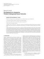
1.1.1 Stereolithography (SLA)
Stereolithography is one of the most widely used rapid prototyping technologies.
Stereolithography builds plastic parts or objects a layer at a time by tracing a laser
beam on the surface of a vat of liquid photopolymer. This class of materials, originally
developed for the printing and packaging industries, quickly solidifies wherever the
laser beam strikes the surface of the liquid. Once one layer is completely traced, it is
lowered a small distance into the vat so that a thin amount of resin now covers the first
layer and a second layer is traced right on top of the first. The self-adhesive property of
the material causes the layers to bond to one another and eventually form a complete,
three-dimensional object after many such layers are formed. The process of SLA is
shown in Fig. 1.1.
Advantages: SLA models have close tolerances and good surface finish. Transparent
models can be built, as can models with some elasticity.
4
Chapter 1 Introduction
Disadvantages: both the machines and materials are expensive. Support structures must
be removed form finished models. A post-curing apparatus is required and material
properties degrade quite quickly.
Figure 1.1 Stereolithography process
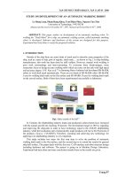
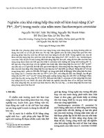
1.1.2 Selective Laser Sintering (SLS)
Thermoplastic powder is spread by a roller over the surface of a build cylinder (Fig.
1.2). The piston in the cylinder moves down one object layer thickness to
accommodate the new layer of powder. The powder delivery system is similar in
function to the build cylinder. Here, a piston moves upward incrementally to supply a
measured quantity of powder for each layer. A laser beam is then traced over the
surface of this tightly compacted powder to selectively melt and bond it to form a layer
of the object. The fabrication chamber is maintained at a temperature just below the
melting point of the powder so that heat from the laser need only elevate the
temperature slightly to cause sintering. This greatly speeds up the process and prevents
5
Chapter 1 Introduction
thermal distortion of the part due to large temperature variations. The process is
repeated until the entire object is fabricated.
Figure 1.2 Selective Laser Sintering process
Advantages: Because the unfused powder provides support, there is no solid support
material to be broken off of the finished part. This reduces material waste and prevents
any compromise in part surface quality. Loose powder can also be used to separate out
interlocking features, thus making it possible to create parts with separate and moving
features. A large variety of materials, polymers, ceramics, and metals, can be used for
building models by coating their powders with resin.
Disadvantages: Machines and materials are expensive. Metal or ceramic parts must be
post-sintered to achieve sufficient strength.
6
Chapter 1 Introduction
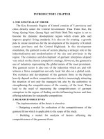
1.1.3 Laminated Object Manufacturing (LOM)
Profiles of object cross sections are cut from paper or other web material using a laser
(Fig. 1.3). Variations of this process may use a blade instead of a laser. The paper is
unwound from a feed roll onto the stack and first bonded to the previous layer using a
heated roller which melts a plastic coating on the bottom side of the paper. The profiles
are then traced by an optics system that is mounted to an X-Y stage. After cutting of
the layer is complete, excess paper is cut away to separate the layer from the web.
Waste paper is wound on a take-up roll. The method is self-supporting for overhangs
and undercuts. Areas of cross sections which are to be removed in the final object are
heavily cross-hatched with the laser to facilitate removal. It can be time consuming to
remove extra material for some geometries, however.
Figure 1.3 Laminated Object Manufacturing process
Advantages: although the basic LOM process is usually described with paper as the
building material, various plastic, fiber glass composite, ceramics and even metals
7
Chapter 1 Introduction
have been successfully used. Ceramic and metal sheets are made from powders which
allow a wide variety of compositions. LOM paper models can be larger than models
produced by most other processes, and paper is probably the least expensive of all
modeling materials.
Disadvantages: removal of support material requires skill and patience to avoid
damage to models. Paper models must be sealed with paint or other coating to be
dimensionally stable, and are generally not suitable for product test or for end use parts.
Ceramic or metal-powder models require careful furnace sintering to achieve usable
strengths.
1.1.4 Fused Deposition Modeling (FDM)
FDM is also a widely used rapid prototyping technology (Fig. 1.4). A plastic filament
is unwound from a coil and supplies material to an extrusion nozzle. The nozzle is
heated to melt the plastic and has a mechanism which allows the flow of the melted
plastic to be turned on and off. The nozzle is mounted to a mechanical stage which can
be moved in both horizontal and vertical directions. As the nozzle is moved over the
table according to the required slice geometry, it deposits a thin bead of extruded
plastic to form each layer. The plastic hardens immediately after being extruded from
the nozzle and bonds to the layer below. The entire system is contained within a
chamber which is held at a temperature just below the melting point of the plastic.
Several materials are available for the process including ABS and investment casting
wax. ABS offers good strength, and more recently polycarbonate and
poly(phenyl)sulfone materials have been introduced which extend the capabilities of
the method further in terms of strength and temperature range. Support structures are
8
Chapter 1 Introduction
fabricated for overhanging geometries and are later removed by breaking them away
from the object. A water-soluble support material which can simply be washed away is
also available.
Advantages: The FDM process can build models from ABS and other plastics which
are light and strong but relatively brittle compared with equivalent injection moulded
plastics. Colored filament is available and a single part can be produced multi-colored.
The use of soluble supports means that interlocking features can be made in a similar
Figure 1.4 Fused Deposition Modeling process
way to SLS, but generally requiring larger clearances. The use of two separate nozzles,
normally for part and support materials, means that different materials can be placed in
a single layer. This makes it possible for a limited type of functional gradient material
application.
Disadvantages: Most shapes require support material which must be broken away,
sometimes causing damage to the model. Water-soluble support material is now
9
Chapter 1 Introduction
available however, although the waste cannot be disposed of in the sewer. The process
is limited to thermoplastic polymers.
1.1.5 Ink-jet deposition processes (ZCorp 3DP, Solidscape and Objet machines)
As the fastest growing rapid prototyping technologies, Ink-jet deposition processes can
be presented by Zcorp 3DP (Fig. 1.5), Solidscape and Objet machines. In terms of
materials, these processes could be separated to 2 categories:
1) Printing of binders (Z Corp 3D printing)
Z Corp 3D printing is similar to the SLS method except instead of using a laser to
sinter material together a print head dispenses a solution to bind the powder together.
The Z Corp systemconsists of the following parts: feed piston, build piston, spreading
apparatus and print head gantry. The feed piston is used to measure and dispense
powder that is spread across the build piston by means of a spreading apparatus. Once
the initial layer is spread, the lowest cross section of the part is printed by spraying a
binder solution on the powder substrate by means of an inkjet print head on the print
head gantry. After the initial layer is printed, the feed piston raises one layer thickness
and the build piston lowers one thickness and the spreader then spreads a layer of
powder over the first cross section. The print heads are then used to print the next layer.
This process continues until the part is completed. Once the part has been completed
and the binder has been allowed to dry sufficiently, the part can be removed and excess
powder can be blown off of the part. Like SLS, no support structures are needed
because the excess powder on the build piston acts as a support during the build. Once
the part is de-powdered, the part can be finished using infiltrates, varying from wax,
cyanoacrylate and epoxy materials, to increase strength and achieve a desirable finish.
10
Chapter 1 Introduction
The Z Corp based 3DP technology allows parts to be built very quickly and
inexpensively. This makes these types of models excellent for visual aids and concept
models. The disadvantages to the technology is that the surface finish, accuracy and
strength are poor compared to some other methods.
Figure 1.5 Process of Z Corp 3DP
2) Printing of materials (Solidscape for wax, Objet for photopolymers)
The Solidscape, Inc.'s inkjet 3D printer uses a single jet each for a plastic build
material and a wax-like support material, which are held in a melted liquid state in
reservoirs. The liquids are fed to individual jetting heads which squirt tiny droplets of
the materials as they are moved in X-Y fashion in the required pattern to form a layer
of the object. The materials harden by rapidly dropping in temperature as they are
deposited.
After an entire layer of the object is formed by jetting, a milling head is passed over
the layer to make it a uniform thickness. Particles are vacuumed away as the milling
head cuts and are captured in a filter. The process is repeated to form the entire object.
11
Chapter 1 Introduction
After the object is completed, the wax support material is either melted or dissolved
away.
The most outstanding characteristic of the Solidscape system is the ability to produce
extremely fine resolution and surface finishes, essentially equivalent to CNC machines.
However, the technique is very slow for large objects. While the size of the machine
and materials are office-friendly, the use of a milling head creates noise which may be
objectionable in an office environment. Materials selection also is very limited.
Objet Geometries Ltd., an Israeli company, introduced its first machine based on
PolyJetTM technology in early 2000 (Fig. 1.6). It's a potentially promising
replacement for stereolithography. The process is based on photopolymers, but uses a
wide area inkjet head to layerwise deposit both build and support materials. It
subsequently completely cures each layer after it is deposited with a UV flood lamp
mounted on the printhead. The support material, which is also a photopolymer, is
removed by washing it away
12
Chapter 1 Introduction
Figure 1.6 process of photopolymer inkjet system
with pressurized water in a secondary operation. With specifications similar to laser-
based stereolithography systems costing several times as much, and operating
conveniences similar to lower-cost 3D printers, this is an important technology to
watch.
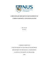
1.1.6 Ballistic Particle Manufacture (BPM)
There is another process which uses ink jets to directly deposit low-melting target
materials. Ballistic Particle Manufacturing (BPM), which was developed and
commercialized by BPM Technology, Inc. (U.S.), uses a piezoelectric jetting system to
deposit microscopic particles of molten thermoplastic (Fig. 1.7). BPM uses 3-D data
about a solid model to position streams of material on a target. 3-D objects are
generated in a way that is comparable to how inkjet printers produce 2D images. Like
FDM and SLA, support structures are required for "unconnected" features. The
supports are deposited in a perforated pattern to facilitate removal. Part material
supports are made from water soluble wax (polyethelene glycol) and are removed after
completion by placing the model in water.
Figure 1.7 Ballistic particle manufacturing
13
Chapter 1 Introduction
The point of putting BPM here is because it is the only system which has 5-axis
positioning mechanism that offered several degrees of freedom, enabling it to deposit
droplets from more than one angle. The technology has the potential to be used for
truly freedom, non-layered fabrication because the droplets can be ejected at many
angels, not just from straight overhead.
1.1.7 Metal powder systems
The systems that are able to melt, deposit or bond molten metals without a secondary
infiltration process have the best opportunity for direct manufacturing. Most of these
systems utilize powdered metals and are selectively melted in a powder bed or the
powder is fed into a laser beam, where it is melted and deposited. Common materials
seen in these processes are tool steels and titanium.
1) Fused Metal Deposition Systems
The two commercial systems available today are the Optomec laser engineered net
shaping (LENS) and the POM direct metal deposition (DMD). The DMD and LENS
systems both use powdered metal and a focused laser. The key to the technology is an
optical heat energy source, in this case an industrial laser that is used to directly
fabricate metal parts. They can be used for either direct creation of a part or add
material to existing components for Service and Repair applications. In both cases one
achieves a metallurgical bond as opposed to the mechanical bond of a weld. The laser
acts as a mixing device to melt some of the previous layer as it deposits. They can
deposit pure metals, such as tool steels, and titanium.
These systems have multiple powder feed cartridges that give the unique opportunity
for creating multiple material or gradient structures where the composition can be
changed in three dimensions. In addition, ceramics or other non-metallic materials can
14
Chapter 1 Introduction
be added through one of the feeders to offer localized property enhancement for wear
or cutting surface properties.
By adding different materials to each other via these methods can allow one to take
advantage of dissimilar materials in an environment where one or the other would not
normally be used. The LENS process has excelled in the deposition of titanium and its
alloys. Operating in a vacuum environment it can deposit titanium and achieve
equivalent mechanical properties to that of a cast or wrought alloy. There are
numerous other alloys under development for LENS and DMD by equipment
manufacturers and probably more by their customers. The majority of metals are
readily available in powder form from other manufacturing processes.
2) Selective Laser Sintering systems
Systems from MCP and EOS are basically selective laser sintering but a full melt of a
metal powder is achieved in the bed. The electron beam melting (EBM) system from
Arcam, Sweden, uses an electron beam to melt the metallic powders. In the selective
laser melting system of MCP, the used metal powder (e.g. stainless steel 1.4404) is
locally melted by an intensive infrared laser beam that traces the layer geometry.
.The advantages to the powder bed systems are that support structures are often not
required and there are many powder options. Almost 100% dense metal parts can be
made from customary metal powder. The disadvantage is that they currently cannot
build from more than one powder at a time.
1.1.8 Composite materials in RP
Almost since the very beginning, experiments have tried to use more than one material
in Rapid Prototyping machines. In fact, multiple materials are fundamental to how
15
Chapter 1 Introduction
some technologies work. The Laminated Objected Manufacturing (LOM) process, for
example, requires that sheet material be combined with a resin to bond sheets together
to form a completed object. The curved-LOM technology developed at The University
of Dayton (Klosterman, etal., 1999) folded the sheet material so that it conformed to
shell geometry. The sheet material can be carbon or ceramic fiber composites. Most
researchers and vendors add further materials to RP technologies in order to enhance
the basic process, either to optimize the process or improve the process of the final part
in some way.
Windform is a company that produces a range of material by the same name that can
be used in SLS machines. These materials are polymides mixed with different additive
s as powders to provide greater strength, stiffness, heat deflection, etc. the additive
powders include aerospace grade aluminum, glass, and carbon-based particles.
3D systems also offer a competitive range of composite materials for its SLS machines.
In addition, there is a composite material called Bluestone specially developed by 3D
systems for the SLA process. The material contains nano-sized ceramic particles that
provide a means of improving stiffness, rigidity and heat deflection.
1.2 Rapid Manufacturing
The definition of rapid manufacturing (RM) is the direct production of finished goods
using additive fabrication technologies (Wohlers, 2006). As motivated by the
development of rapid prototyping, the field of RM has grown in recent years. As the
goal of rapid prototyping development, rapid manufacturing is being accepted as the
16