A unified approach for the performance analysis of unitary spare time block codes
Bạn đang xem bản rút gọn của tài liệu. Xem và tải ngay bản đầy đủ của tài liệu tại đây (347.64 KB, 59 trang )
A UNIFIED APPROACH FOR THE PERFORMANCE ANALYSIS OF
UNITARY SPACE-TIME BLOCK CODES
HE MING
(B.Eng.(Hons.),NUS)
A THESIS SUBMITTED
FOR THE DEGREE OF MASTER OF ENGINEERING
DEPARTMENT OF ELECTRICAL & COMPUTER ENGINEERING
NATIONAL UNIVERSITY OF SINGAPORE
2003
ACKNOWLEDGEMENTS
I would like to express my sincere gratitude to my supervisors, Dr Mehul Motani
and Prof. Paul Ho Kar Ming, for their helpful guidance and strong support through
out the whole period of the project. Their valuable suggestions help me tackle many
problems in my work.
My appreciation will also go to my friends, Li Kai, Vineet Srivastava, Hoang Anh
Tuan, etc. They give me much help and encouragement during the period. I would
like to thank them for their useful discussion and suggestions.
ii
TABLE OF CONTENTS
ACKNOWLEDGEMENTS . . . . . . . . . . . . . . . . . . . . . . . . . . ii
LIST OF FIGURES . . . . . . . . . . . . . . . . . . . . . . . . . . . . . . . v
SUMMARY . . . . . . . . . . . . . . . . . . . . . . . . . . . . . . . . . . . . vii
CHAPTER
I. Introduction . . . . . . . . . . . . . . . . . . . . . . . . . . . . . . 1
1.1 Motivation . . . . . . . . . . . . . . . . . . . . . . . . . . . . 1
1.2 Thesis Objectives . . . . . . . . . . . . . . . . . . . . . . . . 2
1.3 Thesis Organization . . . . . . . . . . . . . . . . . . . . . . . 3
1.4 Thesis Contributions . . . . . . . . . . . . . . . . . . . . . . . 3
II. Space Time Block Codes . . . . . . . . . . . . . . . . . . . . . . . 4
2.1 Introduction . . . . . . . . . . . . . . . . . . . . . . . . . . . 4
2.2 Alamouti’s 2 × 2 Scheme . . . . . . . . . . . . . . . . . . . . 5
2.3 Space-Time Block Codes from Orthogonal Designs . . . . . . 8
2.4 Two Pilot-aided Channel Estimation Strategies . . . . . . . . 9
III. MIMO Systems with STBC . . . . . . . . . . . . . . . . . . . . . 13
3.1 Introduction . . . . . . . . . . . . . . . . . . . . . . . . . . . 13
3.2 Pairwise Error Probability . . . . . . . . . . . . . . . . . . . . 13
3.3 Imperfect Channel Estimation in Single Antenna System . . . 16
3.4 Imperfect Channel Estimation in MIMO System with STBC . 17
IV. A Unified Approach for the Performance Analysis of Unitary
Space-Time Block Codes . . . . . . . . . . . . . . . . . . . . . . . 20
4.1 Introduction . . . . . . . . . . . . . . . . . . . . . . . . . . . 20
4.2 System Model and Assumptions . . . . . . . . . . . . . . . . 22
4.3 Quadratic Form of a CGRV . . . . . . . . . . . . . . . . . . . 23
4.4 Application of Quadratic Forms of a CGRV . . . . . . . . . . 25
iii
4.4.1 Perfect Estimation . . . . . . . . . . . . . . . . . . . 25
4.4.2 Imperfect Channel Estimation . . . . . . . . . . . . 26
4.4.3 Spatial Correlation and Imperfect Channel Estimation 30
4.4.4 Temporal Correlation . . . . . . . . . . . . . . . . . 32
4.4.5 Various Decoders for Temporal Correlation . . . . . 33
4.4.6 QPSK and Imperfect Channel Estimation . . . . . . 38
4.4.7 Number of TX and RX Antennas . . . . . . . . . . 40
4.4.8 Rate 3/4 Code from Complex Orthogonal Designs . 41
4.4.9 Space-Time-Frequency Block codes . . . . . . . . . 42
4.4.10 Application to Combination of Situations . . . . . . 43
4.5 Conclusion . . . . . . . . . . . . . . . . . . . . . . . . . . . . 44
V. Conclusion . . . . . . . . . . . . . . . . . . . . . . . . . . . . . . . 45
5.1 Conclusion . . . . . . . . . . . . . . . . . . . . . . . . . . . . 45
5.2 Future Works . . . . . . . . . . . . . . . . . . . . . . . . . . . 46
5.2.1 MMSE in Time Varying Fading Channel . . . . . . 46
5.2.2 Imperfect Channel Estimates for Zero-Forcing De-
tector . . . . . . . . . . . . . . . . . . . . . . . . . . 49
BIBLIOGRAPHY . . . . . . . . . . . . . . . . . . . . . . . . . . . . . . . . 50
iv
LIST OF FIGURES
Figure
2.1 Two-branch transmit diversity scheme with two receivers . . . . . . 6
2.2 Two Branch MRRC . . . . . . . . . . . . . . . . . . . . . . . . . . . 6
2.3 The BER performance comparison of coherent BPSK with MRRC
and two-branch transmit diversity in Rayleigh fading . . . . . . . . 8
2.4 Comparison of the decorrelating and MMSE approaches for channel
estimation. . . . . . . . . . . . . . . . . . . . . . . . . . . . . . . . . 12
4.1 Effect of imperfect channel estimation on 2 ×1 STBC (channel est-
SNR = 10 dB) . . . . . . . . . . . . . . . . . . . . . . . . . . . . . . 29
4.2 Impact of imperfect channel estimation(circle for perfect estimation
and triangle for imperfect estimation) . . . . . . . . . . . . . . . . . 29
4.3 Simulated and theoretical BER of 2×1 STBC with spatial correlation
(ρ = 0.8) and imperfect channel estimation (estSNR=10dB) . . . . 31
4.4 Theoretical BER when spatial correlation increases . . . . . . . . . 31
4.5 Effect of temporal correlation on LML (by simulation) . . . . . . . . 33
4.6 Theoretical and simulation performance for DZF with temporal cor-
relation (i.i.d fading) and imperfect channel estimation (estSNR=10dB) 37
4.7 Theoretical and simulation performance for DZF and ZF with tem-
poral correlation (i.i.d fading) and imperfect channel estimation (est-
SNR=10dB), and ρ decreases from 1.0 to 0.0, from bottom to top . 37
4.8 Performance comparison for DZF (by analysis)and ZF (by simula-
tion) detectors with perfect and imperfect estimation . . . . . . . . 38
4.9 BPSK and QPSK modulation, with imperfect estimation . . . . . . 40
v
4.10 Rate 3/4 code, QPSK modulation, with perfect and imperfect esti-
mation . . . . . . . . . . . . . . . . . . . . . . . . . . . . . . . . . . 42
4.11 2×2 QPSK modulated system with spatial correlation (estSNR=10dB) 44
5.1 Performance comparison for various detectors in time-varying fading 48
vi
SUMMARY
One effective technique to mitigate the effect of fading is time and frequency
diversity. Besides that, in most scattering environments, antenna diversity is a prac-
tical, effective, and therefore widely used technique to reduce fading. The classical
approach is to employ multiple antennas at the receiver and p erform combining or
selection and switching in order to improve the quality of the received signal.
Alamouti has proposed a simple transmit diversity scheme which improves the
signal quality at the receiver on one side of the link by simple processing across two
transmit antennas on the opposite side. The obtained diversity order is equal to
that achieved by maximal-ratio receiver combining (MRRC) with two antennas at
the receiver.
One assumption Alamouti made in his study is that channel information, in
the form of amplitude and phase distortion, is known perfectly to the receiver. In
practice, the issue of channel estimation is non-trivial, especially in a fading envi-
ronment, where the fading gain can change substantially from one bit to the next.
One may wish to find out how the performance of Alamouti’s scheme will be de-
graded when channel estimation is imperfect, and closed form expressions for the
bit error rate(BER) are also desirable. This thesis presents a new approach, based
on quadratic forms of a complex Gaussian random vector, to analytically obtain
the performance of various transmit diversity schemes under a variety of conditions.
Specifically, we derive closed form expression for the BER under the following cir-
vii
cumstances: perfect and imperfect channel estimation, spatial correlation, temporal
correlation, different modulation schemes (e.g. BPSK and QPSK), Number of Tx
and Rx antennas. It is also shown that the proposed approach can be used to ana-
lyze combinations of the above systems, e.g. QPSK modulated system with spatial
correlation. We give one example of the exact performance of a 2 Tx and 2 Rx
STBC system, with QPSK modulation, imperfect channel estimation and spatial
correlation.
The main result of this project is presented in Chapter 4, ”A Unified Approach
for the Performance Analysis of Unitary Space-Time Block Codes”.
viii
CHAPTER I
Introduction
1.1 Motivation
The Next-Generation wireless systems are required to have high voice quality and
provide high bit rate data services (up to 2 Mbits/s). The fundamental phenomenon
which makes reliable wireless transmission difficult is time varying multipath fad-
ing. Increasing the quality or reducing the effective error rate in a multipath fading
channel is extremely difficult. The improvement in SNR may not be achieved by
higher transmit power or additional bandwidth, as it is contrary to the requirements
of next generation systems. It is therefore crucial to effectively combat or reduce the
effect of fading at both the remote and the base station, without additional power
or bandwidth.
One effective technique to mitigate effect of fading is time and frequency diversity.
Beside that, in most scattering environments, antenna diversity is a practical, effec-
tive, and therefore widely used technique for reducing fading. The classic approach
is to install multiple antennas at the receiver and perform combining or selection
and switching in order to improve the quality of received signal. Nowadays, however,
the remote units are supposed to be small, lightweight, and elegant. It is, therefore,
not practical to install multiple antennas on the remote units. As a result, diversity
1
2
techniques have almost exclusively been applied to base stations to improve their re-
ception quality. It is more economical to add equipment to base stations rather than
the remote units. For this reason, transmit diversity schemes are very attractive.
In [1], Alamouti has proposed a simple transmit diversity scheme which improves
the signal quality at the receiver on one side of the link by simple processing across
two transmit antennas on the opposite side. The obtained diversity order is equal
to applying maximal-ratio receiver combining (MRRC) with two antennas at the
receiver. The scheme may easily be generalized to two transmit antennas and M
receive antennas to provide a diversity order of 2M. This is done without any feedback
from the receiver to the transmitter and with small computation complexity. The
scheme requires no bandwidth expansion, as redundancy is applied in space across
multiple antennas, not in time or frequency.
One assumption Alamouti made in his study is that channel information, in the
forms of amplitude and phase distortion, is known perfectly to the receiver. In prac-
tice, the issue of channel estimation is non-trivial, especially in a fading environment
where the fading gain can change substantially from one bit to the next. One may
wish to find out how the performance of Alamouti’s scheme will be degraded when
channel estimation is imperfect, and closed form expression for BER is also desirable.
1.2 Thesis Objectives
The objective of this thesis is to study the impact of imperfect channel estimation
on the error performance of the Alamouti’s transmission scheme, and to derive closed
form BER for various Space-Time Block Code systems. In [2], Buehrer and Kumar
has derived a closed form expression for BER of a transmit diversity, block-fading,
BPSK modulated STBC system. Much effort, therefore, has been devoted to develop
3
a unified approach to solve more complicated scenario.
1.3 Thesis Organization
Chapter 1 of this thesis starts off with an introduction to this project, and then
Chapter 2 gives a brief introduction to space time block codes, and Alamouti’s scheme
is illustrated by a 2×2 antennas’ example, and then two pilot-aided channel estima-
tion strategies for this system are proposed, one based on the decorrelator concept,
the other based on the minimum mean square error (MMSE) concept. In both
cases, the importance of selecting a proper pilot sequence for channel estimation is
illustrated. In Chapter 3 various techniques to analyze effect of imperfect channel es-
timation are discussed. In Chapter 4, a unified approach for the performance analysis
of Unitary Space-Time Block Codes is proposed to solve more complicated problem,
and to derive closed form BER of several STBC systems. Chapter 5 concludes the
whole project, and discusses several problems left to be solved.
1.4 Thesis Contributions
In the project we propose a unified approach to analytically obtain the bit error
probability of various transmit diversity schemes under a variety of conditions. we
derive closed form expression for the BER under the following circumstances: perfect
and imperfect channel estimation, spatial correlation, temporal correlation, different
modulation schemes (e.g. BPSK and QPSK), Number of Tx and Rx antennas. It is
also shown that the proposed approach can be used to analyze combinations of the
above systems, e.g. QPSK modulated system with spatial correlation. We give one
example of the exact performance of a 2 Tx and 2 Rx STBC system, with QPSK
modulation, imperfect channel estimation and spatial correlation.
CHAPTER II
Space Time Blo ck Codes
2.1 Introduction
In most situations, the wireless channel suffers attenuation due to destructive ad-
dition of multipaths in the propagation media and to interference from other users.
Diversity technique provides some less attenuated replica of the transmitted signal to
the receiver, which makes it easier for the receiver to reliably determine the correct
signal transmitted. Diversity can be provided using temporal, frequency, polariza-
tion, and spatial resources. Some interesting approaches for transmit diversity have
been suggested by Wittneben [3], [4] for base station simulcasting and later, inde-
pendently, a similar scheme was suggested by Seshadri and Winters [5] [6]. Later
Foschini introduced a multilayered space-time architecture [7]. More recently, space-
time trellis coding has been proposed [8] which combines signal processing at the
receiver with coding techniques appropriate to multiple transmit antennas.
In [1], Alamouti proposed a simple transmit diversity technique that can pro-
vide the same diversity order as maximal-ratio receiver combining (MRRC). One
assumption Alamouti made in his study is that channel information, in the forms of
amplitude and phase distortion, is known perfectly to the receiver. In practice, the
issue of channel estimation is non-trivial, especially in a fading environment where
4
5
the fading gain can change substantially from one bit to the next. Recently a new
class of pilot assisted channel estimation schemes has been proposed in [9], where
pilot symbols are superimposed on the data symbols.
The objective of this investigation is to study the impact of imperfect channel
estimation on the error performance of the Alamouti’s transmission scheme. As in
[1], we consider a simple system consisting of two transmit and two receive antennae.
For convenience we will refer to this system as the 2 × 2 system. In the first part of
this investigation, we propose two pilot-aided channel estimation strategies for this 2
× 2 system, one based on the decorrelator concept, the other based on the minimum
mean square error (MMSE) concept. In both cases, we illustrate the importance of
selecting a proper pilot sequence for channel estimation. In the second part of this
investigation, we outline the approach that we will adopt in relating the performance
of the channel estimator to the pairwise error probability of the receiver.
2.2 Alamouti’s 2 ×2 Scheme
Figure 2.1 shows the block diagram of Alamouti’s 2 ×2 scheme. For comparison,
Figure 2.2 shows two branch MRRC diagrams. The h
i
s, i = 0, 1, 2, 3 represent the
fading gains in the four physical links. On the other hand, the n
i
s are the noise
terms in these links. All the h
i
s and n
i
s are zero mean complex Gaussian random
variables.
Let t and t + T be two consecutive transmission instants. The four symbols
transmitted by Tx Antenna 0 and Tx Antenna 1 at these two instants are related
to each other according to Table 2.1, where
∗
represents complex conjugation. The
corresponding received symbols at Rx Antenna 0 and Rx Antenna 1 are shown in
Table 2.2. Note that s
0
and s
1
are binary random variables with a sample space
6
Figure 2.1: Two-branch transmit diversity scheme with two receivers
Figure 2.2: Two Branch MRRC
7
{±1}. This stems from the fact that we assume binary PSK modulation.
tx antenna 0 tx antenna 1
Time t s
0
s
1
Time t + T −s
1
∗
s
0
∗
Table 2.1: The encoding and transmission sequence for the two-branch transmit di-
versity scheme
rx antenna 0 rx antenna 1
Time t r
0
r
2
Time t + T r
1
r
3
Table 2.2: Notations for received signals at two receive antennas
The received symbols in Table 2.2 have the signal structure:
r
0
= h
0
s
0
+ h
1
s
1
+ n
0
(2.1)
r
1
= −h
0
s
1
∗
+ h
1
s
∗
0
+ n
1
(2.2)
r
2
= h
2
s
0
+ h
3
s
1
+ n
2
(2.3)
r
3
= −h
2
s
1
∗
+ h
3
s
∗
0
+ n
3
(2.4)
If the fading gains h
i
s, i = 0, 1, 2, 3, are known to the receiver, then the received
symbols can be combined according to
˜s
0
= h
∗
0
r
0
+ h
1
r
∗
1
+ h
∗
2
r
2
+ h
3
r
∗
3
(2.5)
˜s
1
= h
∗
1
r
0
− h
0
r
∗
1
+ h
∗
3
r
2
+ h
2
r
∗
3
(2.6)
If
∼
s
0
> 0, the receiver decides that s
0
= 1, else it decides that s
0
= −1. Similarly,
if
∼
s
1
> 0, the receiver decides that s
1
= 1, else it decides that s
1
= −1.
Figure 2.3 shows BER performance comparison of coherent BPSK with MRRC
and two-branch transmit diversity. Note that MRRC (1 Tx, 2 Rx ) and New scheme
8
0 5 10 15 20 25 30 35
10
−4
10
−3
10
−2
10
−1
10
0
probability of error
Eb/No(dB)
no diversity (1 Tx, 1Rx)
MRRC (1 Tx, 2Rx)
new scheme (2 Tx, 1 Rx)
MRRC (1 Tx, 4 Rx)
new scheme (2 Tx, 2 Rx)
Figure 2.3: The BER performance comparison of coherent BPSK with MRRC and
two-branch transmit diversity in Rayleigh fading
(2 Tx, 1 Rx) are equivalent, and MRRC (1 Tx, 4 Rx ) and New scheme (2 Tx, 2
Rx) are equivalent; except a 3 dB gap between, because transmit power is split half
on two Tx for the new scheme.
2.3 Space-Time Block Codes from Orthogonal Designs
Alamouti [1] has discovered a remarkable scheme for transmission using two trans-
mit antennas. This scheme is much less complex than space-time trellis coding for
two transmit antennas but there is a loss in performance compared to space-time
trellis codes. Despite this performance penalty, Alamouti’s scheme is still appealing
in terms of simplicity and performance. The works in [10] then applied the classical
mathematical framework of orthogonal designs to construct space-time block codes.
It is shown that space-time block codes constructed in this way only exist for few
sporadic value of n. Subsequently, a generalization of orthogonal designs is shown to
provide space-time block codes for both real and complex constellations for any num-
ber of transmit antennas. These codes achieve the maximum possible transmission
rate for any number of transmit antennas using any arbitrary real constellation such
9
as PAM. For an arbitrary complex constellation such as PSK and QAM, space-time
block codes are designed that achieve 1/2 of the maximum possible transmission rate
for any number of transmit antennas.The best tradeoff between the decoding delay
and the number of transmit antennas is also computed in [10]. Some schemes in [10]
will be discussed and analyzed in details in the later part of this thesis.
2.4 Two Pilot-aided Channel Estimation Strategies
The received signals in Section 2.2 can be written in matrix form
1
as
r
0
r
1
r
2
r
3
=
s
0
s
2
0 0
s
1
s
3
0 0
0 0 s
0
s
2
0 0 s
1
s
3
∗
h
0
h
1
h
2
h
3
+
n
0
n
1
n
2
n
3
(2.7)
or
r = X ∗ h + n (2.8)
In a pilot-based channel estimator, the signal matrix X is known and the objective
is to estimate the fading gain vector h as accurately as possible from the receive vector
r
We propose two methods to estimate h.
Decorrelator Approach: The estimate of h is
ˆ
h = X
−1
r = h + X
−1
n (2.9)
and the error is
1
Here we use capital letters to represent matrices, and bold small letters to represent vectors.
10
e =
ˆ
h −h (2.10)
Then the mean square estimation error is
ε
2
=
1
2
trace{E[ee
∗
]} = N
0
∗ trace{X
−1
(X
−1
)
∗
} (2.11)
where N
0
is noise power.
Since we assume BPSK modulation, there are 16 possibilities for the pilot symb ol
matrix X. Naturally we would like to use the pilot pattern(s) that minimizes the
estimation error. It was found that half of these 16 patterns are non-invertible;
therefore they are irrelevant to this metho d. As for the remaining 8 patterns, they
yield the same mean squared estimation error.
The MMSE Approach: The decorrelator approach described above can be formu-
lated as
ˆ
h = Tr, with T = X
−1
. In principle, we should always choose the transfor-
mation matrix T that minimizes the means square estimation error (MMSE). It can
be shown the optimal T matrix is
T = (Φ
h
X
∗
)(XΦ
h
X
∗
+ Φ
n
)
−1
(2.12)
where Φ
h
and Φ
n
are the covariance matrices of the fading gains and noise terms
respectively. Then the corresponding mean squared estimation error is
ε
2
=
1
2
trace{E[ee
∗
]} = trace((I −T ∗ X)Φ
h
(I −T ∗X)
∗
+ TΦ
n
T
∗
) (2.13)
where I is identity matrix. As in the decorrelator approach, we should use the pilot
pattern(s) X that minimize ε
2
. This time though, every possible pilot pattern X has
a valid T matrix associated with it.
11
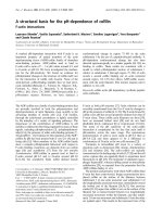
We plot in Figure 2.4 the mean square channel estimation error normalized with
total noise power:
ε
2
0
=
ε
2
4N
0
(2.14)
(a factor of 4 is due to the fact that we add up noise components in all 4 links ) as
a function of the signal-to-noise ratio (SNR)
Γ =
trace{E[Xh(Xh)
∗
]}
4N
0
=
ε
2
s
4N
0
(2.15)
( where ε
2
s
is defined as total received signal power ) of the system. In this study,
we assume all the links have the same power. For the decorrelator approach, we only
present the result for pilot patterns that are invertible. For the MMSE approach,
we present two sets of results, one for those pilot patterns that are invertible, and
another set for those that are not. It is observed that there is a big difference in
performance between the two sets of pilot patterns. If we compare the best results
obtained under the MMSE criterion against those obtained under the decorrelator
approach, we can conclude that there is not much of a difference b etween the two at
large SNR. There is a noticeable difference at low SNR though.
It is also noted that for both approaches with invertible patterns, normalized
estimation error will continuously decrease as SNR increases. In the extreme case
where SNR is infinitely large, estimation error will vanish. Therefore both approaches
are good estimators.
MMSE approach outperforms decorrelator approach in two aspects: (1) certain
patterns of pilot matrix achieve better estimation result, as shown in Figure 2.4. (2)
all patterns are usable, unlike decorrelator approach, where only invertible patterns
can be used.
12
0 5 10 15
−20
−18
−16
−14
−12
−10
−8
−6
−4
−2
received SNR (dB)
estimation error normalized with signal power (dB)
MMSE, X invertible
MMSE, X non−invertible
Decorrelator, X invertible
Figure 2.4: Comparison of the decorrelating and MMSE approaches for channel es-
timation.
On the other hand, decorrelator approach also has two advantages over MMSE
approach: (1) it is easy to implement, and we need only to compute X
−1
, while
MMSE approach requires greater computational complexity. (2) normalized estima-
tion error is linearly changing with SNR, and this fact makes system design more
easily.
Once the receiver obtains channel estimates at the pilot symbol instants, inter-
polation is used to obtain estimates of the fading gains that affect the data symbols.
For brevity, the details are not provided here.
CHAPTER III
MIMO Systems with STBC
3.1 Introduction
One assumption Alamouti made in his study is that channel information, in the
forms of amplitude and phase distortion, is known perfectly to the receiver. In prac-
tice, the issue of channel estimation is non-trivial, especially in a fading environment
where the fading gain can change substantially from one bit to the next. Given im-
perfect channel estimates from pilot symbol assisted modulation (PSAM), one may
wish to find how estimation error can affect bit error performance of STBC. The
author has done a literature survey on how others deal with this problem. The fol-
lowing sections reviews other’s findings, as well as the author’s attempt to make use
of these results to achieve his goal.
3.2 Pairwise Error Probability
[11] describes a simple technique for the numerical calculation, within any desired
degree of accuracy, of the pairwise error probability (PEP) of space-time codes.
This method applies also to the calculation of E[Q(
√
ξ)] for a non-negative random
variable whose moment-generating function φ
ξ
(s) = E[exp(−sξ)] is known.
13
14
Consider the computation of the expectation
P E[Q(
ξ)] (3.1)
where Q(x) = P (ν > x), with real Gaussian random variable with mean zero and
unit variance, and ξ is a nonnegative random variable (independent of ν). A simple
method is advocated to obtain the value of P based on numerical integration. Assume
that the MGF of ξ
φ
ξ
(s) E[exp(−sξ)] (3.2)
is known. In this case, we have
E[Q(
ξ)] = P(∆ < 0) =
1
2πj
c+j∞
c−j∞
φ
∆
(s)
s
ds (3.3)
where ∆ = ξ −ν
2
. It is straightforward to obtain
φ
∆
(s) = E[exp(−s∆)]
= φ
ξ
(s)φ
ν
2
(−s)
= φ
ξ
(s)(1 −2s)
−1/2
(3.4)
Hence,
E[Q(
ξ)] =
1
2πj
c+j∞
c−j∞
φ
ξ
(s)
2s
(1 −2s)
−1/2
ds (3.5)
Here we assume that c is in the region of convergence (ROC) of φ
∆
(s)
Finally we use a Gauss-Chebyshev numerical quadrature rule to obtain a nu-
merical result. Then it can be applied to the calculation of PEP error performance
analysis of a multiple-antenna fading channel in two cases of fading distribution.
1) Independent fading (IF): we assume that the transmitted symbols in a code-
word are affected by independent fading realizations. 2) Block fading (BF): we
assume that the transmitted symbols in a codeword are affected by the same fading
realization. In both cases, the PEP can be expressed as in (3.1) by suitably defining
15
the random variable ξ. We assume t transmit and r receive antennas, and a code
with block length N.
A. Independent Fading Channel
The discrete-time low-pass equivalent channel equation can be written as
y
i
= H
i
x
i
+ z
i
, i = 1 N (3.6)
where H
i
∈ C
r×t
is the ith channel gain matrix, x
i
∈ C
r×t
is the ith transmitted
symbol vector (each entry transmitted from a different antenna), y
i
∈ C
r×t
is the ith
received sample vector each entry received from a different antenna), and z
i
∈ C
r×t
is
the ith received noise sample vector (each entry received from a different antenna).
We assume that the channel gain matrices H
i
are element-wise independent and
independent of each other with [H
i
]
jk
∼ N
c
(0, 1), i.e., each element is circularly
Gaussian distributed with mean zero and variance E[|[H
i
]
jk
|
2
] = 1. Also, the noise
samples are independent with [z]
i
∼ N
c
(0, N
0
).
It is straightforward to obtain the PEP as follows:
P (X →
ˆ
X)
= P(
N
i=1
{||y
i
− H
i
ˆx
i
||
2
− ||y
i
− H
i
x
i
||
2
} < 0)
= P(
N
i=1
{||H
i
(x
i
− ˆx
i
) + z
i
||
2
− ||z
i
||
2
} < 0)
= E
Q
1
2N
0
N
i=1
||H
i
(x
i
− ˆx
i
)||
2
(3.7)
B. Block-Fading Channel
Here we assume that the channel gain matrices H
i
coincide and are equal to H:
16
under this assumption, the channel equation can be written compactly as follows:
Y = HX + Z (3.8)
where H ∈ C
r×t
, X = (x
1
x
N
) ∈ C
t×N
, Y ∈ C
r×N
, and Z ∈ C
r×N
. We assume
independent and identically distributed (i.i.d.) entries
[H]
ij
∼ N
c
(0, 1) E[|[H
i
]
jk
|
2
] = 1
and i.i.d. [Z]
i
j ∼ N
c
(0, N
0
). We obtain, after straightforward calculations
P (X →
ˆ
X) = E
Q
||H∆||
√
2
N
0
(3.9)
where ∆ X −
ˆ
H
C. Evaluation of the Moment-Generating Function
Setting
ξ
1
2N
0
N
i=1
||H
i
(x
i
− ˆx
i
)||
2
IF channel
||H∆||
√
2N
0
BF channel
(3.10)
Then we can evaluate the PEP by resorting to (3.1).
D. In case of imperfect channel estimation
In (3.7) and (3.9), H need to be replaced by
ˆ
H, which is the estimated version
of H.
3.3 Imperfect Channel Estimation in Single Antenna Sys-
tem
Consider a single Tx and single Rx system:
r
=
hs
+
n
(3.11)
17
where h is channel gain, s is transmitted signal (assuming BPSK modulation), n is
AWGN, and r is the received signal.
Given
ˆ
h, channel estimate from PSAM, the receiver makes decision by doing the
following:
z = Re[
ˆ
h
r] (3.12)
If the transmitted bit is +1, then an error is made if the real part of the decision
variable z is negative. Since
ˆ
h and r are correlated, zero mean, Gaussian random
variables, we can use a standard result for the probability of this event[12]
P
b
=
1
2
1 −
Re[ρ]
2
/(1 −Im[ρ]
2
)
(3.13)
where ρ is the correlation coefficient between
ˆ
h and r.
In the case of optimum filter, the correlation coefficient is real, then the error
probability becomes:
P
b
(k) = (1 −ρ )/2 (3.14)
A detailed analysis of PSAM can be found in [13]. Then the author wishes to
extend this result to MIMO systems with STBC.
3.4 Imperfect Channel Estimation in MIMO System with
STBC
According to Appendix C.2 in [12], a method has been used in evaluating bit
error probability in the general case of diversity reception. This method is as follows:
consider a complex Gaussian Random Variable
z =
L
i=1
X
k
Y
k
∗
= z
r
+ jz
i
(3.15)