Developing a 3d multi body simulation tool to study dynamic behaviour of human scoliosis
Bạn đang xem bản rút gọn của tài liệu. Xem và tải ngay bản đầy đủ của tài liệu tại đây (7.54 MB, 167 trang )
DEVELOPING A 3D MULTI-BODY SIMULATION TOOL
TO STUDY DYNAMIC BEHAVIOUR OF HUMAN
SCOLIOSIS
KHATEREH HAJIZADEH
NATIONAL UNIVERSITY OF SINGAPORE
2013
DEVELOPING A 3D MULTI-BODY SIMULATION TOOL
TO STUDY DYNAMIC BEHAVIOUR OF HUMAN
SCOLIOSIS
KHATEREH HAJIZADEH
(B. E, Isfahan University of Technology, Isfahan, Iran)
(M.S., Isfahan University of Technology, Isfahan, Iran)
A THESIS SUBMITTED
FOR THE DEGREE OF DOCTOR OF PHILOSOPHY
DEPARTMENT OF MECHANICAL ENGINEERING
NATIONAL UNIVERSITY OF SINGAPORE
2013
Declaration
I hereby declare that this thesis is my original work and it has been written by me in its
entirety. I have duly acknowledged all the sources of information which have been used
in the thesis.
This thesis has also not been submitted for any degree in any university previously.
Khatereh Hajizadeh
I
List of Publications
Journal Paper
1- Khatereh Hajizadeh, Ian Gibson, Gabriel Liu “Developing a 3D Multi-Body
Model of the Scoliotic Spine with Lateral Bending Motion for Comparison of
Ribcage Flexibility” International Journal of Advanced Design and Manufacturing
Technology, Vol 6, No 1 (2013).
Book Chapter
1- I. Gibson, Khatereh Hajizadeh, K. T. Huynh, B. N. Jagdish, M. J. Huang,
“Development of a Human Spine Simulation System”, in Advances in Therapeutic
Engineering, Taylor & Francis Group (Book Chapter ).
Conference Papers
1- Khatereh Hajizadeh, Gabriel Liu, Ian Gibson, Mengjie Huang “Development of A
Virtual Musculo-skeletal, Multi-body Scoliotic Spine Model”, Proceedings of the 6th
International Conference on Rehabilitation Engineering & Assistive Technology
(2012)
2- Khatereh Hajizadeh, Huang Mengjie, et al, “Developing A 3D Multi-Body Model
of A Scoliotic Spine During Lateral Bending for Comparison of Ribcage Flexibility
and Lumbar Joint Loading to the Normal Model” in ASME 2013 Mechanical
Engineering Congress & Exposition, November 2013, San Diego,
California.(Accepted for publication)
3- Khatereh Hajizadeh, I. Gibson, et al, “Developing A 3D Multi-Body Model of the
Scoliotic Spine to Simulate the Distribution of Loads on The Spine During Normal
Walking”, ASME 2012 Mechanical Engineering Congress & Exposition,
November 2012, Huston, Texas.
4- Khatereh Hajizadeh, I. Gibson, et al, “Developing A 3D Multi-Body Model of The
Scoliotic Spine with Lateral Bending Motion for Comparison of Ribcage
Flexibility” in ICMEAT 2012 International Conference on Mechanical Engineering
and Advance Technology, October 2012, Isfahan, Iran (invited).
5- Mengjie Huang, Taeyong Lee, Ian Gibson, Khatereh Hajizadeh, “Effect of Sitting
Posture on Spine Joint Angles and Forces” Proceedings of the 6th International
Conference on Rehabilitation Engineering & Assistive Technology
II
Acknowledgements
I would like to express my sincere thanks and gratitude to many people who have
directly or indirectly helped me in fulfilling my dream of completing my PhD. First, I would
like to thank my graduate advisors, Dr. Ian Gibson and Dr. Gabriel Liu, and Dr. Lu Wen
Feng for their guidance, encouragement and support throughout the period of my PhD.
Their inspiring guidance, solid encouragement, and helpful insights have paved way for me
to complete this research. I am grateful to the Gait Analysis Lab officer, Ms. Grace, for her
support and assistance in gait analysis experiments. I would also like to express my
gratitude to the graduate office staffs, Ms. Teo Lay Tin, Sharen and Ms. Thong Siew Fah,
for their support.
I am very much indebted to my family, my parents, my sister and my brother who
encouraged and helped me at every stage of my personal and academic life, and longed to
see this achievement come true. I would like to highly thank my friends, Fatemeh
Jamshidian, Ahmadreza Pourghaderi, Saeed Arabnezhad, Sara Adibi, Huyhn Kim Tho,
Wang Xue and especially Huang Mengjie for their tremendous support, both physically
and emotionally.
Last but certainly not least, my gratitude goes to my husband, Ehsan, for his love,
support and encouragement throughout my PhD candidature. No words are sufficient to
express my gratitude and thanks for his support. I am truly appreciative to all that he has
done for me over the years. I could not have reached my goal without his help, support and
love.
Above all, I owe it all to God for granting me the wisdom, health and strength to
undertake this research task and enabling me to its completion.
III
Table of Contents
Declaration.......................................................................................................................... I
List of Publications ........................................................................................................... II
Acknowledgements ......................................................................................................... III
Table of Contents ............................................................................................................ IV
Summary......................................................................................................................... VII
List of tables.................................................................................................................. VIII
List of Figures .................................................................................................................. IX
Chapter 1: Introduction .................................................................................................... 1
1.1 Overview of Clinical Spinal Problems ..................................................................................... 1
1.2 Biomechanical Models of Human Spine ................................................................................ 2
1.3 An introduction about multi-body for spine ........................................................................... 3
1.4 Outline of thesis...................................................................................................................... 5
Chapter 2: Literature review ............................................................................................ 7
2.1 Spine Physiology and Biomechanics...................................................................................... 7
2.1.1 Interbody Joints ............................................................................................................... 9
2.1.2 Ligaments and Joint Capsules ....................................................................................... 12
2.1.3 Muscles of the vertebral columns .................................................................................. 13
2.2 Spine deformity .................................................................................................................... 14
2.2.1 Kyphosis ........................................................................................................................ 15
2.2.2 Scoliosis......................................................................................................................... 15
2.2.3 Kyphoscoliosis .............................................................................................................. 16
2.3 A review of methods for quantitative evaluation of scoliotic spine curvature ..................... 16
2.4 Biomechanics, modeling and simulation of the scoliotic spine............................................ 19
2.5 Spine model with using motion capture system .................................................................. 24
2.6 Spine models with scoliosis condition .................................................................................. 26
2.6.1 Finite element (FE) scoliosis models ............................................................................. 28
2.6.2 Scoliosis gait analysis ..................................................................................................... 29
2.7 Summary............................................................................................................................... 31
IV
Chapter 3: Scoliotic spine model development in LifeMOD and integration with
Motion Capture ................................................................................................................ 33
3.1 Introduction .......................................................................................................................... 33
3.2 General human modeling paradigm..................................................................................... 35
3.3 Modeling methods ............................................................................................................... 37
3.3.1 Passive Joint................................................................................................................... 38
3.3.2 Recorded Joint Models .................................................................................................. 38
3.3.3 Trained muscle .............................................................................................................. 38
3.4 Fully Discretized Musculo-Skeletal Multi-Body model ......................................................... 39
3.5 Muscle formulation .............................................................................................................. 44
3.6 Scoliosis condition ................................................................................................................ 45
3.6.1 Method 1: Reconstruction of the spine based on X-ray images of the scoliosis subject
................................................................................................................................................ 46
3.6.2 Method 2: Using motion capture (Mocap) data ........................................................... 47
3.7 Motion capture system (motion capture model) ................................................................. 47
3.7.1 Motion capture system ................................................................................................. 48
3.7.2 Motion Capture analysis ................................................................................................ 51
3.8 Conducting Musculo-skeletal Human-Body with Mocap data ............................................. 55
3.9 Validation of the Spine Model .............................................................................................. 57
3.9.1 Compare the results with simulation models and experimental data .......................... 57
3.9.2 Comparison of the results with experimental data (in-vivo experiment) ..................... 58
3.10 Loading on the spine .......................................................................................................... 59
3.11 Lifting activity during lateral bending exercise................................................................... 60
3.12 Summary............................................................................................................................. 62
Chapter 4: Modeling hypothesis scoliosis spine and test the stability under static
loads................................................................................................................................... 63
4.1 Introduction .......................................................................................................................... 63
4.2 Curve patterns of scoliotic spine .......................................................................................... 63
4.3 Creating the spine curvature based on 2D X-ray images from scoliosis patients ................ 65
PT1: Spine with thoracolumbar curve .................................................................................... 67
PT2: Spine with thoracic curve ............................................................................................... 68
PT3: Spine with double curve ................................................................................................. 69
4.4 Spine Stability analysis for three scoliosis models ............................................................... 69
V
4.5 Investigating the Lateral and Anterior/Posterior (A/P) motion of normal and scoliosis
models using forward dynamics ................................................................................................. 71
4.5.1 Evaluation of the stability of the models ...................................................................... 72
4.5.2 Body segment motion of the scoliotic patient under external 1260 N A/P and 600 N
lateral shear forces applied on T7 .......................................................................................... 73
4.5.3 Apply horizontal (A/P) force on T7 and study its effect on the lumbar joint force and
torque ..................................................................................................................................... 76
4.5.4 Apply horizontal (lateral) force on T7 and study its effect on the lumbar joint force and
torque ..................................................................................................................................... 79
4.5.5 Nature of the mechanical loads on the spine ............................................................... 80
4.6.
Summary......................................................................................................................... 82
Chapter 5: Dynamic behaviour of the human body with scoliosis spine .................... 83
5.1 Introduction .......................................................................................................................... 83
5.2 Musculo-skeletal human-body modeling in dynamic exercises, lateral bending, flexion and
axial rotation .............................................................................................................................. 86
5.2.1 Description of the human subjects studied in this work ............................................... 87
5.2.2 Experimental procedure ................................................................................................ 88
5.3 Results and discussion .......................................................................................................... 91
5.3.1 Lateral bending .............................................................................................................. 91
5.3.2 Bending forward/backward......................................................................................... 102
5.3.3 Axial Rotation .............................................................................................................. 106
5.3.4 Discussion .................................................................................................................... 108
5.4. Investigating the effect of corrective spine surgery on dynamic behaviour of the spine
after surgery ............................................................................................................................. 111
5.5. Summary............................................................................................................................ 114
Chapter 6: Conclusion ................................................................................................... 116
6.1 Discussion of the model ..................................................................................................... 117
6.1.1 Construction of the model and basic validation ......................................................... 117
6.1.2 Incorporating the scoliosis condition into the model................................................... 117
6.1.3 Dynamic behaviour of the real normal and scoliosis subjects in basic motion tasks . 118
6.2 Model limitations and recommendations for the future research .................................... 119
6.3 Global validation ................................................................................................................. 120
VI
Summary
Knowledge of the movements of whole spine is important for evaluating clinical pathologic
conditions that may potentially produce unstable situations in human body movements. At
present these are few studies that report systematic three-dimensional (3D) movement
analysis of the whole spine. Scoliosis is one of the asymmetric conditions in the spine.
Scoliosis is a complicated condition characterized by a lateral curvature of the spine and
accompanied by rotation of the vertebrae about its axis.
The objective of this study is to simulate a 3D multi-body model of the human body,
especially body with spine deformity (scoliosis) for investigating various medical
applications. This personalized multi-body scoliotic spine model is developed based on
patient anthropometric data. Such a model is able to capture the dynamic interactions
between vertebrae, muscles, ligaments, and external boundary conditions. In this study, the
scoliotic spine of three patients was modeled using 2D X-ray images to investigate the
biomechanics of abnormal spines which were examined in upright posture. The spine joint
forces and torques were found in this posture for all models and the results were discussed.
Furthermore, the biomechanics of human scoliotic and normal spine in daily maneuvers
such as flexion, bending and twisting exercises were investigated with conducting
musculoskeletal model with motion capture data of the subjects. The range of motion
(ROM) of the patient was compared with the ROM of the healthy subject with similar
anthropometric data in all exercises. The force and torque in lumbar joints from scoliosis
simulated model in these exercises were compared to those of the normal one. Finally, this
simulation model was used to study the effect of corrective spine surgery (instrumentation)
on the spinal forces and range of motion. This model can be used as a tool for wheelchair
design or other seating systems design which may require attention to ergonomics as well
as assessing biomechanical behaviour between normal and scoliotic spines.
VII
List of Tables
Table 3.1 T-Series camera performance …………………………………...................
50
Table 4.1 Data on patients and scoliosis curve patterns ……………………...............
67
Table 4.2 External torque on the lumbar region ………………………………..……
82
Table 5.1 The anthropometric data of two subjects used in the
experiments………………………………………………………………...................
89
Table 5.2 Abdomen, back and neck muscle groups …………………………………....
95
Table 5.3 Average joint force values in the lumbar joints in the female normal
model....
98
Table 5.4 Joint force on the lumbar region in normal subject………………...………...
105
Table 5.5 Magnitude joint force in lumbar joints in the normal model…….………...
108
VIII
List of Figures
Figure 2.1 Cervical, thoracic, lumbar and sacral region of the spine ………………….......
8
Figure 2.2 side view of the spine showing the natural curvatures of the spine …................
9
Figure 2.3 The structure of a typical vertebra showing the anterior and posterior sections
of the spin……………………………………………….....................................................
9
Figure 2.4 Interbody joint and facet joint ………………………….…………...................
10
Figure 2.5 Intervertebral disc ………………………....………………………………….
11
Figure 2.6 Translations and rotations of one vertebra in relation to an adjacent vertebra
(a) Side-to-side translation (b) Superior and inferior translation (c) Anteroposterior
translation (d) Side- to- side rotation (e). Transverse rotation (d). Anteroposterior rotation
12
(Pamela K. Levangie 2005)(Pamela K. Levangie 2005)(Pamela K. Levangie
2005)(Pamela K. Levangie 2005)(Pamela K. Levangie 2005)(Pamela K. Levangie
2005)(Pamela K. Levangie 2005)(Pamela K. Levangie 2005)(Pamela K. Levangie
2005)(Pamela K. Levangie 2005)
Figure 2.7 Six types of spine ligaments ……..................................................……………..
13
Figure 2.8 Biomechanical planes …………………….....………………………………...
14
Figure 2.9 lateral view of (1) normal spine and (2) spine with kyphosis ……….................
15
Figure 2.10 back view of the spine with Scoliosis deformity ……......……….…………
16
Figure 2.11 Evaluation of coronal spinal curvature in 2D images (Vrtovec, Pernuš et al.
2009), (a) Ferguson method (Ferguson 1930), (b) Cobb method (Cobb 1948), (c)
Greenspan index …………………………………....………………………………….
19
Figure 3.1 LifeMOD applications …………………………………....……………………
35
Figure 3.2 Back view of (a) the default model and (b) complete discretized spine model...
37
Figure3.3 Simulation flowchart …………………………………………………...............
37
Figure 3.4 A functional spinal unit ……………………………....………………………..
40
Figure 3.5 Front and back view of the abdomen and lumbar muscles ……………………
42
Figure 3.6 Side and back view of ligaments in the cervical region ………………………
43
Figure 3.7 Intra abdominal pressure joint in front and side view ………………….............
44
Figure 3.8 Flowchart of modeling a detailed human model …………………...................
44
Figure 3.9 the scoliotic spine model which created based on the X-ray images …………
47
Figure 3.10 “L” shape 2D structure ………………………….....………………...............
50
Figure 3.11 5 marker L-frame used to calibrate the cameras and set the Vicon origin ……
51
Figure 3.12 The model which is in Vicon Nexus from motion data (a) plug in model (b)
spine in plug in model (c) spine in scoliosis-specific model ................................................
53
Figure 3.13 Standard plug-in-Gait marker placement protocol ............................................
53
IX
Figure 3.14 A subject with marker sets (a) Front and (b) back view of a subject with plug
in marker set (c) back view of a subject with scoliosis- specific marker set …....................
54
Figure 3.15 Motion agent configuration ...............................................................................
57
Figure 3.16 Spine model under external force applied on T7 ..............................................
59
Figure 3.17 Schematic illustration of the loads applied on the disc (a) compression load
(b) shear forces……………………………………………………………………………..
61
Figure 3.18 Schematic illustration of the torques applied on the disc (a) abduction/
adduction (b) medial/lateral rotation, or (c) flexion/extension …………………………….
61
Figure 3.19 Reaction force on the three lower lumbar vertebrae in lateral bending
exercise with different weight lifting .................................................................................... 62
Figure 3.20 Reaction force on the two upper lumbar vertebrae joints and thoracolumbar
joint in lateral bending exercise with different weight lifting ..............................................
63
Figure 3.21 Reaction force on the lumbar vertebrae joints and thoracolumbar joint in
lateral bending exercise with different weight lifting (average of value in left and right
bending) ……………………………………………………………………………………
63
Figure 4.1 Cobb angle of a scoliotic spine in frontal plane ..................................................
65
Figure 4.2 Curve patterns of scoliotic spine .........................................................................
66
Figure 4.3 location of the COM of the vertebrae in X-ray image ........................................
68
Figure 4.4 Front and back view of X-ray images and 3D model of PT1 in erect posture ...
69
Figure 4.5 PT2’s spine curvature in x-ray image and simulation model in front and back
view .....................................................................................................................................
69
Figure 4.6 PT3’s spine curvature in X-ray image and simulation model in front and back
view ......................................................................................................................................
70
Figure 4.7 Head velocity (cm/s) of three models during stability simulation ......................
72
Figure4.8 Anterior and posterior view of the complete discretized scoliosis spine model ..
73
Figure 4.9 Posterior view (a)Normal model (b)Scoliosis model with 38° Cobb angle (c)
Scoliosis model with 52° Cobb angle (d) Scoliosis model with 62° Cobb angle.................
73
Figure 4.10 Stability test of normal and scoliosis simulated models ...................................
76
Figure4.11 The variation of lateral head displacement of scoliosis models with respect to
the normal model in first simulation ....................................................................................
76
Figure 4.12 Head displacement of all simulated models in frontal plane after applying
600N lateral shear force on T7 ............................................................................................
76
Figure 4.13 Lateral shear force in four simulated models ...................................................
78
Figure 4.14 Lateral shear force pattern of the lumbar vertebral joints ................................
78
Figure 4.15 Joint torques in the lumbar region (a) Lateral torque (b) Twisting torque …..
79
Figure 4.16 Joint torques within four simulated models (a) Lateral (b) Twisting ................ 79
X
Figure 4.17 the lumbar joint forces in four simulated model ...............................................
80
Figure 4.18 Force and torque diagram on the lumbar spine .................................................
82
Figure 4.19 Free body of the lumbar spine diagram under external lateral force................
82
Figure 5.1 Basic spine bending tasks (a) Flexion in sagittal plane. (b) Lateral flexion in
coronal plane. (c) Axial rotation in transverse plane (Pamela K. Levangie 2005) ............... 85
Figure 5.2 Lateral flexion task (Pamela K. Levangie 2005) ...............................................
86
Figure 5.3 Spine in flexion (a)flexion posture (b)vertebra in flexion (c)vertebra in
extension (Pamela K. Levangie 2005) ..................................................................................
86
Figure 5.4 Spine in axial rotation (a) Axial rotation Posture (b) Vertebrae rotates toward
the right (Pamela K. Levangie 2005) .................................................................................... 87
Figure 5.5 Different postures (a) Right lateral bending (b) Left lateral bending (c) Right
axial rotation (d) Left axial rotation (e) Bending forward (f) Bending backward (g)
Upright sitting posture .........................................................................................................
89
Figure 5.6 Musculoskeletal body model trained by motion capture data in inverse
dynamic analysis ................................................................................................................... 90
Figure 5.7 Thorax angle in frontal plane (a) data from the motion capturing data, (b) data
from computational analysis ................................................................................................
92
Figure 5.8 back view of the neck, back and abdomen muscle groups .................................
93
Figure 5.9 Average joint forces: in the normal female model at (a) L4/L5 joint and (b)
lumbosacral joint; in the scoliosis female model at (c) L4/L5 joint and (b) lumbosacral
joint .......................................................................................................................................
95
Figure5.10 X-ray images of the scoliosis female subject in bending right and left postures
96
Figure 5.11 The variation of lumbar joint forces in (a) left bending (b) upright standing
and (c) right bending in scoliosis respect to the normal female models ............................... 98
Figure 5.12 The variation of lumbar joint forces in (a) left bending (b) upright standing
and (c) right bending in scoliosis respect to the normal male mode.....................................
99
Figure 5.13 X-ray images of the scoliosis male subject in upright standing, bending right
and left postures ....................................................................................................................
100
Figure 5.14 Comparison between joint forces in normal and scoliosis female models at
L4/L5 and lumbosacral joints (a) Compression load (b) magnitude force (c) lateral shear
force and (d) anterior posterior shear force..........................................................................
101
Figure 5.15 Comparison between joint forces in normal and scoliosis male models at
L4/L5 and lumbosacral joints ...............................................................................................
102
Figure 5.16 normalized lumbar joint force in normal and scoliosis models (N, PT, f and
m represent normal, scoliosis, female and male subjects respectively) ...............................
102
XI
Figure 5.17 Angle in flexion and extension postures (a) positive in flexion (b) negative in
extension ..............................................................................................................................
103
Figure 5.18 (a) subject (b) simulation model in Nexus (c) Simulation model in LifeMOD
in maximum extension posture (d) subject (e) simulation model in Nexus (f) Simulation
model in LifeMOD in maximum flexion posture .................................................................
103
Figure 5.19 The variation of lumbar joint forces in (a) flexion (b) upright standing and (c)
extension in scoliosis respect to the normal model (in female and male subjects) ..............
105
Figure 5.20 Normalized lumbar joint force to the subject’s weight in maximum flexion
and extension of normal and scoliosis models .....................................................................
106
Figure 5.21 (a) simulation model in Nexus (b) Simulation model in LifeMOD in
maximum left rotation posture, maximum right rotation posture and upright standing
posture. .................................................................................................................................
107
Figure 5.22 The variation of lumbar joint forces in (a) Left rotation (b) upright standing
and (c) Right rotation in scoliosis respect to the normal model ...........................................
108
Figure 5.23 Loads normalized by standing in normal and scoliosis female models at
L5/S1 joint ............................................................................................................................
110
Figure 5.24 Loads normalized by standing in normal and scoliosis female models at
L4/L5 joint ............................................................................................................................
110
Figure 5.25 Loads normalized by standing in normal and scoliosis female models at 5
lumbar joints joint .................................................................................................................
110
Figure 5.26 X-ray image of PT2 with scoliosis spine before and after instrumentation
surgery. The convexity of the spine was to left side. ...........................................................
111
Figure 5.27 joint forces in lumbar region of the patient doing the left/right lateral bending
before and after surgery. .......................................................................................................
112
Figure 5.28 joint forces in lumbar region of the patient doing the flexion/extension
bending before and after surgery. ........................................................................................
113
Figure 6.1 Discretized ribs and sternum of the real case ......................................................
120
XII
Chapter 1: Introduction
Chapter 1: Introduction
1.1 Overview of Clinical Spinal Problems
Investigation into the biomechanics of human spine in different postures is becoming
increasingly important. The human spine is an essential bodily component which
undertakes complex motions and provides stability and protection for the spinal cord during
a variety of loading conditions. However, it is also a very vulnerable part of our skeleton
that is subject to many medical problems such as whiplash injury, low back pain and
scoliosis. People with sedentary jobs may spend hours sitting in a chair in a relatively fixed
position, with their lower back forced away from its natural lordotic curvature. Sustained
lumbar flexion (Adams and Dolan 1995) and static loading (Callaghan and McGill 2001)
suggest possible risks linking prolonged sitting with lower back disorders. Extensive
studies have been conducted to investigate the biomechanics of the human spine in different
sitting postures.
In clinical spinal problems, “scoliosis” is a less common but more complicated disease in
comparison with low back pain or whiplash injury. Scoliosis is generally defined as a threedimensional deformity of the spine and trunk affecting 1.5% to 3% of the population most
commonly occurring in young women (Weinstein, Dolan et al. 2008). Scoliosis is basically
a source of instability in the vertebral column. This instability may cause other diseases
which are not well understood yet. Current scoliosis treatments are mostly mechanical, i.e.
based on external load application that can potentially be long and uncomfortable for the
patients. Severe cases of scoliosis are generally treated by spinal instrumentation and fusion
to stabilize and straighten the curve in 3D space (Chen, Chen et al. 2005, Desroches, Aubin
et al. 2007). Decisions on instrumentation parameters such as position of instrument, the
number of implants, type and shape of the rod, etc. mainly depends on the surgeons’
experience. The experience and preferences of the surgeon, the objectives of surgical
correction as well as the lack of standardized strategies of instrumentation can be the main
reasons for variability in the operation strategy and outcome.
Therefore, collaboration between mechanical, computer engineers and orthopedic surgeons
is inevitable in this field. Because of the limitations of the treatment methods,
biomechanical modeling and simulations has found great importance to give future spine
surgeons training before the real surgical operation. The computer models have been
capable of simulating various scoliosis treatments including bracing (Perie 2004) and
1
Chapter 1: Introduction
instrumentation (Aubin 2003, Lafage 2004, Desroches, Aubin et al. 2007). To help
surgeons gain insight into complex biomechanics of scoliotic spines and to propose better
surgical plans before spine correction operations, development of a virtual bio-fidelity
musculo-skeletal multi-body scoliotic spine model would be very helpful.
1.2 Biomechanical Models of Human Spine
Knowledge of the movements of the whole spine and lumbosacral joint is important for
evaluating clinical pathologic conditions that may potentially produce unstable situations
in human body movements. In addition, evaluation of internal actions such as contraction
force of muscles, force and stress interactions in body joints (e.g. articular joints) plays an
important role in understanding, treatment and physical rehabilitation of biomechanically
related diseases. Despite the great importance of understanding these parameters, there are
limited feasible experimental techniques for quantitative (or even qualitative) evaluation of
internal interaction between bonds, cartilages, joints and soft tissues (muscles, tendons,
etc.) directly and in a painless fashion. This important requirement, as well as lack of a
proper understanding of the biomechanics of the human body was the main reason for
emerging computational biomechanics and developing biomechanical models to evaluate
the behaviour of the different parts of the body.
Computer modeling simulation has been also applied to try and help to solve some spine
problems (Fagan, Julian et al. 2002). Multi-body and finite element models, or a
combination of the two, are popular simulation tools that can contribute significantly to our
understanding of the biomechanics of the spine. Although a great deal of computational
power may be required, finite element models (FEMs) are helpful in understanding the
underlying mechanisms of injury and dysfunction, leading to improved prevention,
diagnosis and treatment of clinical spinal problems. These models often provide estimates
of parameters that in vivo or in vitro experimental studies cannot obtain easily. Although
they can predict internal stresses, strains and other biomechanical properties under complex
loading conditions, they generally only consist of one or two motion segments. At present
there are few studies that report systematic three-dimensional (3D) motion analysis of the
whole spine.
Compared to FEMs, multi-body models have advantages such as less complexity, less
demand on computational power, and relatively simpler validation requirements. Multi-
2
Chapter 1: Introduction
body models possess the potential to simulate the kinematics and kinetics of the whole
human body.
1.3 An introduction about multi-body for spine
In one early model, Chaffin represented a very simple spine in which back extensors were
represented by a single muscle equivalent (Chaffin 1969). One of the first attempts to
construct a more realistic model incorporated the geometry of individual muscle fascicles
derived from McGill’s own cadaver dissections (McGill and Norman 1986). This work
describes a dynamic model of the low back that incorporates extensive anatomical detail of
a three-dimensional musculo-ligamentous-skeletal system. The study suffered however
from not explicitly reporting the anatomical information used. Since then, the anatomy of
the lumbar erector spine and the lumbar multifidus has been described in great detail
(Bogduk 1980, Macintosh and Bogduk 1986, Macintosh and Bogduk 1987) and this
information has become a common basis for detailed biomechanical models (Bogduk,
Macintosh et al. 1992a, Macintosh, Bogduk et al. 1993, Stokes and Gardner-Morse 1995,
Van-Dieen 1997). These models excluded quadratus lumborum muscles and later, Zee et
al. (Zee, Hansen et al. 2007) presented a more detailed spine model incorporating most of
the necessary lumbar muscles. In most of the previous models, only a portion of the spine
(for example the lumbar spine) was modeled, whereas the other regions (e.g. thoracic spine
and cervical spine) were left as rigid segments.
Based on the studies presented above, it is found that modeling of a detailed whole human
spine has not been completely investigated. Although there were finite element spine
models created for the whole spine, the influence of spinal muscles as well as ligaments
was not fully taken into account in these models. Furthermore, in multi-body methods,
many authors have attempted to develop human spine models. Nevertheless, these models
are still incomplete.
This project mainly focuses on developing a 3D multi-body simulation tool to study
dynamic behaviour of human musculoskeletal system. In this work, a detailed realistic 3D
model of the whole spine is designed which enables us to consider the effects of structural
abnormalities of scoliosis as well. This model is constructed based on measurements of the
anatomical (biomechanical) parameters of healthy and scoliosis real subjects and is
developed in the LifeMOD Biomechanics Modeler (LifeMOD). LifeMOD is a dynamic
modeling tool (software). It is a plug-in module to ADAMS (Adams) and is able to
3
Chapter 1: Introduction
construct multi-body model of the human musculoskeletal system with different boundary
conditions and/or environments. The kinetics and kinematics of the developed model in
this system can be analyzed by a combination of inverse and forward dynamics (Roberson
and Schwertassek 1988).
Recently, LifeMOD Biomechanics Modeler (LifeMOD) has been popularly used as a
multi-body dynamic simulation platform in numerous modeling researches. A dynamic
simulation of the cervical spine containing a disc implant was performed using LifeMOD
to understand the intradiscal forces/pressures, bending moments and vertebral body
rotation (De-Jongh, Basson et al. 2007). In a similar manner, a human-wheelchair
musculoskeletal model was generated with LifeMOD to analyze the cervical spine of a
wheelchair user subjected to frontal and side impacts (Kim, Yang et al. 2007).
The main goal of this research work is to investigate and develop a simulation tool to study
biomechanics, more specifically kinematics, of the human body with scoliosis spine
models. This model is able to provide valuable information such as internal forces between
vertebrae, joints, relation between the angles of the joints and muscle tensions and joint
torques. It also has the potential to calculate the forces resulted from interaction between
rods, screws, and implants used for instrumentation correction of the spine deformity. The
outcomes of this simulation and analysis tool can be useful for orthopedists or surgeons to
acquire valuable information about the biomechanics of the body which may enable them
to plan the operation/treatment more accurately, to optimize the design procedure of the
biomechanical correction devices (braces, implants, etc.), or to predict the results of the
treatment.
The necessary factor to build such a simulation tool is in developing a realistic model of
the human body in which all biomechanical and geometric details of the spine and its
deformities has been taken into account. In the current work LifeMOD was used as a
platform to create a “multibody” biomechanical model of the spine in which the scoliosis
deformity of the spine can be considered. Real-time motion capture analysis of the real
subject (base on whom the model has been constructed) have been used for validation of
the results of this multibody model.
The personalized multi-body scoliotic spine models represented in this study are based on
patient anthropometric data. These models are able to capture the dynamic interactions
between vertebrae, muscles, ligaments and external boundary conditions (e.g. representing
the probable instrumentation of external forces).
4
Chapter 1: Introduction
It is noteworthy that this research was done in close relationship with National University
Health Center (spine center) and we took the benefit of medical advices from Dr. Gabriel
Liu who is a surgeon specialist in scoliosis spine treatments. This model can furthermore
be used as a tool for wheelchair or other seating systems design which may require attention
to ergonomics as well as assessing biomechanical behaviour between normal and scoliotic
spines. The force in lumbar joints from scoliosis simulated model in daily maneuvers such
as flexion/ extension, bending and twisting were compared to those of the normal one.
1.4 Outline of thesis
In this study, a multi-body spine model presents to quantify the various biomechanical
aspects which are important in scoliosis assessment. As mentioned earlier, this model is
capable of providing fundamental biomechanical information about the scoliotic spine
which can be required for optimization of the spine deformity treatments methods.
Chapter 2 gives an overview of biomechanics of spine and spine deformity, Biomechanical
models of spine deformity and a review of methods for quantitative evaluation of scoliotic
spine curvature.
The concepts of the spine biomechanics and modeling methods have been explained in
chapter 3. It presents the investigation on simulation tools which are used in this study
followed by the development of the detailed scoliosis modeling method in various stages.
The procedure of constructing of the final multibody model has been described in chapters
3 and 4. In these chapters, initially the general structure of the model in the light of different
anatomical structures has been described and the assumption and simplifications
considered in the simulation process have been explained. Chapter 3 is concluded by
validation of the model and discussion about the role of soft tissues (ligaments and back
and lumbar muscles) and intra-abdominal pressure on the stability of the model.
Being a generic model, the geometrical aspects of the model (e.g. the severity of the
scoliosis deformity) can be easily changed in this model. In chapter 4, two methods for
modeling of the scoliosis spine were presented. The loading condition in sagittal and frontal
planes on hypothetic scoliosis spine with different Cobb angle was investigated in this
chapter as well.
Simulation results of the detailed (refined) spine model of normal and scoliosis conditions
tested in different body motions and configurations has been reported in chapter 5. In this
chapter the related simulation challenges and limitations has been also discussed.
5
Chapter 1: Introduction
Furthermore, the performance of the model with scoliosis condition is tested as the final
goal of the musculoskeletal model with conducting it with Mocap data. Dynamic behavior
of the scoliosis subject during daily activities like bending and twisting was investigated
and the mechanical behavior of the scoliosis spine was compared to those of the healthy
spine in this chapter. According to the results subjects with scoliosis condition endure
higher force during bending and twisting movements compared to normal ones.
In chapter 6, the presented results and methods in the previous chapters as well as the
strength and limitations of the developed models will be discussed. Summarizing the
findings of the work, recommendations for improvement of the current method in the future
works has been presented. Further information about the modeling and simulation details
steps has been extensively presented in Appendices. The appendices give other relevant
information including a step by step guide to the modeling technique.
6
Chapter 2: Literature review
Chapter 2: Literature review
2.1 Spine Physiology and Biomechanics
Understanding the physiology and biomechanics of the spine is necessary to get insight into
the motion and load carrying capacity limitations of the spine. The main function of the
spine together with the trunk muscles surrounding the spine is to support the weight of the
head and upper extremity limbs and their consequent forces and moments to maintain the
upright body posture. In addition, spine is responsible to control the relative motion of the
head, neck, trunk and the pelvic region. It also provides a base for ribs and connects the
upper and lower body via the sacrum which connects the spine to the pelvis. Last but not
the least, the spine has the very important role of protecting the spinal cord against any
physical damage due to shocks or excessive movements (Panjabi 1990).
The human spine is made up of 24 vertebrae which are stacked on top of one another to
create the spinal column. The bones of the spine, the vertebrae, are the hard elements of the
structure which are separated from each other by soft inter-vertebrae disks. While vertebrae
support the loads as levers, the intervertebral disks act as confined joints between the
vertebrae. The unique combination of vertebrae and the disks provides numerous degrees
of freedom to the human body such as forward-backward and lateral bending, turning and
rotating (twisting) around the body’s central axis. The spine is tied together by ligaments
and actuated by muscles (Edidin, Kurtz et al. 2006). The muscles attached to the spine act
as actuators which provide the required forces (moments) and stiffness required for
different modes of body mobility (e.g. standing, bending, twisting, etc.) and more
importantly stability of the body.
Applying external loads or relative movements to the spinal system, imposes internal
tensions and stresses to the components of this system (i.e. vertebrae, disks, ligaments, and
muscles). If these loads are greater than the maximum magnitude that a disk, vertebra or
ligament can support, the whole system or a part of that will fail.
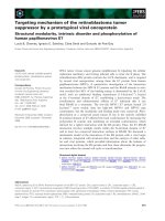
The spine is divided into cervical, thoracic, lumbar, and sacral regions. Figure 2.1 shows
the different regions of the human spine. The seven cervical vertebrae of the neck provide
maximum flexibility and range of motion for the head. These vertebrae are nominated C1
through C7. The 12 thoracic vertebrae (T1 through T12) support the ribs and the organs
that hang from them. The five vertebrae under the thoracic region constitute the lumbar
7
Chapter 2: Literature review
region. These five lumbar vertebrae (L1 through L5) are subjected to the highest forces and
moments. The lumbar section of the spine has the critical responsibility of supporting the
total weight of the trunk and upper extremity limbs of the body and also provides the
maximum capability of bending and twisting as compared to the other parts of the spine.
Hence, they are the largest and strongest vertebrae of the spine. These bones (vertebrae)
are optimized for structural support rather than flexibility. At the lower extremity of the
spine, Five bones that are joined together in adults form the sacrum and three to five bones
fused together to form the coccyx or tailbone.
Figure 2.1 Cervical, thoracic, lumbar and sacral region of the spine (Edidin, Kurtz et al. 2006)
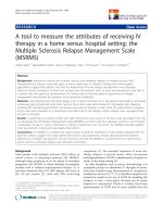
From the back view, the vertebrae form a straight column keeping the head centered over
the body. From the side view however, the spine is consisting of different curves as can be
seen in Figure 2.2. These natural curves position the head over the pelvis and work as shock
absorbers to distribute mechanical stress during movement (Edidin, Kurtz et al. 2006).
8
Chapter 2: Literature review
Figure 2.2 Side view of the spine showing the natural curvatures of the spine
All vertebrae have almost a similar geometry. The main section of each vertebra (anterior
section) is a round block of bone, called the vertebral body that is optimized for sustaining
compressive loads. The size of the vertebra gradually increases from the neck to the lower
parts of the spine. This increased size helps to maintain the balance of the spine and also
supports the larger muscles that are connected to the lower parts of the spine. The posterior
elements of the spine are optimized to provide the maximum protection of the spinal cord
and also proper connection points for attachment of the muscles (Kurtz and Edidin 2006).
The structure of a typical vertebra is shown in Figure 2.3.
Figure 2.3 The structure of a typical vertebra showing the anterior and posterior sections of the
spine (figure from )
2.1.1 Interbody Joints
As mentioned earlier, because of its flexibility, the spine allows relative motion of limbs
connected to that with respect to each other or with respect to the rest of the body. The
9
Chapter 2: Literature review
flexibility of the spine itself sources from the relative motion of the vertebrae with respect
to each other which is controlled through interbody and facet joints (Figure 2.4).
Figure 2.4 Interbody joint and facet joint (Pamela K. Levangie 2005)
The facet joints are composed of the articulations between the right and left superior
articulating facets of a vertebra and the right and left inferior facets of the adjacent cranial
vertebra. The facet joints are diarthrodial joints and have regional variations in structure
(Wooley, Grimm et al. 2005).
Interbody joints are composed of two successive vertebral bodies, the gaps between which
are filled with intervertebral disks. The intervertebral discs form a viscoelastic cushion
which separates the vertebrae from each other and provides a higher range of motion
(Figure 2.5). The other important function of the intervertebral disk is to transfer the load
from upper vertebra to the lower one in a smooth and attenuating manner. The intervertebral
disks constitute about 20-30% of the total height of the spinal cord. The size and thickness
of the disk is not uniform and changes based on the amount of load which should be
supported by the disk and also the motion range of the specific spine region. Therefore by
increasing the load, the thickness of the disk gradually increases from ~ 3 mm in the
cervical region with minimum weight load to about 9 mm in the lumbar region with
maximum weight-load capacity (Panjabi 1990). The relation between the motion range and
the thickness of the disk is not straight forward. An important factor which determines the
maximum range of motion is the disk thickness to vertebra height ratio (Kapandji and
Honore 1981), the greater the ratio, the greater the mobility. This ratio is the greatest in the
cervical region followed by the lumbar region and is the minimum in the thoracic part of
the spine.(Pamela K. Levangie 2005)
10
Chapter 2: Literature review
Figure 2.5 Intervertebral disc ( />
Function of interbody joints provide different kinds of motions such as gliding, distraction,
and tilt motion. Gliding motion is a relative linear movement of the vertebrae in sagittal
and frontal (lateral) planes. Tilt motion is rotation of the vertebra in sagittal, frontal, and
transverse planes. Distraction (compression) is linear displacement of the vertebrae in the
axial direction. Combination of these motions provides six degree of freedom as can be
seen in Figure 2.6. The magnitude of these motions is generally a function of structure of
the disk and vertebral body and also the support of the ligaments (Panjabi 1990). In the
current study, interbody and facet joints are referred to as “intervertebral” joints.
11