Application of computational intelligence for faulty detection and diagnosis of induction motors and electromechanical systems
Bạn đang xem bản rút gọn của tài liệu. Xem và tải ngay bản đầy đủ của tài liệu tại đây (997.32 KB, 99 trang )
APPLICATION OF COMPUTATIONAL INTELLIGENCE
FOR FAULT DETECTION AND DIAGNOSIS OF
INDUCTION MOTORS AND ELECTROMECHANICAL
SYSTEMS
ZHANG YIFAN
NATIONAL UNIVERSITY OF SINGAPORE
2012
APPLICATION OF COMPUTATIONAL INTELLIGENCE
FOR FAULT DETECTION AND DIAGNOSIS OF
INDUCTION MOTORS AND ELECTROMECHANICAL
SYSTEMS
ZHANG YIFAN
B. Eng. (Hons.), Tianjin University
A THESIS SUBMITTED
FOR THE DEGREE OF MASTER OF
ENGINEERING
DEPARTMENT OF ELECTRICAL AND COMPUTER
ENGINEERING
NATIONAL UNIVERSITY OF SINGAPORE
2012
DECLARATION
I hereby declare that the thesis is my original work and it
has been written by me in its entirety.
I have duly acknowledged all the sources of information
which have been used in the thesis.
This thesis has also not been submitted for any degree in
any university previously.
ZHANG YIFAN
September 2012
ACKNOWLEDGEMENTS
First of all, I would like to express my deep and hearty gratitude to my supervisor,
A/Prof Chang Che Sau, whose invaluable encouragement, support and guidance
throughout my Engineer Master studies ensured me to develop a better understanding of
the project, overcome all the difficulties in the research, and finally finish this thesis.
Without his insightful advices and constant help, this thesis would not have been possible.
I would like to acknowledge research fellow, Dr. Wang Zhaoxia, for her kind support
and knowledge transfer of FFT and ICA.
I am also thankful to research engineer, Miss Lu Wenjing, for her many generous help
and constructive discussions in my research.
I want to take this chance to thank the technologist-in-charge of the Power Systems
Laboratory, Mr. Seow Hung Cheng, for organizing seminar with our external co-worker,
maintaining of laboratory equipment and providing assistance.
I wish to thank research engineer, Miss Wu Di, for her immense knowledge,
motivation and enthusiasm, which help me in my study and life in Singapore.
Finally, I would like to sincerely thank my friends and family for their endless,
unconditional, and dedicated love and constant support.
TABLE OF CONTENTS
SUMMARY ......................................................................................................................... i
LIST OF TABLES ............................................................................................................. iii
LIST OF FIGURES ........................................................................................................... iv
LIST OF SYMBOLS AND ABBREVIATIONS .............................................................. vi
CHAPTER 1
INTRODUCTION ................................................................................... 10
1.1
Motivations and Objectives................................................................................ 10
1.2
Previous Work and Contributions of This Thesis .............................................. 12
1.3
Thesis Outline .................................................................................................... 15
CHAPTER 2
2.1
INDUCTION MOTOR AND DATA COLLECTION ............................ 19
Introduction ........................................................................................................ 19
2.1.1
Structure of Induction Motor ...................................................................... 19
2.1.2
Basic Operation of Induction Motor ........................................................... 22
2.2
Fault Specifications ............................................................................................ 24
2.3
Data Collection ................................................................................................... 25
2.3.1
Data from CWRU [8].................................................................................. 25
2.3.2
Data from Vestas......................................................................................... 28
2.3.3
Data from SKF ............................................................................................ 29
CHAPTER 3
SIGNATURE FEATURE EXTRACTION ............................................. 30
3.1
Theoretical Analysis of the Proposed FFT ......................................................... 30
3.2
Envelope Analysis .............................................................................................. 34
3.2.1
Steps of the Envelope Analysis................................................................... 35
3.2.2
Definition of Hilbert Transformation.......................................................... 35
3.2.3 Demodulation Principle of Hilbert Transformation ......................................... 36
3.3
Vibration Data Processing .................................................................................. 37
3.3.1
Data Processing for CWRU [8] .................................................................. 38
3.3.2
Data Processing for Vestas ......................................................................... 42
3.3.3
CHAPTER 4
4.1
Data Processing for SKF Data Sets ............................................................ 44
INDEPENDENT COMPONENT ANALYSIS ....................................... 46
Introduction ........................................................................................................ 46
4.1.1
Independence in ICA .................................................................................. 48
4.1.2
Data Preprocessing for ICA ........................................................................ 50
4.1.3
Fast-ICA ...................................................................................................... 52
4.1.4
Formulation of the FastICA ........................................................................ 53
4.2
Feature Extraction and ICA Plot ........................................................................ 56
4.2.1
ICA Plot of CWRU Data sets [8]................................................................ 57
4.2.2
ICA Plot of Vestas sets ............................................................................... 58
4.2.3
ICA Plot of SKF Data sets .......................................................................... 59
CHAPTER 5
5.1
SUPPORT VECTOR MACHINE ........................................................... 61
Introduction ........................................................................................................ 61
5.1.1
Data Preparation for SVM .......................................................................... 61
5.1.2
Classification of SVM................................................................................. 62
5.2
Training and Classification ................................................................................ 66
CHAPTER 6
PROPOSED FAULT CLASSIFICATION PLATFORM AND RESULTS
........................................................................................................................................... 70
6.1
System Scheme .................................................................................................. 70
6.2
Project Results and Discussion .......................................................................... 71
6.2.1
Summary of Results for CWRU [8]............................................................ 71
6.2.2
Results for Vestas ....................................................................................... 75
6.2.3
Results for SKF data sets ............................................................................ 77
CHAPTER 7 CONCLUSION........................................................................................ 79
7.1
Outcomes ............................................................................................................ 79
7.2
Future Work ....................................................................................................... 80
APPENDICES .................................................................................................................. 82
A.1
CWRU Vibration data Information [8] .............................................................. 82
A.2
MATLAB Source Codes .................................................................................... 84
2
A.2.1
FFT.m .......................................................................................................... 84
A.2.2
EnvelopAnalysis.m ...................................................................................... 85
A.2.3
SVM.m......................................................................................................... 85
A.2.4
ICA_Pre-Processing.m................................................................................ 87
A.2.5
ICA_Feature_Extraction.m ......................................................................... 87
REFERENCES ................................................................................................................. 89
3
SUMMARY
Induction motors are widely used in industries. However, online predictive detection
and diagnosis of mechanical faults of an induction motor is still a challenging problem.
The increasing economic pressure has required the development of a cost-effective
maintenance system to guarantee induction operating reliability and relatively low cost.
Therefore, it is crucially important to develop intelligent tools to detect and diagnose
mechanical faults for the reliable operation of induction motor systems. This thesis aims
at studying this issue and proposing effective solutions. The major contributions of the
thesis are:
Fast Fourier Transform (FFT) is known to be an efficient algorithm of computing the
Discrete Fourier Transform (DFT) [1], which decomposes a vibration signal of time
domain into frequency domain and is generally used in digital signal processing.
Furthermore, Envelope Analysis is an algorithm to translate a signal into Intrinsic Mode
Functions (IMF) and gain instantaneous frequency data. The new design combines these
two algorithms and proposes a hybrid method, named as FFT-En, which translates
vibration signal of induction motors from time domain to frequency domain, and then
using Envelope Analysis significantly reduces the influence of noise and effectively
extracts the fault signals.
Independent Component Analysis (ICA) is developed to separate a multivariate blind
signal source into additive subcomponents, which assumes that the source signals are
non-Gaussian mutual statistical independence signals. ICA is widely applied in load
estimation of power systems, image processing, and biomedical engineering areas.
i
However, ICA is rarely applied to detect induction motors fault. The new design utilizes
ICA to perform reliable diagnosis and applied Support Vector Machine (SVM) to sort the
ICA results for classification and regression analysis. The new design is shown to have
outperformed previously reported algorithms by significantly increasing the speed and
accuracy of predictive detection and diagnosis of induction motors mechanical faults.
ii
LIST OF TABLES
Table No.
Table Title
Page No.
Table 2.3.1-a) Defect frequencies: (multiple of running speed in Hz) [8] ..................... 25
Table 2.3.1-b) Drive-end bearing-fault specifications (1 mil=0.001 inches) [8] ............ 26
Table 2.3.1-c) Fan-end bearing-fault specifications (1 mil=0.001 inches) [8] ............... 27
Table 2.3.1-d) Normal baseline data [8] ......................................................................... 27
Table 2.3.2
Vestas in Singapore vibration data record list ......................................... 28
Table 6.2.1
Accuracy of fault classification using SVM (%) ..................................... 71
Table A.1-a) 12k drive-end bearing-fault data .............................................................. 82
Table A.1-b)
48k drive-end bearing-fault data .............................................................. 83
Table A.1-c) 12k fan-end bearing-fault data.................................................................. 83
iii
LIST OF FIGURES
Fig. No.
Figure Title
Page No.
Fig. 1.1
A typical system of induction motor fault detection ............................... 11
Fig. 1.2
Proposed automatic motor fault detection and diagnosis scheme ........... 16
Fig. 2.1.1-a)
Structure of an induction motor [5] ......................................................... 19
Fig. 2.1.1-b)
The stator of an induction motor [6] ....................................................... 20
Fig. 2.1.1-c)
The rotor of an induction motor [6] ........................................................ 21
Fig. 2.1.1-d)
Partially assembled motor [6] ................................................................. 21
Fig. 2.1.2-a)
A 3-phase stator [7] ................................................................................. 22
Fig. 2.1.2-b) 360 degree rotation [7] ...................................................................... 23
Fig. 2.2
Fault located on the bearing .................................................................... 24
Fig. 2.3.1
Fig. 3.1
Test stand [8] ........................................................................................... 26
The process of DFT and Inverse DFT ..................................................... 31
Fig. 3.2.1
Steps of Envelope Analysis diagnosis ..................................................... 35
Fig. 3.3.1-a)
FFT-En plot of normal bearing ............................................................... 38
Fig. 3.3.1-b)
FFT-En plot of ball—fault bearing ......................................................... 39
Fig. 3.3.1-c)
FFT-En plot of inner race fault Bearing .................................................. 40
Fig. 3.3.1-d)
FFT-En plot of outer race fault bearing @3 o’clock ............................... 40
Fig. 3.3.1-e)
FFT-En plot of outer race fault bearing @6 o’clock ............................... 41
Fig. 3.3.1-f)
FFT-En plot of outer race fault bearing @12 o’clock ............................. 41
Fig. 3.3.2-a)
FFT-En plot of a broken Vestas wind turbine ......................................... 42
Fig. 3.3.2-b)
FFT-En plot of a health Vestas wind turbine .......................................... 43
Fig. 3.3.3-a)
FFT-En plot of a health motor SKF Bearing........................................... 44
iv
Fig. 3.3.3-b)
FFT-En plot of a damaged SKF bearing ................................................. 45
Fig. 4.1.2-a)
The signal with normal condition before and after preprocessing .......... 51
Fig. 4.1.2-b)
The signal with bearing-fault before and after preprocessing ................. 51
Fig. 4.2.1
ICA plot for CWRU data sets ................................................................. 57
Fig. 4.2.2
ICA plot for Vestas data sets .................................................................. 58
Fig. 4.2.3
ICA plot for SKF data sets...................................................................... 59
Fig. 5.1.2-a)
Steps of classification of SVM ................................................................ 63
Fig. 5.1.2-b)
Classification using SVM........................................................................ 63
Fig. 5.2-a)
SVM plot of training set ......................................................................... 67
Fig. 5.2-b)
Zoom plot of training set SVM result ..................................................... 68
Fig. 5.2-c)
SVM plot of test set ................................................................................ 68
Fig. 5.2-d)
Zoom plot of test set SVM result ............................................................ 69
Fig. 6.2.1-a)
SVM plot for training set ........................................................................ 72
Fig. 6.2.1-b)
SVM plot for test set ............................................................................... 73
Fig. 6.2.1-c)
Zoom of SVM plot for test set ................................................................ 74
Fig. 6.2.2-a)
Classification of Vestas data sets using ICA ........................................... 75
Fig. 6.2.2-b)
Classification of Vestas data sets using ICA in 3dimension ................... 76
Fig. 6.2.3-a)
Classification of SKF data sets using FFT-En-ICA ................................ 77
Fig. 6.2.3-b)
Classification of SKF data sets only using FFT-ICA .............................. 78
v
LIST OF SYMBOLS AND ABBREVIATIONS
Abbreviations used in this Thesis
FFT
Fast Fourier Transform
DFT
Discrete Fourier Transform
IMF
Intrinsic Mode Functions
ICA
Independent Component Analysis
FFT-En
Fast Fourier Transform and Envelope Analysis
SVM
Support Vector Machine
CWRU
Case Western Reserve University
EDM
Electro-Discharge Machining
PCA
Principal Component Analysis
KKT
Karush-Kuhn-Tucker
Symbols used in Section 3.1
F(ω), fbr(t), and fbr(t)
The healthy motor, broken rotor bar motor and bearingfault motor vibration signatures in frequency-domain
f(t)
The time-domain signature
The time point
vi
Fast Fourier transform function
Re x[ ], Im x[ ]
The real part, imagine part of time domain signal
N
The length of the signal
, and
,
Magnitude information of healthy motor, broken
rotor bar motor and bearing-fault motor
Frequency components
∆
The selected resolution
,
, and
Healthy, broken rotor bar fault, and bearing fault
frequency characteristics of motors
Symbols used in Section 3.2
x(t)
narrow band signal at time t.
Hilbert transformation’s mathematical description
f0
Waveform frequency
Φ(t)
The amount of phase modulation
Symbols used in Section 4.1
y 1, y 2
Random variables
Covariance function of variables
Joint probability density function
λ
Maximum amplitude
x
Observed variable
x,
Data vector
vii
X
n-dimensions measured signal vectors
Y
Statistically independent components
W
Transformation matrix
Negentropy function
G()
non-quadratic function
v
Gaussian variable
I
Identity matrix
set of mutually independent vectors
constant mixing matrix
Signatures matrix
The magnitude information of component
Component of signature
Symbols used in Section 5.1
Training set
Test set
All data sets
Number of training set
Number of test set
The label of each sample
Each sample
Discriminant function
w, b
weights, bias
viii
Sign function
,
Function, geometric margin of an example
,
Function, geometric margin of a training set
and
Lagrange multipliers
Lagrange function
ix
CHAPTER 1
INTRODUCTION
1.1 Motivations and Objectives
Induction motors play a significant role as essential power in transportation,
production and manufacturing industries due to their robust design, simplicity in
construction and relatively low cost. The performance of induction motors is closely
related to guarantee its health operational condition. Although the robustness and
reliability of induction motors is relatively high, some unforeseen faults are unavoidable.
If they are badly damaged, problems such as rotor bar failures, stator winding failures and
bearing failure will occur. The unexpected failure of induction motors will lead to
catastrophic consequences in marine vessel, transportation vehicles and other situations.
To achieve automatic diagnosis and detection aim, it is crucial to establish
understanding of early fault diagnosis. Currently, main procedures of motors maintenance
contain periodic visual inspections and replacement of damaged units at machine down
time. Nevertheless, at the initial period of faults appearance, it is difficult to perceive
motors faults at high speed rotation since failure degree is very slight. The faults can only
be found when the motors make big noise or vibrate strongly. Early fault diagnosis and
detection can reduce unscheduled machinery outages, consequential damage and
maintenance cost. Therefore, it is important to develop a system to automatic fault
detection continuously for improving motor performance and prolonging machine life.
10
A typical system of induction motor fault detection is illustrated as Fig. 1.1. The main
parts of the system are data acquisition, data pre-processing, analysis algorithm, and data
post-processing based on the results from algorithm. The signature from induction motor
is collected using accelerometers or optical encoder. Data pre-processing and analyzing
are post processed in a Matrix Laboratory or Digital Signal Processing environment.
Finally, the system can automatically diagnose the condition of induction motor.
Industry
Motor
Data Acquisition
Data Preprocessing
Algorithms
Diagnosis and Detection
Data Post Processing Based on the Results from Algorithms
Fig. 1.1
A typical system of induction motor fault detection
Most motor fault signals are mixed in power frequency. Effective diagnosis and
condition monitoring of an induction motor mechanical faults is not only important but
complicated. Thus, the second aim of this thesis is to find a reasonable and effective way
to process vibration signals.
11
1.2 Previous Work and Contributions of This Thesis
There is a significant amount of research in motors fault detection area. However
vibration (acoustic) and current (electromagnetic flux) information are generally used for
condition monitoring of induction motors. Even though current signal analysis is
providing continuous monitoring in a nonintrusive way, vibration signal analysis is more
commonly used for periodic inspections in industry. This thesis is based on spectra
analysis of the vibration data.
Previous research developed varieties of methods to detect and diagnose motors fault
on vibration signal, including the Fourier spectrum, wavelet package, the Kullback index
of complexity, pseudo-phase diagrams, singular spectrum analysis, and fuzzy logic
classification techniques, neural networks, etc [2]. These methods can be classified into
time domain, frequency domain, time-frequency domain, higher-order spectra analysis,
neural-network, and model-based techniques [3].
In the time domain, approaches enhance vibration signals through a filtering and direct
analysis signals morphology or some other related time domain signal statistical
parameters, such as peak, kurtosis and crest factor. This technique is simple, but it has
crucial shortcoming. For instance, some approach detects fault by the values of kurtosis
and crest factor, which can measure the spikiness of the vibration signal in the motors
slight damage stage. However, when the motors degradation level increases, vibration
signals become random, and kurtosis and crest factor lack the ability of measuring signal
spikiness. Therefore, this thesis is based on analysis in the frequency domain instead of
time domain.
12
Frequency domain analysis can also be named spectrum analysis. Vibrations signals
are commonly converted from time domain to frequency domain by the Fourier transform.
In the frequency domain, the signal information of time domain is converted to a
magnitude and phase component of each frequency. The important purpose for vibration
signals analysis of this thesis in the frequency domain is the analysis of signal properties.
The vibration spectrum contains harmonics associated with the defective component of
induction motor. As damage occur in a motor, the spectrum peaks at the corresponding
motor defect frequency. Furthermore, there are sidebands around each peak. The spacing
of the sidebands depends on the periodic properties of the loading and transmission path
[4]. The vibration spectrum amplitudes of the peaks increase, as the corresponding motor
component damage increases.
In the time and frequency domain, approaches utilize both time and frequency domain
information to analysis signal transient features, including wavelet transform, short-time
Fourier transform, etc.
High-order spectra show the corresponding phase angles among different signal
frequencies. The bispectrum and trispectrum analysis are generally used to derive
features, which are related to the motor condition.
Model-based techniques require to study and dependent on the system information.
Mathematical models are built according to mechanical systems and reflect the
relationship between the vibration signals received from specific location sensor and the
type of fault present in the motor.
13
Neural networks are widely applied to signal processing in recently years, and some of
which have the characteristic of self-organizing, self-learning and parallel processing of
distributed information. To use this approach in motor detection and diagnose a feature
extraction algorithm is needed to provide useful information to train the neural network.
Since motor fault detection and diagnosis is first of all a pattern recognition problem.
This algorithm strongly determines the performance of neural networks approach. This
thesis using ICA extracts signal features from the vibration data, and then uses these
features to train and test neural networks. These features then are classified into the
required number of healthy and faulty clusters in the feature space, which are then used to
measure the health condition of the induction motor.
In view of that the above, this thesis proposes an easy-to-implement and efficient
system to detect and diagnose status of induction motors and electromechanical systems
by providing vibration signature analysis in the frequency-domain. This system combines
Fast-Fourier-Transform technology with Envelope Analysis, which is widely known as
the high frequency resonance technique, greatly reduces the noise influence and more
effectively extracts fault signals. This system also proposes an automatic and effective
design for signals classification. It applies ICA, extracts features obtained from the results
of FFT-En, and then uses SVM separate these features from each other in the feature
space. Therefore, this thesis explores an automatic way to monitor and diagnosis
induction
motors
and
electromechanical
systems
instead
of
manual diagnosis, and achieves a diagnostic accuracy of almost 100%.
14
1.3 Thesis Outline
This thesis aims to develop an automatic software platform for fault detection and
diagnosis of induction motors and electromechanical systems, analyzing vibration data
features and studying and comparing related algorithm, and targeting at a robust and
highly accurate fault classification. In addition to fault detection on induction motors, the
platform has also been applied to fault detection on wind-power turbines and train-drive
system of Singapore’s mass-rapid transit railway to demonstrate its robustness for
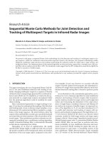
detecting abnormal vibrations in complex electromechanical systems. As shown in Fig.
1.2, the platform uses FFT and Envelope Analysis for processing each time-domain
healthy or faulty waveform collected from a healthy or faulty motor, ICA for extracting
the features to describe its signature as identified by Envelope Analysis and SVM for
classifying between healthy and faulty signatures. The in-depth description of each
component of the proposed platform will be given in remaining Chapters of this thesis.
15
Time-domain
vibration signals
Healthy
signals
Inner Race
Fault
Ball
Fault
Outer Race
Fault
FFT
Frequency-domain
vibration signals
Envelope
Analysis
ICA
Signals
Features
SVM
Motor Fault
Detection and Diagnosis
Fig. 1.2
Proposed automatic motor fault detection and diagnosis scheme
16
The thesis is therefore organized as follows:
Chapter 1 introduces the motivations and objectives of this thesis, reviews earlier work,
summarizes the contributions of this research, and shows the thesis outline.
Chapter 2 focuses on the structure and operation principle of induction motor, and
introduces the classification of induction motor faults. This thesis mainly studies the
detection and diagnosis of bearing fault, and additional source of vibration data sets are
from three different research organizations outside NUS: Bearing Data Center of Case
Western Reserve University, Vestas R&D Centre (Singapore) and SKF.
Chapter 3 describes the definition and principle of FFT-Envelope Analysis, which is
used to extract the feature of vibration signature of induction motors and
electromechanical systems. This system uses Fast Fourier Transformation to transform
the signal from time domain to frequency domain, and then uses Envelope Analysis to
reduce the noise influence and extract the fault signals. In the last Section of this Chapter,
it presents three groups of results by using FFT-En.
Chapter 4 focuses on the principle and implementation of Independent Component
Analysis (ICA). Due to the simple and reliability of ICA, this thesis adopts it as a feature
extraction method in induction machine condition monitoring and fault diagnosis field.
Furthermore, demonstrations on how FastICA works are presented at the end of this
Chapter.
The application of neural networks is widely employed to solve classification problem
for condition monitoring and fault diagnosis. Chapter 5 introduces a machine-learning
17