DESIGN OF ENERGY EFFICIENT WEARABLE ECG SYSTEM AND LOW POWER ASYNCHRONOUS MICROCONTROLLER
Bạn đang xem bản rút gọn của tài liệu. Xem và tải ngay bản đầy đủ của tài liệu tại đây (3.09 MB, 162 trang )
DESIGN OF ENERGY EFFICIENT WEARABLE
ECG SYSTEM AND LOW POWER
ASYNCHRONOUS MICROCONTROLLER
ZHANG DA REN
NATIONAL UNIVERSITY OF SINGAPORE
2012
Acknowledgements
First of all, I would like to thank my supervisors Prof. Lian Yong for his
encouragement and advice during my Master study. His guidance helps me a lot
through this work.
Secondly, I am grateful to my project team members, Mr. Xu Xiao Yuan, Chacko
John Deepu and Yang Tao for their continuous work and help on wearable ECG
system; and Mr. Xue Chao for his explaining of Asynchronous microcontroller part.
Thirdly, I would like to thank Mr. Teo Seow Miang and Ms. Zheng Huan Qun for
their technical support. My appreciation also goes to all my colleagues and friends of
the Signal Processing & VLSI lab. They are Zhang Jinghua, Zou Xiao Dan, Tan Jun,
Liew Wensin, Niu Tian Fang, Zhang Xiao Yang, Wang Lei, Zhang Zhe, Li Yong Fu,
Hong Yi Bin, Chen Xiaolei, Yang Zhenglin, Li Ti, Yu Heng and many others.
Lastly, but most importantly, I would like to dedicate this thesis to my beloved
parents Zhang Bao Chen and Xing Bin Wa. Their continuous encouragement and
support always give me confidence through my life.
i
Contents
Acknowledgements ....................................................................................................... i
Contents ........................................................................................................................ii
Summary....................................................................................................................... v
List of Tables ..............................................................................................................vii
List of Figures ........................................................................................................... viii
List of Abbreviations .................................................................................................. xi
Chapter 1 Introduction................................................................................................ 1
Chapter 2 Background ................................................................................................ 5
2.1 Wearable ECG system......................................................................................... 5
2.1.1 ECG introduction ....................................................................................... 5
2.1.2 ECG monitoring system Literature Review .............................................. 7
2.2 Asynchronous Circuit .......................................................................................... 9
2.2.1 Introduction ............................................................................................... 9
2.2.2 Asynchronous Handshake Protocols ....................................................... 11
2.3 Design Tools ..................................................................................................... 12
2.3.1 Hardware Development Tool .................................................................. 12
2.3.2 Firmware Development Tool................................................................... 13
2.3.3 Balsa for Asynchronous Circuit design ................................................... 14
Chapter 3 Wireless ECG Plaster .............................................................................. 16
ii
3.1 System Overview .............................................................................................. 16
3.2 Hardware ........................................................................................................... 17
3.2.1 ECG Acquisition chip BMDAV8............................................................ 18
3.2.2 Microcontroller ........................................................................................ 22
3.2.3 Zigbee RF transceiver ............................................................................. 24
3.2.4 Electrode and PET substrate.................................................................... 24
3.3 Firmware ........................................................................................................... 26
3.4 Graphical User Interface ................................................................................... 28
3.5 Design Verification ........................................................................................... 30
3.5.1 System Accuracy ...................................................................................... 30
3.5.2 System Reliability .................................................................................... 33
Chapter 4 Long Playing Cardio Recorder............................................................... 37
4.1 Overview of LPCR system ................................................................................ 37
4.2 Hardware ........................................................................................................... 40
4.2.1 Microcontroller ........................................................................................ 41
4.2.2 BMDAV7 ECG Acquisition Chip ........................................................... 44
4.2.3 NAND Flash…………………………………………………………….46
4.2.4 Blue Giga WT12..…………………...………………………………….48
4.3 Firmware design ................................................................................................ 49
4.3.1 Microcontroller and BMDAV7 ............................................................... 51
4.3.2 Microcontroller and FLASH ................................................................... 54
4.4 Graphical user Interface .................................................................................... 59
4.5 Design verification ............................................................................................ 59
4.5.1 ECG simulator testing ............................................................................. 60
4.5.2 Volunteer testing...................................................................................... 62
4.5.3 Long time battery testing ......................................................................... 64
Chapter 5 Wearable ECG system performance comparison ................................ 67
iii
Chapter 6 Asynchronous 8051 design ...................................................................... 69
6.1 Introduction ....................................................................................................... 69
6.1.1 Synchronous 8051 microcontroller ......................................................... 70
6.1.2 Asynchronous circuit design flow ........................................................... 71
6.2 Architecture of the Asynchronous 8051 ............................................................ 72
6.2.1 Overview of Asynchronous 8051 ............................................................ 72
6.2.2 8051 Asynchronous core ......................................................................... 73
6.3 Simulation Result .............................................................................................. 76
Chapter 7 Conclusion ................................................................................................ 78
Bibliography ............................................................................................................... 80
Appendix 1 LPCRV1 PCB design ............................................................................ 83
Appendix 2 Firmware Flash part ............................................................................. 87
Appendix 3 Asynchronouns 8051 core Balsa code ................................................ 100
iv
Summary
This work is about the design and implementation of energy efficient wearable
real time monitoring ECG system and a low power asynchronous 8051
microcontroller for biomedical sensor interface device. It is motivated by the
increasing awareness of Cardiac arrhythmias and coronary heart disease due to
population ageing and stressful modern life.
The hardware, firmware and graphical user interface are developed for energy
efficient wearable ECG system. There are two designs of wearable ECG system in
this work. The first design is a Wireless ECG Plaster prototype device. It is designed
for real-time monitoring of ECG in cardiac patients. The proposed device is light
weight (25 grams), easily wearable and can wirelessly transmit the patient’s ECG
signal to PC using ZigBee. The device has a battery life of around 26 hours while in
continuous operation, owing to a low power BMDAV8 ECG acquisition front end
chip. The prototype has been verified in clinical trials and variation is very low at
0.4% compared to the reference device. The second design is a Long Playing Cardio
Recorder system prototype. It is designed for 48 day long term ECG data recording,
and it is also a wearable device. It receives data from an ultra-low power ECG
acquisition chip. The data is stored into a 16G bit NAND flash. The system current
consumption could be less than 1.7mA from a 3.7V 650mAH Li-ion battery so it can
v
last for 30 days.
To further reduce the power consumption for wearable ECG system, a new design
of 3.3V to 1.0V voltage-scalable asynchronous 8051 Microcontroller is presented.
The asynchronous core of the proposed design is synthesized in the Balsa framework
using the dual-rail four-phase approach. With the same synchronous 8051
microcontroller instruction set which includes add, jump, and multiply operations
verified in simulation, the proposed AMS 0.35μm technology microcontroller
consumes about 40 µW at 1.0V supply.
vi
List of Tables
3.1
Hardware components………………………………………….................... 18
3.2
Performance Summary………………............................................. 21
3.3
Wireless ECG Plaster summary………………….......................................... 36
4.1
LPCR system Hardware major components....................................................... 40
4.2
Comparison between BMDAV7 and BMDAV8............................................. 45
4.3
BMDAV7 control bits........... ...... .......................................................... 53
4.4
BMDAV7 status bits........................................................................ 53
4.5
Control bits for FLASH reading and writing. ........................................... 56
4.6
Testing result For Average heart rate........... ............................................. 61
5.1
Comparison between other ECG monitoring systems....................................... 67
6.1
Comparison with other existing designs at 1.1V 0.35μm. ...................... 76
vii
List of Figures
2.1
The ECG signal......................................................... ................. 6
2.2
The normal ECG signal in one cardiac cycle……............................................ 6
2.3
José Antonio Gutiérrez Gnecchi’s ECG system....................................... 8
2.4
I – Jane Wang’s device overview........................................................... 9
2.5
Synchronous pipeline stages controlled by clock signal [8].................... 10
2.6
Asynchronous pipeline stages controlled by handshake signals............... 11
2.7
Handshake sequence of four-phase dual-rail data protocol............................. 12
2.8
Altium Designer. ……............................................................... 13
2.9
M P L A B I D E . . . . . . . . . . . . . . . . . . . . . . . . . . . . . . . . . . . . . . . . . . . . . . . . . . . . . . . . . . . . . 14
2.10 B a l s a . . . . . . . . . . . . . . . . . . . . . . . . . . . . . . . . . . . . . . . . . . . . . . . . . . . . . . . . . . . . . . . . . . . 15
3.1
S y s t e m O v e r v i e w . . . . . . . . . . . . . . . . . . . . . . . . . . . . . . . . . . . . . . . . . . . . . . . . . . . . . . . . . . . . . 16
3.2
System Architecture . ................................. .......................... 17
3.3
Architecture of Proposed ECG Acquisition Chip....................................... 19
3.4
Circuits for the ECG frond-end. ........................................................... 20
3.5
Concept of low power DRL circuit with direct common-mode extraction........ 20
3.6
C h i p m i c r o p h o t o . . . . . . . . . . . . . . . . . . . . . . . . . . . . . . . . . . . . . . . . . . . . . . . . . . . . . . . . . . . . 21
3.7
Microcontroller MSP430F2254 block diagram........................................ 23
3.8
Configuration for microcontroller and BMDAV8...................................... 23
3.9
CC240 Zigbee RF transceiver............................................................ 24
viii
3.10 Mash structure Electrode ……………........................................ 25
3.11 P l a s t e r s u b s t r a t e … . . . . . . . . . . . . . . . . . . . . . . . . . . . . . . . . . . . . . . . . . . . . . . . . . . . . . . . . . . . 25
3.12 Wireless ECG Plaster Top view ……......................................... 26
3.13 System Firmware Flow Chart............................................................ 27
3.14 GUI interface for PC ……………….................... ...................... 29
3.15 ECG data file saved from GUI……………………………………….. 29
3.16 The positions of the wireless ECG plaster and Holter……............................... 31
3.17 ECG Signal: Plaster Device Vs Reference Holter Monit.............................. 32
3.18 RR Interval histograms: ECG plaster Vs Reference Device........................... 33
3.19 SGH Clinical Trial set ……………….......................................... 34
3.20 Subject 2nd day morning Record ……………….......................................... 35
4.1
Long Playing Cardio Recorder (LPCR) Overview…........................ 38
4.2
LPCR ECG data collecting method ................. ....................... 39
4.3
Block Diagram of LPCR system……........................................... 40
4.4
P I C 1 8 F 4 6 J 5 0 b l o c k d i a g r a m . . . . . . . . . . . . . . . . . . . . . . . . . . . . . . . . . . . . . . 42
4.5
Pin configuration of PIC18F46J50 in LPCR system . ............... 43
4.6
BMDAV7 ECG Acquisition Chip . ......................................... 45
4.7
Pin configuration between BMDAV7 and PIC....................................... 46
4.8
MT29F16G08DAAWP Flash chip top view...................................................... 47
4.9
MT29F16G08DAAWP [15] Flash chip array organization.......................... 48
4.10 LPCRV1 PCB………......................................................................................... 49
4.11 Firmware state diagram...................................................................................... 50
4.12 ECG control sinals……………… …................................................................. 52
4.13 File structure of FLASH memory …................................................................. 55
4.14 MCU control block . .............................................................. 56
ix
4.15 F l a s h r e a d s e t t i n g . . . . . . . . . . . . . . . . . . . . . . . . . . . . . . . . . . . . . . . . . . . . . . . . . . . . . . . 58
4.16 Graphical User Interface…….. .......................................................................... 59
4.17 ECG simulator……………………………………………. ................ 60
4.18 30bpm, 60bpm, 90bpm ECG signal Simulation result. ................................. 61
4.19 The positions of the LPCRV1 and Welch allyn device. ......................... 62
4.20 Volunteer test result from Welch Allyn device and LPCR system................. 63
4.21 RR Interval histograms: LPCR system Vs Reference Device................. 64
4.22 Long time battery testing result (Battery voltage VS time)................. 65
6.1
8051 Microcontroller block diagram................................................... 71
6.2
Async 8051 Microcontroller [16] . ........................................... 73
6.3
Async 8051 core ……............................................................ 74
x
List of Abbreviations
A/D
Analog-to-digital
ADC
Analog-to-digital converter
AF
Aritrial fibrilation
ALU
Arithmetic and Logical Unit
AMS
AustriaMicroSystem
BPM
Bit per minute
CHD
Coronary heart disease
CMOS
Complementary metal-oxide-semiconductor
CISC
Complex Instruction Set Controller
DAC
Digital-to-analog converter
DRL
Right-leg driver
DSP
Digital signal processor
ECG
Electrocardiogram
EDA
Electronic design automation
HDL
Hardware description laguage
GDS
Graphical Database System
IF & ID
Instruction Fetch and Instruction Decoding
LEF
Libraray exchange file
LHP
Left-half-plane
xi
LPCR
Long time cardio recording
LPE
layout parasitic extraction
MIP
Million instruction per second
P&R
Placement and routing
ROM
Read only memory
S/H
Sample-and-hold
SOC
Silicaon on chip
SPICE
Simulation Program with Integrated Circuit Emphasis
USB
Universal Serial Bus
VLSI
Very Large Scale Integration
xii
Chapter 1
Introduction
Cardiac arrhythmias and coronary heart disease (CHD) constitute significant
public health burdens. Researches show that US$173 billion is spent every year for
treatment of heart related disorders in USA [1]. Atrial fibrillation (AF), a common
arrhythmia, afflicts nearly 9% of persons over 80 years old [2], and is associated with
increased stroke risk. Another arrhythmia, ventricular arrhythmia, can cause sudden
cardiac arrest. For heart related disorders, the chances of a total and fast recovery of
the patient are diminished by the late detection of the symptoms, which may cost
patient’s life. Early diagnosis presents an opportunity for preventive treatment.
However, many patients with cardiac arrhythmia or silent myocardial ischemia
remain undiagnosed and untreated, because abnormal electrocardiogram (ECG)
changes often occur sporadically and are easily missed. Hence, a better ECG
monitoring device is necessary.
In recent years, personal ECG monitoring medical device has attracted increasing
1
attention as it reveals to be a promising solution to the overwhelming demand in
healthcare industry due to population ageing. There are hundreds of portable ECG
monitoring systems in this market. The commonly used solutions like ambulatory
Holter systems are often bulky with many wires stuck on patient’s chest. The
operational life of the Holter is usually limited within 24 hours, and ECG data are
analyzed offline for diagnosis of the problem. One major shortcoming of the existing
ambulatory Holter systems is extremely low diagnostic yield at 10-13% [3]. In
addition, such devices are quite heavy and use traditional ECG electrodes, which are
not comfortable as there are multiple wires hanging over the body. And such devices
usually aren’t waterproof; therefore, the patient is expected to avoid water contact in
the area where the device is fixed. All these compromises patient’s comfort level and
affects his life style.
To avoid the limitations of such a kind of Holter device, the motivation of this
work is to present energy efficient wearable ECG monitoring system. There are two
phases for this work. In the first phase, a wireless ECG plaster prototype device is
designed for real-time monitoring of ECG in cardiac patients. This device, when
placed on patient’s chest, continually records single-lead ECG and wirelessly streams
it to a remote station for diagnosis. The skin contact electrodes have been printed on
flexible substrates with consideration for easy wearability. A highly integrated, low
power chip with low noise amplifier, ADC and low pass filters were developed inorder to reduce the power consumption and the number of discrete IC components.
In the second phase, another ECG monitoring device, Long Playing Cardio
2
Recording Version 1 (LPCRV1) system is designed. It can store 48 days ECG data. It
is designed for special requirement of long time ECG recording. The system still
keeps the advantage of light weighted and smaller in size from Wireless ECG Plaster.
Its firmware can maintain ultra low power consumption when huge data reading and
writing in order for long term used. The version 1 is the first version of Long Playing
Cardio Recording system. In this version, device uses traditional ECG lead contacts to
collect ECG signal instead of comfortable substrate. The focus of this version is low
power, long time playing and large ECG data recording in NAND Flash.
In addition, the microcontroller is a significant source of power consumption unit.
In order to further reduce the power consumption of the wearable ECG monitoring
system above, a microcontroller which consumes less power is desired.
Therefore,
this work also aims to design a new version of low-power asynchronous 8051
microcontroller based on previous work. This microcontroller works as a local
processing and control unit in a bio-medical sensor interface block which is powered
by batteries. It follows the structure of a standard synchronous 8051 microcontroller
invented by Intel, so firmware developer can use it easily. The asynchronous core of the
proposed design is synthesized in the Balsa framework using the dual-rail four-phase
approach. Furthermore, the core’s structure adopts No pipeline structure together with
Multiplication and Division block to improve power performance of asynchronous
8051 microcontroller.
The organization of this dissertation is as follows. In Chapter 1, introduction and
motivation of this work is introduced. Chapter 2 outlines a brief background of the
ECG and asynchronous circuit design. Chapter 3 and 4 elaborates Wireless ECG
3
Plaster and Long Playing Cardio Recording system individually. In Chapters 5, the
wearable ECG system comparison will do some performance analysis here. Chapter 6
details a new design for low power asynchronous 8051 microcontroller which is
designed for further reduce the power consumption of wearable ECG system in the
future. Chapter 7 concludes the work.
The Wireless ECG plaster of this work was accepted by the Biomedical Circuits
and Systems Conference (BioCAS), 2011 [4].
4
Chapter 2
Background
2.1 Wearable ECG system
2.1.1 ECG introduction
Electrocardiography (ECG) is an interpretation of the electricity activity of the
heart over a period of time, as detected by electrodes attached to the outer surface of
the skin and recorded by a device external to the body. Generally speaking, the ECG
signal shown in Figure 2.1 can reflect the electrical activities of a person’s heart over
time. Not only does it reflect his or her heartbeat, but also it provides greater insight to
the detailed biological activities of the heart. Because it can be obtained through
simple and nonintrusive procedures, the ECG signal has been one of the most
sophistically studied and widely used indicators for diagnosing heart diseases.
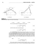
Based on the early studies on dogs in the 1950s and the latter similar studies on
the human heart in the 1970s, it is commonly accepted that the ECG signal is
essentially generated from the propagation of dipole wave fronts across the heart
tissue that originate from the depolarization and repolarization processes in the heart
5
cells.
Figure 2.1: The ECG signal
Figure 2.2: The normal ECG signal in one cardiac cycle.
6
Figure 2.2 depicts one cycle of the typical ECG signal obtained and recorded on
the standard ECG paper. The deflections are named in alphabetic order as P wave,
QRS complex, T wave and U wave respectively. The various segments and intervals
are defined and used extensively in diagnoses.
The P wave corresponds to the atrial depolarization. The ventricular
depolarization occurs during the QRS complex. The repolarization of the atria also
takes place in this interval but is too small to be observed in the ECG. The T wave
forms when the ventricles repolarize from activation. The formation of the U wave is
not very clear yet, and it is normally seen in 50% to 75% of ECGs [5].
2.1.2 ECG monitoring system Literature Review
ECG monitoring system is for monitoring patient’s ECG status and recording the
data. The basic requirement for telemetric ECG recording system, especially for a
portable/wearable one, is ultra-low power consumption. The ultra slim rechargeable
batteries manufactured for good portability today usually have only a few hundred
mAh of capacity. To operate the ECG device for weeks, the average current
consumption thereby should be strictly controlled within mA range. Because the
majority of the current has to go to the telemetry or storage circuit, the sensor
interface module can only share some tens of µA or even lower. Fortunately, the
sensor interface deals with low frequency and narrow bandwidth signals with medium
dynamic range accuracy, which makes such low current consumption feasible.
There are several researches for portable ECG recording system. José Antonio
7
Gutiérrez Gnecchi proposed an Ambulatory Electrocardiogram Recorder [6], the
ECGITM04. The 3-wire ECG monitoring device complies with several specifications:
low-power consumption (battery operated), on-line graphics display, 7-days
continuous data logger, patient electrical safety, minimal signal processing operations
to facilitate the identification of cardiac arrhythmia patterns and a JTAG
programming port so that the device can be updated without changing the data
acquisition hardware. The system can maintain long time operation, but the size of
this device is quite big. Patient may feel uncomfortable when wearing it.
Figure 2.3: José Antonio Gutiérrez Gnecchi’s ECG system
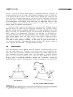
I – Jane Wang proposed a wearable mobile electrocardiogram monitoring system
[7] for long-term ECG monitoring. The wearable ECG acquisition device integrated
with dry foam electrodes and the ECG acquisition module was designed for long-term
ECG monitoring in daily life. Moreover, the ECG acquisition module is small-volume,
wireless and low-power consumption. And based on SMS communication technology,
patients can monitor their ECG anywhere in the globe if they are under the coverage
8
of GSM cellular network. The system is good in function but has a drawback that it
has to use large capacity battery in order to maintain long time monitoring. In addition,
dry foam electrodes are not weather proof.
Figure 2.4: I – Jane Wang’s device overview
2.2 Asynchronous Circuit
2.2.1 Introduction
The difficulty to find low power consumption is one of the crucial concerns for
portable ECG monitoring system design. Otherwise, the battery cannot last very long
time. The microcontroller, which is a significant source of power consumption for
central control block, should have the desirable characteristic of low-power
consumption. Hence, a technique for low power consumption design is needed.
Nowadays, most of the commercial digital designs are synchronous in nature. In
9
such circuits, there is usually a global clock signal which controls and synchronizes
the data movement from one register to another. However, the power consumption of
the clock tree constitutes a significant amount especially for low-power digital
designs. Consequently, there is an increasing research interest in the field of
asynchronous circuits over the years especially in the academic arena. Asynchronous
circuits are fundamentally different from synchronous circuits in the way that there is
no global clock signal present. Instead, asynchronous circuits make use of
handshaking signals, which acts as local clocks that are not in phase and with varying
period, to perform the controlling and synchronization of data movement as illustrated
by Figure below. In this way, the registers in asynchronous circuits are only clocked
where and when needed by the handshake signals.
Figure 2.5: Synchronous pipeline stages controlled by clock signal [8]
10
Figure 2.6: Asynchronous pipeline stages controlled by handshake signals
The main difference between synchronous circuits and asynchronous circuits lies
in the data synchronization and communication method adopted. Compare to
synchronous circuits, asynchronous circuits have several advantages. Firstly,
asynchronous does not have clock skew problem, the absence of a global clock signal
eliminates the clock skew problem faced in synchronous circuits. Secondly,
asynchronous circuit power consumption for is lower than synchronous circuit.
Absence of the clock tree in asynchronous circuits leads to practically zero stand-by
power consumption when the circuits are idle. For some synchronous circuits with
special sleep mode operation where the clock oscillator is turned off when the sleep
mode is activated, they can also achieve practically zero stand variations in supply
voltages and fabrication process. Timing assumption is based on matched delays for
bundled data protocol, and for asynchronous circuits that adopt the dual-rail protocol,
the insensitive or completely delay insensitive.
2.2.2 Asynchronous Handshake Protocols
In this project, the dual-rail four phase protocol is used to synthesize the
asynchronous core of the 8051 microcontroller. A short brief is introduced here
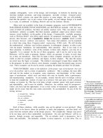
For a 4-phase dual-rail protocol, there is always an empty state in-between two
valid data. The handshake sequence is illustrated by Fig. 2.7 [8] and goes as follows:
1. The sender issues a valid data on the data bus, 2. the receiver sets the acknowledge
line to logic 1 once it captures the valid data on the data bus, 3. the sender then issues
11
an empty data on the data bus after capturing a logic 1 in the acknowledge line, 4. the
receiver accordingly lowers the acknowledge line upon detecting an empty data on the
data bus, completing one handshake cycle.
.
Figure 2.7: Handshake sequence of four-phase dual-rail data protocol
This protocol is very robust as it is insensitive to the delays involved in the wires
connecting the two communicating parties. As it’s so robust, voltage supply can be scaled
down for the circuit design which use this protocol. Another reason to choose this
protocol is that Balsa system can only support dual-rail four phase protocol in current
version. In this work, asynchronous 8051 microcontroller adopts this protocol.
2.3 Design Tools
There are several design tools for implement Wearable ECG system and
Asynchronous circuit.
2.3.1 Hardware Development Tool
12