Cross layer design for communication systems
Bạn đang xem bản rút gọn của tài liệu. Xem và tải ngay bản đầy đủ của tài liệu tại đây (802.85 KB, 148 trang )
CROSS-LAYER DESIGN FOR
COMMUNICATION SYSTEMS
VINEET SRIVASTAVA
NATIONAL UNIVERSITY OF SINGAPORE
2004
CROSS-LAYER DESIGN FOR
COMMUNICATION SYSTEMS
VINEET SRIVASTAVA
B.Eng(Hons.), NUS
A THESIS SUBMITTED
FOR THE DEGREE OF MASTER OF ENGINEERING
DEPARTMENT OF ELECTRICAL AND COMPUTER ENGINEERING
NATIONAL UNIVERSITY OF SINGAPORE
2004
Acknowledgements
First and foremost, a big thanks to my supervisor, Dr. Mehul Motani. He always
allowed me the room and time to think and explore on my own and never ever
forced his thoughts or ideas on me. At the same time, his comments and pointed
questions kept me on course and inspired me to strive for clear logical thinking
and expression. Thank you, Mehul—your friendly guiding influence has been a
wonderful initiation into the world of research for me.
This work was conducted on a part-time basis, along with my full-time
employment at Institute for Infocomm Research (I2 R). I thank my colleagues
at I2 R for their understanding and support throughout my candidature.
I also thank my parents, friends and relatives for providing me the support
and encouragement as I undertook my dip into the world of research. The somewhat philosophical discussions with my brother Puneet helped me stay focused
amidst the inevitable uncertainty that a research pursuit offers. Words of thanks
are also due to fellow students—in particular Hoang Anh Tuan, Lawrence Ong
and Yap Kok Kiong—for the numerous stimulating and useful discussions and
suggestions. I also acknowledge the anonymous reviewers of my publications,
for their comments have helped me greatly to refine my research focus. Similarly, the comments from the examiners of the first draft of my thesis helped
me to significantly improve the clarity of this thesis.
Finally, and most importantly, this work would not have been possible if
not for the unflinching love and encouragement from my lovely wife, Nidhi. Her
patience and understanding have meant a whole world to me.
i
Contents
Acknowledgements
i
List of Figures
vi
List of Tables
ix
List of Abbreviations
x
Summary
xii
1 Introduction
1.1
1.2
Growing proliferation of wireless networks . . . . . . . . . . . .
1
1.1.1
Two types of wireless networks . . . . . . . . . . . . . .
2
What is unique about wireless networks? . . . . . . . . . . . . .
2
1.2.1
The concept of a link . . . . . . . . . . . . . . . . . . . .
3
1.2.2
The broadcast nature of the wireless channel . . . . . . .
4
1.2.2.1
The problem of power control . . . . . . . . . .
6
1.2.2.2
Theoretical limit . . . . . . . . . . . . . . . . .
7
1.2.2.3
Possibility of node cooperation . . . . . . . . .
8
Fluctuations in channel quality . . . . . . . . . . . . . .
8
1.2.3
1.2.3.1
1.3
1
Should fading only be fought? . . . . . . . . . .
10
1.2.4
Other implications of mobility . . . . . . . . . . . . . . .
12
1.2.5
Device energy limitations . . . . . . . . . . . . . . . . . .
12
Layered architectures . . . . . . . . . . . . . . . . . . . . . . . .
13
ii
1.3.1
Defining architecture . . . . . . . . . . . . . . . . . . . .
13
1.3.2
The layered communication architecture . . . . . . . . .
15
1.3.3
Benefits of layering . . . . . . . . . . . . . . . . . . . . .
16
1.3.4
Important layered architectures . . . . . . . . . . . . . .
17
Layered architectures and wireless links . . . . . . . . . . . . . .
19
1.4.1
Wireless link as just another physical layer? . . . . . . .
21
1.4.2
The idea of cross-layer design . . . . . . . . . . . . . . .
22
1.5
Contributions of this thesis . . . . . . . . . . . . . . . . . . . . .
23
1.6
Organization of this thesis . . . . . . . . . . . . . . . . . . . . .
26
1.4
2 Cross-Layer Design: A survey and the road ahead
27
2.1
Introduction . . . . . . . . . . . . . . . . . . . . . . . . . . . . .
27
2.2
Understanding Cross-Layer Design . . . . . . . . . . . . . . . .
30
2.2.1
A definition for Cross-Layer Design . . . . . . . . . . . .
30
2.2.2
Cross-Layer Design: A historical context . . . . . . . . .
31
2.3
General motivation for Cross-layer design . . . . . . . . . . . . .
32
2.4
Cross-Layer Design: a taxonomy . . . . . . . . . . . . . . . . . .
33
2.4.1
Creation of new interfaces . . . . . . . . . . . . . . . . .
35
2.4.1.1
Upward information flow . . . . . . . . . . . . .
35
2.4.1.2
Downward information flow . . . . . . . . . . .
37
2.4.1.3
Back and forth information flow . . . . . . . . .
37
2.4.2
Merging of adjacent layers . . . . . . . . . . . . . . . . .
39
2.4.3
Design coupling without new interfaces . . . . . . . . . .
39
2.4.4
Vertical calibration across layers . . . . . . . . . . . . . .
40
Proposals for new architectures . . . . . . . . . . . . . . . . . .
41
2.5.1
Allowing the layers to communicate . . . . . . . . . . . .
42
2.5.2
A shared database across the layers . . . . . . . . . . . .
43
2.5.3
Completely new abstractions . . . . . . . . . . . . . . . .
43
A unified platform . . . . . . . . . . . . . . . . . . . . . . . . .
44
2.6.1
44
2.5
2.6
Coupling between Network and MAC layers . . . . . . .
iii
2.7
2.8
2.9
2.6.2
Channel knowledge at the MAC layer . . . . . . . . . . .
45
2.6.3
Explicit notifications to the Transport layer . . . . . . .
45
2.6.4
Other couplings . . . . . . . . . . . . . . . . . . . . . . .
46
Open Challenges . . . . . . . . . . . . . . . . . . . . . . . . . .
46
2.7.1
The role of the physical layer . . . . . . . . . . . . . . .
47
2.7.2
The right communication model . . . . . . . . . . . . . .
48
2.7.3
Co-existence of cross-layer design proposals . . . . . . . .
48
2.7.4
When to invoke a particular cross-layer design? . . . . .
49
2.7.5
Standardization of interfaces . . . . . . . . . . . . . . . .
50
New opportunities for Cross-Layer Design . . . . . . . . . . . .
51
2.8.1
The broadcast nature of the wireless medium
. . . . . .
51
2.8.2
Types of co-operation schemes . . . . . . . . . . . . . . .
52
2.8.3
Planned Co-operation . . . . . . . . . . . . . . . . . . .
53
2.8.4
Unplanned Co-operation . . . . . . . . . . . . . . . . . .
55
2.8.5
Summing up . . . . . . . . . . . . . . . . . . . . . . . . .
56
Conclusions . . . . . . . . . . . . . . . . . . . . . . . . . . . . .
57
3 Physical Layer Design with a Higher Layer Metric in Mind
58
3.1
Introduction . . . . . . . . . . . . . . . . . . . . . . . . . . . . .
58
3.2
The background . . . . . . . . . . . . . . . . . . . . . . . . . . .
61
3.2.1
Physical Layer Processing . . . . . . . . . . . . . . . . .
61
3.2.1.1
Digital Modulation . . . . . . . . . . . . . . . .
62
3.2.1.2
The significance of finite bandwidth . . . . . . .
64
3.2.1.3
Forward Error Correction . . . . . . . . . . . .
65
3.2.1.4
Error probability performance . . . . . . . . . .
67
3.2.2
Link Layer Processing . . . . . . . . . . . . . . . . . . .
68
3.2.3
Delay results on M/G/1 queues . . . . . . . . . . . . . .
71
System Model . . . . . . . . . . . . . . . . . . . . . . . . . . . .
72
3.3.1
Description of the model . . . . . . . . . . . . . . . . . .
72
3.3.2
A discussion of the assumptions . . . . . . . . . . . . . .
73
3.3
iv
3.3.3
3.4
3.5
Metric of interest . . . . . . . . . . . . . . . . . . . . . .
74
A Modified ARQ System . . . . . . . . . . . . . . . . . . . . . .
76
3.4.1
Impact of α and β on Average Service Time . . . . . . .
76
Relating to Physical Layer Processing . . . . . . . . . . . . . . .
77
3.5.1
Forward Error Correction . . . . . . . . . . . . . . . . .
77
3.5.1.1
Numerical example . . . . . . . . . . . . . . . .
78
Digital Modulation . . . . . . . . . . . . . . . . . . . . .
81
Average Delay . . . . . . . . . . . . . . . . . . . . . . . . . . . .
81
3.6.1
Average Delay in the Modified System . . . . . . . . . .
82
Relating to Physical Layer Processing . . . . . . . . . . . . . . .
86
3.7.1
Forward Error Correction . . . . . . . . . . . . . . . . .
86
3.7.1.1
Numerical example . . . . . . . . . . . . . . . .
87
Digital Modulation . . . . . . . . . . . . . . . . . . . . .
89
3.7.2.1
Numerical example . . . . . . . . . . . . . . . .
90
Conclusions . . . . . . . . . . . . . . . . . . . . . . . . . . . . .
91
3.5.2
3.6
3.7
3.7.2
3.8
4 Queueing Meets Coding
93
4.1
Introduction . . . . . . . . . . . . . . . . . . . . . . . . . . . . .
93
4.2
Known results for linear block codes . . . . . . . . . . . . . . . .
94
4.2.1
Fundamental Concepts . . . . . . . . . . . . . . . . . . .
95
4.2.1.1
Terminology . . . . . . . . . . . . . . . . . . . .
95
4.2.1.2
The Generator and the Parity-Check matrices .
96
4.2.1.3
Hamming sphere . . . . . . . . . . . . . . . . .
97
4.2.2
Error Correction Capability . . . . . . . . . . . . . . . .
98
4.2.3
Bounds on Code Size . . . . . . . . . . . . . . . . . . . .
99
4.2.3.1
Numerical Illustration . . . . . . . . . . . . . . 103
4.2.4
Asymptotic forms of bounds on Code Size . . . . . . . . 104
4.2.5
The sphere-packing bound . . . . . . . . . . . . . . . . . 106
4.3
STI Codes: A brief recap . . . . . . . . . . . . . . . . . . . . . . 109
4.4
Existence of full-length STI codes . . . . . . . . . . . . . . . . . 109
v
4.4.1
The preliminaries . . . . . . . . . . . . . . . . . . . . . . 109
4.4.2
The VG bound argument . . . . . . . . . . . . . . . . . . 112
4.4.3
The sphere-packing bound argument . . . . . . . . . . . 114
4.4.4
Numerical example . . . . . . . . . . . . . . . . . . . . . 114
4.5
Large packet length . . . . . . . . . . . . . . . . . . . . . . . . . 116
4.6
Conclusions . . . . . . . . . . . . . . . . . . . . . . . . . . . . . 118
5 Conclusions and Further Work
119
Bibliography
122
vi
List of Figures
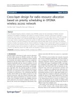
1.1
An example network configuration. Several network topologies
are possible for the same physical placement of nodes. . . . . . .
1.2
3
An implication of the broadcast nature of the medium. Transmission from node 3 to node 4 cannot take place if transmission from
node 1 to node 2 is ongoing, assuming omni-directional antennas.
5
1.3
An illustration of a hierarchical architecture. . . . . . . . . . . .
14
1.4
The reference model for the layered architecture. . . . . . . . . .
20
2.1
Illustrating the different kinds of cross-layer design proposals.
The rectangular boxes represent the protocol layers. . . . . . . .
34
2.2
Proposals for architectural blueprints for wireless communications. 41
2.3
A relay channel. The source’s transmission is heard by both the
relay and the destination. The relay can then transmit some
additional data that can help the destination decode the source’s
message. . . . . . . . . . . . . . . . . . . . . . . . . . . . . . . .
2.4
51
Data transfer with node co-operation in an ad-hoc network. Node
A is the source and Node G is the destination. Nodes B, D and
E act as relays co-operating with nodes A, C and F respectively.
2.5
3.1
54
An assessment of the architecture violations needed to allow protocols that rely on planned co-operation in the network. . . . . .
56
The system model under consideration. . . . . . . . . . . . . . .
73
vii
3.2
Timing diagram of the ARQ System. The packet in the illustration requires one retransmission. . . . . . . . . . . . . . . . . . .
3.3
Pictorial Representation of Theorem 3.1. A code is an STI code
if and only if it falls in the shaded region. . . . . . . . . . . . . .
3.4
75
80
Rc , pc regions where the coded systems exhibit higher and lower
average delay compared to uncoded systems. No immediate conclusion can be made about the codes falling in the unshaded region. 87
3.5
The average delay performance of the different systems. As expected, System A exhibits a higher average delay as compared
to the uncoded system and System C exhibits a lower average
delay. System B also exhibits a higher delay compared to the
uncoded system, though this could not be predicted from the
analysis. . . . . . . . . . . . . . . . . . . . . . . . . . . . . . . .
3.6
88
The simulated delay performance against λ. As expected, the
QPSK system exhibits a higher average service time as well as a
higher average delay compared to the BPSK system. . . . . . .
4.1
91
Given n = 63, the various bounds on t as k takes on different
values. . . . . . . . . . . . . . . . . . . . . . . . . . . . . . . . . 103
4.2
Asymptotic Hamming and Varshamov-Gilbert bounds . . . . . . 106
4.3
The only value where P > g(P ) is P = 5. . . . . . . . . . . . . . 115
4.4
πSP (P ) > f (P ) for all P except P = 5 and P = 9. Hence, if
(P = 5) and (P = 9), then no (21 + P, 21) STI code exists. . . . 116
viii
List of Tables
1.1
Network functionality performed by the different layers in figure
1.4 . . . . . . . . . . . . . . . . . . . . . . . . . . . . . . . . . .
3.1
20
T¯s′ values for the three coded systems. The average service time
for the uncoded system is T¯s = 0.123s. . . . . . . . . . . . . . .
ix
80
List of Abbreviations
ABBREVIATIONS
FULL EXPRESSIONS
ARQ
Automatic Repeat Request
AWGN
Additive white Gaussian Noise
BCH
Bose-Chaudhary Hocquenghem
BPSK
Binary Phase-Shift Keying
BSC
Binary Symmetric Channel
CDMA
Code-Division Multiple Access
CLASS
Cross-Layer Signalling Shortcuts
CTS
Clear to Send
DARPA
Defense Advanced Research Project Agency
FCFS
First-Come First-Serve
FDMA
Frequency Division Multiple Access
FEC
Forward Error Correction
GF
Galois Field
GSM
Global System for Mobile Communications
HDR
High Data Rate
IEEE
Institute of Electrical and Electronics Engineers
IP
Internet Protocol
ISO
International Standards Organization
JOCP
Joint Optimal Congestion Control and Power Control
x
LAN
Local Area Network
MAC
Medium Access Control
MPR
Multi-Packet Reception
MQAM
M-ary Quadrature Amplitude Modulation
NAK/NACK
Negative Acknowledgment
OAR
Opportunistic Auto Rate
OSI
Open Systems Interconnection
Probability Density Function
PHY (Layer)
Physical (Layer)
PK formula
Pollazcek-Khinchin formula
QPSK
Quadrature Phase-Shift Keying
RBAR
Receiver Based Auto Rate
RSSI
Received Signal Strength Indicator
RTS
Request to Send
SIR
Signal-to-Interference Ratio
SINR
Signal-to-Interference-and-Noise Ratio
SNR
Signal-to-Noise Ratio
STI
Service-Time Improving
TCP
Transmission Control Protocol
VG (bound)
Varshamov-Gilbert (bound)
xi
Summary
Recent years have witnessed a widespread proliferation of wireless communication networks around the world. Wireless networks, and wireless communications in general, present several engineering challenges that were not present
in their predecessor wired networks. At the same time, wireless networks—in
particular ad-hoc wireless networks—offer certain modalities of communications
that were just not possible in the wired networks. Such peculiarities of wireless communication networks are ushering in new paradigms for communication
protocol design that better address the challenges and opportunities created by
the wireless medium. This thesis looks at one such emerging paradigm termed
as cross-layer design. The main idea behind cross-layer design is to allow enhanced dependence and information sharing between the different layers of the
protocol stack. This is in contrast with the layered architectures that have been
the cornerstone of data network design and development. In this thesis, we
attempt to understand the cross-layer design methodology in more detail. We
take stock of the existing work in this area, distill some key insights and spell
out some of the open challenges.
After discussing in detail about the different aspects of cross-layer design,
we present an instance of cross-layer design involving the link layer and the
physical layer. In particular, we study the design of physical layer for a pointto-point communication system with the link layer average service time as our
metric of interest. We come up with necessary and sufficient conditions on the
parameters of specific physical layer processes like Forward Error Correction
xii
and digital modulation such that the link layer average service time is favorably
affected. We also study the impact of physical layer processing on the link layer
average delay (sum of the average service time and the average queueing delay),
assuming a Poisson arrival process.
Finally, we focus on forward error correction and merge the necessary and
sufficient condition for improving the link layer average service time mentioned
above with the Varshamov-Gilbert (VG) bound and the Sphere-packing bound,
which are well-known coding theoretic results. Doing so enables us to study
the existence of Service-Time Improving (STI) codes. By STI codes, we mean
forward error correcting codes that reduce the average service time with respect
to uncoded transmission for a fixed symbol rate and constellation size. We
also explore the asymptotic case of large packet length and determine sufficient
conditions for the existence of STI codes in this regime using the asymptotic
form of the VG bound and the channel capacity theorem.
In summary, this thesis starts with a qualitative exploration of the various
facets of cross-layer design. To the best of our knowledge, the methodology of
cross-layer design has not been looked at so closely elsewhere. We then move
on to apply some of the ideas to a specific scenario of a point-to-point communication system. Quantitative guidelines for physical layer processing with a
higher layer metric in mind are developed for the system under consideration.
These guidelines can be of practical importance. The application of coding theory ideas yields results that are more theoretical in nature but represent the
application of ideas from two different disciplines—queueing theory and coding
theory—in solving a communications problem.
xiii
Chapter 1
Introduction
1.1
Growing proliferation of wireless networks
Recent years have witnessed a sharp increase in network deployments that rely
on some form of wireless communications. The familiar and almost ubiquitous
cellular mobile phone networks are an example. The sharp rise in the proliferation of mobile phones and mankind’s increasing dependence on them is evident
even to a casual observer. In his book “The Smart Mobs” [1], author Howard
Rheingold talks about the social transformations being brought about by the
increasing pervasiveness of mobile phones. The fact that Rheingold substantiates his case by citing examples of events that have already happened speaks
for the increasing proliferation of mobile phones around the world.
There has also been an increase in the deployments of wireless data networks,
for example those based on the IEEE 802.11b standard [2]. Such networks are
appearing in offices and commercial establishments like airports and restaurants.
At the same time, primarily voice oriented networks like those based on Global
System for Mobile communications (GSM) are being beefed up to handle data
traffic [3, page 23]. In fact, if the growth in the wireless device subscriber
1
base and the increasing popularity of the Internet are put together, it can be
projected that wireless networks are likely to be an integral part of the Internet
in the future [3, page 18].
1.1.1
Two types of wireless networks
Wireless networks can broadly be divided into two categories, namely, cellular
networks and ad-hoc networks. Cellular networks are formed when a certain
geographical area is divided into cells, whereby each cell is served by a central
controller node [4, page 6]. The voice network such as GSM is an example of
a cellular network. The master node in the GSM network is usually called the
base station. Most data networks today (for example the wireless local area
networks) also follow the cellular design principle, whereby the mobile nodes
communicate with a central node that is termed as an Access Point [2].
Wireless ad-hoc networks differ markedly from their cellular counterparts
in that there is no fixed infrastructure in the network [3, page 401]. That is,
there are no nodes that serve as the base-stations. Hence, all the network tasks
need to be completed by the nodes themselves in a distributed manner. Adhoc wireless networks have found military applications, where deployment of
infrastructure is not possible.
1.2
What is unique about wireless networks?
The growth in the popularity and pervasiveness of wireless networks is making
wireless networks the center stage for the research and development activities in
the field of data networking. In this section, we look at some aspects of wireless
links and wireless networks that set them apart from their wired counterparts.
We also highlight how the fundamental nature of the wireless channel offers
2
Physical Placement
of Nodes
1
d
2
11 Mbps
2
d
3
d
4
Example topology 1
1
11Mbps
3
11Mbps
4
Example topology 2
5.5 Mbps
1
11 Mbps
2
11Mbps
3
11Mbps
4
5.5 Mbps
Figure 1.1: An example network configuration. Several network topologies are
possible for the same physical placement of nodes.
some new modalities of communication that were not available in the wired
networks.
1.2.1
The concept of a link
One of the most pertinent differences between wired communications and wireless communications concerns the concept of a communication link. A communication link between two nodes implies that the nodes in question can communicate directly with each other. In the wired world, there is a clear-cut concept
of a communication link. There is a communication link between two nodes
3
if and only if there is a wire connecting the two nodes. On the other hand,
there is no such notion of a communication link between two wireless nodes.
Whether or not a link exists between two nodes depends on a host of factors,
most notably, the signal-to-interference-and-noise ratio (SINR) at the receiver.
To see an implication, let us consider a hypothetical example network formed
by communication nodes in figure 1.1. Without loss of generality, let us focus on
node 1. The nodes with which node 1 can communicate directly (in a single hop)
depends upon the transmission power and the physical layer signal processing. It
is also possible that for a given transmit power, node 1 can communicate directly
with all the other three nodes, albeit at different data rates. Hence, several
network topologies are possible for the same physical placement of the nodes,
depending upon the transmission power and the physical layer characteristics.
In fact, the network topology depends not just on the transmission power of one
node. It is the interplay between the transmission powers of all the nodes and
the interference that they cause to the other nodes that determines the possible
network topologies. Contrast this with a wired network, where the network
topology is determined solely by the physical connection of the wires between
the nodes.
1.2.2
The broadcast nature of the wireless channel
One of the peculiarities of wireless communications is that the communications
are inherently broadcast in nature. Basically, a wireless transmitting node simply radiates power in form of electro-magnetic waves. With an omni-directional
antenna, the radiated power would propagate in all directions, and can potentially be received by all nodes that are within a certain distance from the
transmitting node.
4
Ongoing
transmission
1
2
3
4
This transmission cannot be
started until the ongoing
transmission gets over.
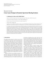
Figure 1.2: An implication of the broadcast nature of the medium. Transmission
from node 3 to node 4 cannot take place if transmission from node 1 to node 2
is ongoing, assuming omni-directional antennas.
Let us now see an implication of the broadcast nature of the wireless channel.
Consider the hypothetical network situation in figure 1.2. Let us say that at
a given time instance, node 1 is sending data to node 2. This transmission,
in effect, precludes the possibility of any communication from node 3 to node
4. This is because if node 3 were to start its transmission, there would be
interference at node 2, resulting in the transmission from node 1 to node 2 to
be lost. Contrast this with a scenario where the nodes are connected to each
other with physical wires. In this case, simultaneous transmissions from node 1
to node 2 and node 3 to node 4 could continue.
The problem that we mentioned above is in fact the well known hiddenterminal problem [5]. A possible solution to the problem is the familiar Requestto-Send (RTS) and Clear-to-Send (CTS) handshake prior to the transmission
of a packet [5]. In the RTS-CTS handshake, a node that has a data packet
to send first sends out an RTS packet that is received by all the node that lie
in the vicinity of the sending node. If the intended recipient receives the RTS
packet and is ready to receive a data packet, it responds by sending out a CTS
packet. It is only after this handshake between the transmitting node and the
5
intended receiver that the transmission of the data packets starts. Note that
since both RTS and CTS packets are heard by all the nodes, packet collisions
can be prevented. For instance, in the example network in figure 1.2, the CTS
packet from node 2 (when node 2 responds to the RTS packet from node 1) will
be heard by node 3. As a result, node 3 will not attempt any transmission to
node 4 till the transmission from node 1 to node 2 is going on. It should be added
that packet collisions are still possible, even with the RTS-CTS handshake. See
[6] and the references therein for details.
An interesting observation about the RTS-CTS handshake above is that the
RTS-CTS handshake itself relies on the broadcast nature of the wireless channel.
Thus, in some sense, it makes use of the same capability that it tries to fight!
1.2.2.1
The problem of power control
The lack of a clear-cut definition of a communication link and the broadcast
channel throw up the problem of power control in wireless ad-hoc networks.
Basically, as discussed earlier, the transmission powers of the nodes determine
the network topology. If the transmission powers of the nodes are large, all the
nodes can possibly reach each other in a single hop. However, the broadcast
nature of wireless communications means that a large transmission power also
leads to higher interference on the other nodes. Hence, despite employing large
powers, nodes may not be able to communicate with one another. On the
other hand, if the transmission powers employed by the nodes are too small,
the network might get fragmented. Hence, there is a need to perform power
control, which means adjusting the powers transmitted by the different nodes
in the network. This problem comes up as a result of the fundamental nature
of the wireless medium and has no clear counterpart in wired networks.
6
1.2.2.2
Theoretical limit
We now discuss some recent theoretical results regarding the data transporting
capacity of wireless ad-hoc networks. These results highlight both the unique
nature of the wireless medium as well as the innovative communication schemes
that can be employed on this medium.
Reference [7] considers the problem of computing the capacity of a wireless
ad-hoc network with fixed (stationary) nodes. Communication nodes are assumed to be scattered randomly on a unit disk and sources and destinations
are picked randomly. The nodes also have the capacity to act as relays. All the
nodes transmit at a certain fixed power. The main result in [7] is that as the
number of nodes is increased, the throughput per source-destination pair goes
to zero. This is despite optimal scheduling of transmissions that is assumed in
[7]. The primary factor resulting in a diminished throughput is the interference
that the nodes cause to one another, thanks to the broadcast nature of the
medium. An implication of the result in [7] is that very large scale wireless
ad-hoc networks may be infeasible.
Reference [8] introduces mobility to the model considered in [7]. That is, it
assumes that the nodes are capable of moving around in random motion. It is
then shown that if the delay constraints are loose, mobility in the network can
be used to obtain a constant throughput per source-destination pair, even as
the number of nodes becomes large. The main idea is that as the nodes move
around, the immediate neighborhood of the nodes changes with time. Thus, a
node can split its packet into several parts and transmit the parts to different
neighbors when they come close to itself. At a later time, the message can
be delivered to the ultimate destination by the intermediate nodes, when they
come close to the destination themselves. Thus, the actual transmission occurs
7
only between nodes that are close to each other.
The aforementioned results, in particular the latter result, underscore the
fact that “out-of-the-box” solutions for communications might need to be devised to make a viable usage of the wireless medium.
1.2.2.3
Possibility of node cooperation
The broadcast nature of the wireless channel also gives rise to an intriguing possibility of nodes cooperating with each other. Basically, when a node transmits
a packet, it can potentially be received by all its neighbors. These neighbors can
then cooperate in delivering the packet to the final destination. As an example,
consider [9] and the references therein, which deal with the possibility of user
cooperation in cellular networks. Clearly, such possibilities are also available in
ad-hoc wireless networks. In fact, even more interesting modes of node cooperation can be envisaged in wireless ad-hoc networks. For instance, a group of
nodes can collectively cancel interference for some other node [10]. Reference
[11] presents an information-theoretic analysis covering several such modalities
allowed by the wireless medium.
Such possibilities can potentially be used for communication over wireless
networks. We shall look at this more closely in Section 2.8. At this point, it
suffices to note that cooperation between users, as described above, could not be
realized easily in the wired networks. It is the broadcast nature of the wireless
medium that makes such possibilities feasible.
1.2.3
Fluctuations in channel quality
One unique feature of wireless communication links comes from the fact that
the quality of the channel can fluctuate with time. This happens when there
8
is relative motion between the source and the destination and/or the scatterers
in the medium [12, page 801]. As a result, the received SNR varies with time.
This is in sharp contrast to a wired link.
The fluctuation of received SNR can be seen to occur at two different time
scales [4, page 21]. The long-term effects [4, page 26] result in significant fluctuations in the average received SNR and occur due to a significant change
in the distance between the transmitter and the receiver during the course of
the communication session. Basically, for a fixed radiated power, the average
received power decays with distance. Thus, if the distance between the transmitter and the receiver changes appreciably, so does the average received power.
Mobile nodes can also temporarily move into areas that are inaccessible for the
radio waves, even though they lie within the coverage range of the network. An
example is the familiar disruption of mobile phone conversation when entering
elevators. This effect is usually referred to as shadowing.
On top of the long-term effects, there can also be fluctuation in the instantaneous received signal power. This effect is usually referred to as (short-term)
fading [4, page 31]. As a result of fading, the average SNR is not changed.
However, the instantaneous SNR undergoes rapid changes. The rapidity of the
fluctuations in the instantaneous SNR depends upon the relative speed between
the source and the destination—the higher the speed, the more rapid the fluctuations.
The effect of shadowing can be handled relatively easily by employing some
form of an automatic gain control at the receiver or with power control at the
transmitter, provided there is a feedback channel from the receiver back to the
transmitter. Hence, short-term fading is more interesting and we discuss it
below in more detail.
9
1.2.3.1
Should fading only be fought?
One approach of handling fading is to “fight” it. For instance, one could design
signal-processing algorithms to mitigate the effects of fading. Generally, this
involves making use of some form of diversity techniques (see for example [12,
page 821]).
When the time-variation of the channel caused by fading is seen from a
networking perspective however, the attitude towards fading tends to change
somewhat. On one hand, fading makes the communication difficult by increasing the required SNR for a certain performance (for example Eb /N0 of about
10 dB to achieve a bit-error-rate of 10−5 with BPSK modulation on an AWGN
channel vs. 44 dB on a flat Rayleigh fading channel [12, page 816]). On the
other hand, fading creates opportunities that can be exploited. Basically, as
[13] puts it, fading allows the physical channel to be viewed as a “packet pipe”
whose delay, rate and/or error probability characteristics vary with time. Contrast this with a wired communication channel whose characteristics remain
largely time-invariant. Reference [13] considers a buffered single user point-topoint communication system and proposes a rate and power adaptation policy
based on the fluctuations of the channel and the buffer occupancy. Reference
[14] considers a similar situation and also comes up with an optimal adaptive
policy that minimizes a linear combination of the transmission power and the
buffer overflow probability. Such adaptations are not meaningful on wired links
because the characteristics of the link do not vary with time.
Works such as [13] and [14] can be seen as solutions motivated from the
information theoretic idea of water-filling [15]. The key idea in water-filling is
to adapt the transmission power to the fading process, such that the signal is
transmitted at a higher power when the channel is in a good state and at a low
10