Decoupled maximum likelihood carrier frequency offset estimator for MIMO OFDM systems
Bạn đang xem bản rút gọn của tài liệu. Xem và tải ngay bản đầy đủ của tài liệu tại đây (506.84 KB, 75 trang )
Chapter 1
Introduction
Wireless communications technologies are now prevalent throughout today's society and
growing in demand. The whole world are planning and installing radio networks to
support communications requirements, the success of these networks may be driven by
the availability of the radio frequency spectrum. The radio frequency spectrum, a finite
natural resource, has greater demands placed on it every day. In an effort to make the
most efficient use of this resource, various technologies have been developed so that
multiple, simultaneous users can be supported in a finite amount of spectrum. This
concept is called "multiple access." To ensure profit grows parallel with the demand for
wireless technologies, manufacturers have had to develop methods of putting more users
in the same spectrum space. In this thesis, we focus on the discussion of Orthogonal
Frequency Division Multiplex (OFDM), a multiple access technology which has drawn
increasing attention recently.
1.1
Advantage of OFDM Systems
Frequency division multiplexing (FDM) is a technology that transmits multiple signals
simultaneously over a single transmission path, such as a cable or wireless system. Each
signal travels within its own unique frequency range (carrier), which is modulated by the
data (text, voice, video, etc.).
OFDM spread spectrum technique distributes the data over a large number of carriers that
are spaced apart at precise frequencies. This spacing provides the "orthogonality" in this
1
technique which prevents the demodulators from seeing frequencies other than their own.
In a typical terrestrial broadcasting scenario, there are multipath-channels (i.e. the
transmitted signal arrives at the receiver using various paths of different length). Since
multiple versions of the signal interfere with each other (inter symbol interference (ISI)),
it becomes very hard to extract the original information. The “orthogonality” between
sub-carrier makes OFDM outperform other wireless systems in terms of high spectral
efficiency, resiliency to RF interference, and lower multi-path distortion. Due to these
benefits, OFDM systems have received increasing attention. There is a great interest in
using OFDM for high-speed wireless local area network applications. Development is
ongoing for wireless point-to-point and point-to-multipoint configurations using OFDM
technology. In a supplement to the IEEE 802.11 standard, the working group published
IEEE 802.11a, which outlines the use of OFDM in the 5.8 GHz band[42]. OFDM forms
the basis for the Digital Audio Broadcasting (DAB) and Digital Video Broadcasting
(DVB) standard in the European market. OFDM also forms the basis for the global
ADSL (asymmetric digital subscriber line) standard.
1.2
Advantage of MIMO-OFDM Systems
The major challenges in future wireless communications system design are increased
spectral efficiency and improved link reliability. The wireless channel constitutes a
hostile propagation medium, which suffers from fading (caused by destructive addition of
multipath components) and interference from other users. Diversity provides the receiver
with several (ideally independent) replicas of the transmitted signal and is therefore a
2
powerful means to combat fading and interference and thereby improve link reliability.
Common forms of diversity are time diversity (due to Doppler spread) and frequency
diversity (due to delay spread). In recent years the use of spatial (or antenna) diversity has
become very popular, which is mostly due to the fact that it can be provided without loss
in spectral efficiency. Receive diversity, that is, the use of multiple antennas on the
receive side of a wireless link, is a well-studied subject [4]. Driven by mobile wireless
applications, where it is difficult to deploy multiple antennas in the handset, the use of
multiple antennas on the transmit side combined with signal processing and coding has
become known under the name of space-time coding and is currently an active area of
research. The use of multiple antennas at both ends of a wireless link (multiple-input
multiple-output (MIMO) technology) has recently been demonstrated to have the
potential of achieving extraordinary data rates. The corresponding technology is known
as spatial multiplexing and yields an impressive increase in spectral efficiency.
The main motivation for using OFDM in a MIMO channel is the fact that OFDM
modulation turns a frequency-selective MIMO channel into a set of parallel frequency
MIMO channels. Besides spatial diversity, broadband MIMO channels offer higher
capacity and frequency diversity due to delay spread. Orthogonal frequency division
multiplexing significantly reduces receiver complexity in wireless broadband systems.
The use of MIMO technology in combination with OFDM, i.e., MIMO-OFDM [5,6,7],
therefore becomes an attractive solution for future broadband wireless systems.
3
MIMO-OFDM is a technology that uses multiple antennas to transmit and receive radio
signals. It allows service providers to deploy a Broadband Wireless Access (BWA)
system that has Non-Line-of-Sight (NLOS) functionality. Specifically, MIMO-OFDM
takes advantage of the multipath properties of environments using base station antennas
that do not have LOS.
The MIMO systems use multiple antennas to simultaneously transmit data, in small
pieces to the receiver, which can process the data flows and put them back together. This
process, called spatial multiplexing, proportionally boosts the data-transmission speed by
a factor equal to the number of transmitting antennas. In addition, since all data is
transmitted both in the same frequency band and with separate spatial signatures, this
technique utilizes spectrum very efficiently.
1.3
Problem in OFDM Systems
One of the arguments against OFDM is that, it is sensitive to synchronization errors.
There are two main kinds of synchronization errors: time symbol error and Carrier
Frequency Offset (CFO). In this thesis, only the effect of CFO is studied.
CFO is the difference between the carrier frequency of the received signal and the
frequency of the receiver oscillator. It is caused by the Doppler shift and oscillator
instabilities. There are two types of carrier frequency offset: Integer CFO and fractional
CFO. Carrier frequency errors result in a shift of the received signal’s spectrum in the
frequency domain. With the frequency errors as an integer multiple of the subcarrier
4
spacing, the subcarriers are still mutually orthogonal. But the received data symbols,
which are mapped to the OFDM spectrum, are in the wrong position in the demodulated
spectrum. Fractional CFO spills the energy over the subcarriers, resulting in loss of their
mutual orthogonality and hence causes inter-carrier interference(ICI).
Both SISO-OFDM and MIMO-OFDM systems suffer from the loss of orthogonality
between the sub-carriers due to CFO. CFO attenuates the desired signal, adds phase, and
reduces the signal to noise ratio (SNR)[8]. As a result, performance of the systems is
severely downgraded. Accurate carrier offset estimation and compensation is more
critical in OFDM communication systems than other modulation schemes.
In this dissertation the author develop a decoupled maximum likelihood blind carrier
offset estimator. The performance of the estimator will be analyzed and compared with
other estimators (ESPRIT, CP and hopping pilot approach) in the literature for both
SISO-OFDM and MIMO-OFDM systems. Compared to the existing methods, the
advantage of the proposed CFO estimator is that
1) It has better spectrum efficiency as it does not require any additional training
sequence or pilot symbol.
2) The proposed scheme has better BER performance especially when SNR is
low.
5
1.4
Thesis Outline
The intention of this chapter is to outline the simulated system environment and highlight
the subject matters that are pertinent to the dissertation. Chapter 1 of this dissertation has
provided a concise coverage of the relevant materials that are required for the
understanding of the subject matter of this dissertation. A more in-depth study of SISOOFDM and MIMO-OFDM communication systems are covered in Chapter 2. In Chapter
3, the effect of CFO to OFDM systems is analyzed. The two main types of CFO
estimation schemes in the literature, the data-aided and non-data aided schemes[9], are
introduced and compared. Performance of the proposed DEML (Decoupled Maximum
Likelihood) blind carrier offset estimator for SISO-OFDM and MIMO-OFDM systems is
analyzed in Chapter 4 and Chapter 5, respectively. Finally, Chapter 6 concludes the
report with a summary of the results that are obtained and recapitulates the objective of
this dissertation.
6
Chapter 2 OFDM Systems
In this chapter, OFDM is first compared with other multiple access techniques in order to
analyze the benefits of the system. The advantage of OFDM systems over multipath
frequency selective fading channel is then addressed. The last part of this chapter gives
an overview of OFDM and MIMO-OFDM systems.
2.1
Comparison of OFDM With Other Multiple Access Techniques
Multiple access schemes are used to allow many simultaneous users to use the same fixed
bandwidth radio spectrum. The bandwidth allocated to any communication system is
always limited. For mobile phone systems, the total bandwidth is typically 50 MHz,
which is split in half to provide the forward and reverse links of the system. Sharing of
the spectrum is required in order to increase the user capacity. Frequency Division
Multiple Access (FDMA), Time Division Multiple Access (TDMA) and Code Division
Multiple Access (CDMA) are the three major methods of sharing the available bandwidth
to multiple users in wireless communication system.
2.1.1 FDMA
The first generation of multiple access technique is the analog FDMA systems such as
AMPS (Advanced Mobile Phone Services). For a system of FDMA, the available
bandwidth is subdivided into a number of sub-channels with narrower bandwidth. Each
user is allocated a unique frequency band in which to transmit and receive on. During a
call, no other user can share the same frequency band.
7
The main shortcoming of FDMA systems is the bandwidth inefficiency. In FDMA
systems, the bandwidth of each channel allocated to each user is typically 10 kHz-30 kHz
for voice communications. However, the minimum required bandwidth for speech is only
3 kHz. The extra bandwidth between adjacent signal spectra is called guard band, which
is maintained in order to prevent sub-channels from interfering with each other. In a
typical FDMA system, up to 50% of the total spectrum is wasted due to the extra spacing
between sub-channels. Moreover, precise narrowband filters are necessary for FDMA
systems to filter out interference signals from neighboring sub-channels.
2.1.2 TDMA
The second generation consists of the first mobile digital communication systems such as
the TDMA based GSM (Global System for Mobile Communication). Unlike FDMA
system, one user in TDMA system takes all the frequency bandwidth but during a precise
interval of time. TDMA divides the available spectrum into multiple time slots, by giving
each user a time slot in which they can transmit or receive. In reality, only one person is
actually using the channel at any given moment, but he or she only uses it for short bursts.
He then gives up the channel momentarily to allow the other users to have their turn.
TDMA partly overcomes the problem of low bandwidth inefficiency in FDMA system by
using wider bandwidth channels, which are shared by several users. Multiple users access
the same channel by transmitting their data in different time slots. TDMA systems are
more bandwidth efficient as compared to FDMA systems, since no extra guard band is
needed.
8
There are however, two main problems with TDMA. There is an overhead associated
with the change-over between users due to time slotting on the channel. A change-over
time must be allocated to allow for any tolerance in the start time of each user, due to
propagation delay variations and synchronization errors. This limits the number of users
in each channel, results in lower system capacity.
Another problem in TDMA systems is the multipath delay spread, which is an important
parameter to access the performance capabilities of wireless systems. Because there are
obstacles and reflectors in the wireless propagation channel, the transmitted signal
arrivals at the receiver from various directions over a multiplicity of paths. Such
a phenomenon is called multipath. Multiple reflections of the transmitted signal may
arrive at the receiver at different time, the time dispersion of the channel is called
multipath delay spread. For a reliable communication without using adaptive equalization
or other anti-multipath techniuques, the transmitted data rate should be much smaller than
the inverse of multipath delay spread[10]. Otherwise, the multipath delay spread will
result in Inter Symbol Interference (ISI) (or bits "crashing" into one another) which the
receiver cannot sort out. The symbol rate of each channel is high in TDMA systems (as
the channel handles the information from multiple users) resulting in problems with
multipath delay spead.
9
2.1.3 CDMA
Code Division Multiple Access (CDMA) is a spread spectrum technique that uses neither
frequency channels nor time slots. With CDMA, the narrow band message (typically
digitized voice data) is multiplied by a large bandwidth signal that is a pseudo random
noise code (PN code). All users in a CDMA system use the same frequency band and
transmit simultaneously. This is possible because the signal of each user is modulated by
a unique PN code. It is like everybody is talking at the same time but using different
languages, there is no interference between each other because none of the listeners
understand any language other than that of the individual to whom they are listening.
One of the main advantages of CDMA systems is the capability of using multipath
signals that arrive in the receivers with different time delays. FDMA and TDMA, which
are narrow band systems, cannot discriminate between the multipath arrivals, and resort
to equalization to mitigate the negative effects of multipath. While CDMA systems can
make use of the multipath signals and combine them to make an even stronger signal at
the receivers by using different technologies, e.g. RAKE receiver [11].
2.1.4 OFDM
Similar to FDMA, OFDM systems achieve multiple user access by subdividing the
available bandwidth into multiple channels. However, OFDM uses the spectrum much
more efficiently by spacing the channels much closer together. This is achieved by
10
making all the carriers orthogonal to one another, preventing interference between the
closely spaced carriers.
OFDM overcomes most of the problems with both FDMA and TDMA. It splits the
available bandwidth into many narrow band channels (typically 64-4096). The carriers
for each channel are made orthogonal to one another, allowing them to be spaced very
close together, without guard band as required in the FDMA systems. There is no
overhead associated with switching between users, since users in OFDM systems do not
need to be time multiplexed as in TDMA systems.
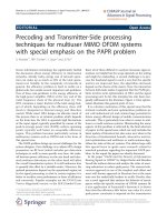
Fig 2.1. Spectrum of a single OFDM sub-carrier and OFDM symbol
Figure 2.1 shows the spectrum of a single OFDM sub-channel and the spectrum of an
OFDM symbol, which are characterized by the fact that spectrum of different sub-carriers
overlaps. As shown in the figure, at the centre frequency of each carrier, the amplitude of
all other carriers’ signals are zero. This is called the “orthogonality” between sub-carriers.
Although the spectrum of different sub-carriers is overlapping with each other, there is no
interference caused by other sub-carriers as long as the OFDM signal is transmitted and
received at the precise center frequency of each sub-carrier. The orthogonality between
11
sub-carriers allows them to be spaced as close as theoretically possible. This overcomes
the problem of large carrier spacing required in FDMA.
Each carrier in an OFDM signal has a very narrow bandwidth (i.e. 1 kHz), thus the
resulting symbol rate is low. As mentioned in the previous section, signal with low
symbol rate has a high tolerance to multipath delay spread, as the delay spread must be
very long to cause significant inter-symbol interference.
Compared to CDMA, OFDM is more resistant to frequency selective fading since its
parallel nature allows errors in sub-carriers to be corrected. OFDM performs much better
than CDMA in a multipath environment since it is better at overcoming Inter Symbol
Interference (ISI), which happens when reflected signals overlap with the transmitted
signal. However, OFDM is more sensitive to frequency offset, which results in Inter
Carrier Interference (ICI).
2.2
Multipath Frequency Selective Fading Channel
Before getting into the structure of OFDM systems, we would like to discuss the
performance of OFDM systems over a multipath frequency selective fading channel. In
an ideal radio channel, the received signal would consist of only a single direct path
signal, which would be a perfect reconstruction of the transmitted signal. However in a
real channel, the signal is modified during transmission in the channel. The received
signal consists of a combination of attenuated, reflected, refracted, and diffracted replicas
of the transmitted signal. On top of all this, the channel adds noise to the signal and can
cause a shift in the carrier frequency if the transmitter, or receiver is moving (Doppler
12
effect). In a radio link, the RF signal from the transmitter may be reflected from objects
such as hills, buildings, or vehicles. This gives rise to multiple transmission paths at the
receiver.
2.2.1 Advantage of OFDM Systems in Frequency Selective Fading Channel
In any radio transmission, the channel spectral response is not flat. It has dips or fades in
the response due to reflections causing cancellation of certain frequencies at the receiver.
Reflections of near-by objects (e.g. ground, buildings, trees, etc) can lead to multipath
signals which have comparable signal power as the direct signal. This can result in deep
nulls in the received signal power due to the strong interference signal.
For narrow bandwidth transmissions if the null in the frequency response occurs at the
transmission frequency then the entire signal can be lost. This can be partly overcome in
two ways. By transmitting a wide bandwidth signal or spread spectrum as CDMA system
do, any dips in the spectrum only result in a small loss of signal power, rather than a
complete loss. Another method is to split the total transmission bandwidth into many
narrow-bandwidth carriers. This is exactly what is done in OFDM systems. The original
signal is spread over a wide bandwidth, so most likely nulls in the spectrum only affect a
small number of carriers rather than the entire signal. The information carried by those
lost carriers can be recovered by using some error correction techniques such as Forward
Error Correction (FEC) [12].
13
2.2.2 Guard Interval in OFDM Systems
In order to overcome the effect of mulitpath fading channel, guard interval is necessary in
OFDM sytems. One of the most important properties of OFDM transmissions is its high
level of robustness against multipath delay spread [13][14]. This is a result of the long
symbol period used, which minimizes the inter-symbol interference. The level of
multipath robustness can be further increased by the addition of a guard period between
transmitted symbols. The guard period allows time for multipath signals from the
pervious symbol to die away before the information from the current symbol is gathered.
The most effective guard period to use is a cyclic extension of the symbol. Part of the end
of the symbol waveform is put at the start of the symbol as the guard period, this
effectively extends the length of the symbol, while maintaining the orthogonality of the
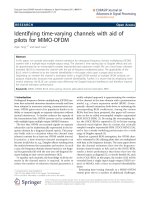
waveform. The cyclic extension of the symbol is called Cyclic Prefix (CP). Figure 2.2
shows the example of CP in OFDM systems.
cyclic prefix
Time
Fig 2.2. Cyclic prefix – a copy of the last part of OFDM symbol
CP enables cyclic convolution for each symbol, thus orthogonality is preserved even with
imperfect timing and channel impairment. In wireless environment, sub-carriers are still
14
orthogonal as long as the length of CP exceeds the time dispersion of wireless channels
(no ISI). This provides multipath immunity as well as symbol time synchronization
tolerance.
As long as the multipath delay echoes stay within the guard-period duration, there is
strictly no limitation regarding the signal level of the echoes: they may even exceed the
signal level of the shorter path! The signal from all paths is combined at the input of the
receiver and result in a stronger combined signal. Since the FFT is energy conservative,
the energy of the combined signal is the summation of all the signal energy from different
paths. On the other hand, the delay spread begins to cause inter-symbol interference
when it is longer than the guard interval. However, they do not cause significant
problems as long as the echoed signal is sufficiently weak. This is true most of the time
as multipath echoes delayed longer than the guard period will have been reflected of very
distant objects.
Other variations of guard periods are possible. One possible variation is to insert zeroamplitude signal into adjacednt OFDM systems. The OFDM symbols can be easily
identified by using this method. It also allows for symbol timing to be recovered from the
signal, simply by applying envelop detection. The disadvantage of using this guard period
method is that the zero period does not give any multipath tolerance. Throughout this
work, the CP based guard interval is adopted.
15
2.3
Generation of OFDM Systems
In this section, it is introduced that how data is modulated and demodulated in OFDM
systems. Details are given on how data is modulated and transmitted and then recovered
at the receiver in a digital approach of the OFDM scheme.
2.3.1 FFT and IFFT in OFDM Systems
In order to achieve a high spectral efficiency, the frequency response of the sub-channels
are overlapping and orthogonal to each other, which gives the name of OFDM. To
generate OFDM symbols successfully, the relationship between all the carriers must be
carefully controlled to maintain the orthogonality of the carriers. OFDM is generated by
firstly choosing the spectrum required, based on the input data, and modulation scheme
used. Each carrier to be produced is assigned some data to transmit. The required
amplitude and phase of the carrier is then calculated based on the modulation scheme
(typically differential BPSK, QPSK, or QAM). The required spectrum is then converted
back to its time domain signal using an Inverse Fourier Transform. In most applications,
an Inverse Fast Fourier Transform (IFFT) is used. The IFFT performs the transformation
very efficiently, and provides a simple way of ensuring the carrier signals produced are
orthogonal.
The FFT transforms a cyclic time domain signal into its equivalent frequency spectrum.
This is done by finding the equivalent waveform, generated by a sum of orthogonal
sinusoidal components. The amplitude and phase of the sinusoidal components represent
the frequency spectrum of the time domain signal. The IFFT performs the reverse process,
transforming a spectrum (amplitude and phase of each component) into a time domain
16
signal. An IFFT converts a number of complex data points, of length that is a power of 2,
into the time domain signal of the same number of points. Each data point in frequency
spectrum used for an FFT or IFFT is called a bin.
The orthogonal carriers required for the OFDM signal can be easily generated by setting
the amplitude and phase of each frequency bin, then performing the IFFT. Since each bin
of an IFFT corresponds to the amplitude and phase of a set of orthogonal sinusoids, the
reverse process guarantees that the carriers generated are orthogonal
2.3.2 Digital Approach of OFDM
A possible realization of an OFDM scheme can be dramatically simplified if a digital
approach is used. The approach is based on the use of FFT to generate and to demodulate
the transmitted signal. The flowing figure shows the digital implementation of OFDM
systems.
cos( 2 π f c t )
sk
S
Bit Stream
/
P
QAM
Encoder
xk
Nc-IFFT
Real
D/A
x
Re (U (t ) )
P
/
S
Im (U (t ) )
Imag
D/A
Transmitter
+
BPF
x
s(t)
− sin( 2π f c t )
n(t)
r(t)
cos( 2 π f c t )
S I (t )
x
LPF
Bit Stream P
/
S
QAM
Decoder
Nc-FFT
S
/
P
BPF
A/D
SQ (t )
x
LPF
Receiver
− sin( 2π f c t )
Figure 2.3 A digital approach of OFDM systems
17
Consider a sequence of N symbols, each symbol being represented by a point in a 2-D
constellation. These symbols can be written as:
sk = rk e jϕk = ak + jbk
(2.1)
where ak , bk are the coordinates of the point that represents the symbol k.
Then an inverse fast Fourier transform is computed on this set of symbols.
N −1
∑ sk exp( j 2π nk / N );
xk =
n = 0,1….N-1
(2.2)
k =0
The signal xk feeds a digital to analog converter to give the complex baseband signal
U (t ) .
U (t ) =
N −1
∑ xk exp( j 2π f k t )
k =0
(2.3)
where f k = k / T , 0 ≤ t ≤ T and T is the symbol duration
Then the signal is converted to radio frequency and transmitted through channel.
S (t ) = Re (U (t ) ) cos(2π f c t ) − Im (U (t ) ) sin(2π f c t )
N −1
=
∑
k =0
(2.4)
ak cos ( 2π ( f c + f k )t ) − bk sin ( 2π ( f c + f k )t )
where f c is the center frequency.
S (t ) is the transmitted signal during one modulation period, one complete OFDM symbol
S u (t ) in the time domain is described as
S u (t ) =
∞
∑S
j = −∞
j
(t − jT ) × Π (t − jT )
(2.5)
18
where Π (t ) = 1 .
0≤t
Π (t ) = 0
otherwise.
At the receiver, the signal is down-converted to an intermediate frequency (IF), and
quadrature demodulated.
S (t ) cos(2π f c t ) =
1 N −1
1
{ak cos(2π f k t ) − bk sin(2π f k t )} = S I (t )
∑
2 k =0
2
1 N −1
1
− S (t ) sin(2π f c t ) = ∑ {ak sin(2π f k t ) + bk cos(2π f k t )} = SQ (t )
2 k =0
2
(2.6)
Then the complex base-band signal U (t ) can be generated:
U (t ) = S I (t ) + jS Q (t ) = rk cos(2πf k t + ϕ k ) + jrk sin( 2πf k t + ϕ k )
N −1
= ∑ rk exp[ j (2πf k t + ϕ k )]
(2.7)
k =0
The demodulation process is based on the following orthogonality conditions:
T
∫0 rk cos(2π f k t + ϕk ) cos(2π f k t )dt = 0
,
=
T
T
rk cos(ϕ k ) = a k
2
2
if k= k ,
T
∫0 rk cos(2π f k t + ϕk ){− sin(2π f k t )}dt = 0
,
=
T
T
rk sin(ϕ k ) = bk
2
2
if k≠ k ,
(2.8)
if k≠ k ,
if k= k ,
(2.9)
As shown in equation (2.8) and (2.9), the transmiited signal, sk = ak + jbk , is finally
recovered at the receiver.
19
2.4
Generation of MIMO-OFDM Systems
Various schemes that employ multiple antennas at the transmitter and receiver are being
considered to improve the range and performance of communication systems. By far the
most promising multiple antenna technology today is called multiple-input multipleoutput (MIMO) system. MIMO systems employ multiple antennas at both the transmitter
and receiver.
MIMO-OFDM combines OFDM and MIMO techniques thereby achieving spectral
efficiency and increased throughput. A MIMO-OFDM system transmits independent
OFDM modulated data from multiple antennas simultaneously. At the receiver, after
OFDM demodulation, MIMO decoding on each of the subchannels extracts the data from
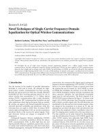
all the transmit antennas on all the subchannels. The block diagram of a MIMO-OFDM
systems is shown in Figure 2.4.
Modulator
Modulator
Data
h11
x1
h12
h1N
x2
r1
r2
Encoder
MIMO
Receiver
hM 1
hM 2
Modulator
xM
hMN
rN
Figure 2.4 Block diagram of MIMO-OFDM
Define the transmitted vector x = [ x1 , x2 ,...xM ] and the received vector r = [ r1 , r2 ,...rN ] .
T
T
Independent data x1 , x2 ,...xM are transmitted on different transmit antennas simultaneously
20
and in the same frequency band. Assuming N receive antennas and representing the
signal received by each antenna as ri , we have:
r1 = h11 x1 + h21 x2 + ... + hM 1 xM
r2 = h12 x1 + h22 x2 + ... + hM 2 xM
...
rN = h1N x1 + h2 N x2 + ... + hMN xM
(2.10)
As can be seen from the above set of equations, in making their way from the transmitter
to the receiver, the independent signals { x1 , x2 ,...xM } are all combined. Traditionally this
“combination” has been treated as interference. However, by treating the channel as a
matrix, we can in fact recover the independent transmitted streams { xi }. To recover the
transmitted data stream { xi } from the { ri }, we must estimate the individual channel
weights hij , construct the channel matrix H . Several approaches have been developed to
for channel estimation in OFDM systems [15][16]. Having estimated H , multiplication
of the vector r with the inverse of H produces the estimate of the transmitted vector x .
Because multiple data streams are transmitted in parallel from different antennas, there is
a linear increase in throughput with every pair of antennas added into the system [17]. An
important fact to note is that unlike traditional means of increasing throughput, MIMO
systems do not increase bandwidth in order to increase throughput. They simply exploit
the spatial dimension by increasing the number of unique spatial paths between the
transmitter and receiver.
As a result, without increasing bandwidth (a very expensive commodity) or total transmit
21
power, we can achieve substantial throughput improvement by using MIMO-OFDM.
This has significant ramifications as it suggests that operators can provide broadband
services within the current spectrum that they have purchased. Staying at the current
carrier frequencies implies that: (a) Signals can propagate further thus reducing the cost
of overall network deployment; (b) RF subsystems can be built using today’s well
understood and inexpensive processes.
22
Chapter 3 Carrier Frequency Offset
As mentioned, the OFDM systems are more sensitive to CFO than other communication
systems. In this chapter, the effect of CFO on Signal to Noise Ratio (SNR) and Bit Error
Rate (BER) of OFDM systems is analyzed in detail. Then, methods to estimate and
compensate the CFO available in the literature are introduced and compared.
3.1
Effect of CFO in OFDM Systems
It has been demonstrated that OFDM systems is much more sensitive to Carrier
Frequency Offset than other single carrier systems [18][19]. As introduced in the first
chapter, CFO can be normalized with respect to the subcarrier bandwidth and divided
into the integer part and fractional part for convenience. Integer CFO need to be corrected
perfectly since it causes a cyclic shift of subcarriers and a phase change proportional to
the OFDM symbol number. In this thesis, we assume that the integer part of CFO has
been estimated and compensated. Our study focuses on the effect of fractional CFO.
Fractional CFO attenuates the desired signal, adds phase, and causes an inter-carrier
interference (ICI). Fig 3.1 shows the relationship between CFO and ICI.
23
CFO
Figure 3.1 The relationship between CFO and ICI
Carrier frequency offset also reduces the signal to noise ratio (SNR) and hence increases
the bit error rate (BER). Unlike the integer CFO, the fractional CFO cannot be corrected
perfectly in practice. How fractional CFO affects the SNR and BER of OFDM systems is
discussed in the following section.
3.1.1 Effect of CFO on SNR for AWGN Channel
For an Additive White Gaussian Noise (AWGN) channel, all the elements of channel
impulse response in frequency domain are equal to one. Denote the channel impulse
response in frequency domain as H (k ) , H (k ) = 1 for all AWGN channels. In the absence
of carrier frequency offset, the received data frame in the frequency domain is
Y (k ) = X (k ) H (k ) + N (k )
= X (k ) + N (k )
k = 0,1,..., N c − 1
(3.1)
where, N c is the number of sub-carriers in one OFDM symbol.
As proved in [8], in the presence of a carrier frequency offset, the received data frame
after discarding the cyclic prefix and performing IFFT is
24
Y (k ) =
⎡ j π( N c − 1)ε ⎤
sin πε
X (k ) H (k ) exp ⎢
⎥ + ICI (k ) + N (k )
πε
N
c
⎣
⎦
N c sin
Nc
⎡ j π( N c − 1)ε ⎤
sin πε
=
X (k ) exp ⎢
⎥ + ICI (k ) + N (k )
πε
N
c
⎣
⎦
N c sin
Nc
(3.2)
Where, ε is the carrier frequency offset normalized by sub-carrier spacing. The total
occupied bandwidth in an OFDM system, fOFDM ≈
1
, where T is symbol duration. So,
T
the normalized carrier frequency offset ε is
ε=
Let C (ε) =
∆f
fOFDM / N c
≈ ∆fN cT
(3.3)
⎡ j π( N c − 1)ε ⎤
sin πε
exp ⎢
⎥ , equation (3.2) can be written as
πε
N
c
⎣
⎦
N c sin
Nc
Y (k )= C (ε) X (k ) + ICI (k ) + N (k )
ICI (k ) =
1
Nc
(3.4)
N c −1
⎡ j 2πi (k ' − k + ε) ⎤
'
X
(
k
)
exp
∑∑
⎢
⎥
Nc
i =0 k ' ≠ k
⎣
⎦
(3.5)
From equation (3.5), we can clearly see that the inter carrier interference is not zero
if ε ≠ 0 .
The desired signal power
2
2
E ⎡ C (ε) X (k ) ⎤ = C (ε) σ 2x
⎣
⎦
=
sin 2 πε
σ2x
2
2 πε
N c sin
Nc
(3.6)
2
It is clear that the signal power is attenuated, since C (ε) =
sin 2 πε
<1.
πε
N c 2 sin 2
Nc
25