A Study of Channel Estimation for OFDM Systems and System Capacity for MIMO-OFDM Systems
Bạn đang xem bản rút gọn của tài liệu. Xem và tải ngay bản đầy đủ của tài liệu tại đây (1.34 MB, 205 trang )
Abstract of thesis entitled
“A Study of Channel Estimation for OFDM Systems and
System Capacity for MIMO-OFDM Systems”
Submitted by
Zhou Wen
For the degree of Doctor of Philosophy
at the university of Hong Kong in July 2010
This thesis concerns about two issues for the next generation of wireless
communications, namely, the channel estimation for orthogonal frequency-division
multiplexing (OFDM) systems and the multiple-input multiple-output orthogonal
frequency-division multiplexing (MIMO-OFDM) system capacity.
For channel estimation for OFDM systems over quasi-static fading channels having
resolvable mulitipath number L, a novel fast linear minimum mean square error (LMMSE)
channel estimation method is proposed and investigated. The proposed algorithm deploys
Fourier transform (FFT) and the computational complexity is therefore significantly
reduced to O(Nplog2(Np)), as compared to that of O(Np3) for the conventional LMMSE
method, where the notation O(·) is the Bachmann–Landau function and Np is the number
of pilots for an OFDM symbol. The normalized mean square errors (NMSE) are derived in
closed-form expressions. Numerical results show that the NMSE is marginally the same
with that of the conventional LMMSE for signal to noise ratio (SNR) ranges from 0 dB to
25 dB. For channel estimation for OFDM systems over fast fading and dispersive channels,
a novel channel estimation and data detection method is proposed to reduce the
inter-carrier interference (ICI). A new pilot pattern composed of the comb-type and the
grouped pilot pattern is proposed. A closed-form expression for channel estimation mean
square error (MSE) has been derived. For SNR = 15 dB, normalized Doppler shift of 0.06,
and L = 6, both computer simulation and numerical results have consistently shown that
the ICI is reduced by 70.6% and 43.2%, respectively for channel estimation MSE and bit
error rate (BER). The pilot number per OFDM symbol is also reduced significantly by
92.3%, as compared to the comb-type pilot pattern.
A closed-form mathematic expression has been proposed for the capacity of the
closed-loop MIMO-OFDM systems with imperfect feedback channel. The lower threshold
of feedback SNR is derived. For L = 6, numerical results show that the lower threshold of
feedback SNR is proportional to antenna numbers N′ and system SNR. The increasing rate
of the feedback SNR threshold increases from 0.82 to 1.01 when N′ increases from 2 to 16.
The variance and mean of OFDM system capacity over Rayleigh channels and Ricean
channels have been respectively investigated that the closed-form expression for the
capacity variance has been proposed. The resultant system capacity variances over the two
channels are respectively evaluated by numerical method and also verified by computer
simulation. The joint probability density function (PDF) of two arbitrary correlated Ricean
random variables has also been derived in an integral form. Numerical results reveal that
the variance of OFDM system is proportional to SNR and inversely proportional to L for
the two channels respectively. For the same two respective channels, the variance
marginally increases with a linear rate of 0.166 bit2/dB and 0.125 bit2/dB, when L = 2 and
SNR ranges from 0 dB to 15 dB. The variance is reduced from 1.75 bit2 to 1.30 bit2 and
from 1.48 bit2 to 1.26 bit2, when SNR = 10 dB and L ranges from 2 to 4.
(Total words: 495)
A Study of Channel Estimation for OFDM Systems and
System Capacity for MIMO-OFDM Systems
by
Zhou Wen
B. Eng., M. Eng., USTC, P. R. China
A thesis submitted in partial fulfillment of the requirements for the Degree of
Doctor of Philosophy at the university of Hong Kong in July 2010.
Declaration
I declare that this thesis represents my own work, except where due
acknowledgement is made, and that it has not been previously included in a
thesis, dissertation or report submitted t to this University or any other
institution for a degree, diploma, or other qualifications.
Signature: ___________
Zhou Wen
i
Acknowledgements
I would like to take this opportunity to express my gratitude to all the people who have
ever helped me in the thesis writing and the course of the research.
My sincere and hearty thanks and appreciations go firstly to my supervisor, Dr. W.H. Lam,
whose suggestions and encouragement have given me much insight into the research work.
It has been a great privilege and joy to study under his guidance and supervision. His
insightful observation and effective feedback inspired me during the research. Furthermore,
it is my honor to benefit from his personality and diligence, which I will treasure my whole
life.
I also gratefully acknowledge Prof. V.O.K. Li, Prof. G.L. Li, Prof. Y.C. Wu, Prof. S.C.
Chan, Prof. T.S. Ng and Prof. Agnes S.L. Lam for their interesting courses and helpful
discussions. I would like to thank the office staff and technical staff from the EEE
department for their helpful administrative and facility supports. Especially, Ms. Julie
Hung’s readiness to help students is very impressive. I also appreciate the HKSAR
government for the studentship support to the study in the University of Hong Kong.
I am extremely grateful to all my friends and classmates who have kindly provided me
assistance and companionship in the process of preparing this thesis: Dr. Zhi Zhang, Dr.
Zhiqiang Chen, Dr. Mingxiang Xiao, Dr. Fei Mai, Mr. Xueyong Liu, Mr. Xiaoguang Dai,
Ms. Ziyun Shao, Mr. Ka-Chung Leung, Mr. Peng Zhang, Dr. Yanhui Geng, Ms. Qiong Sun,
Mr. Haoling Xiahou, Mr. Zhibo Ni, Mr. Jun Zhang, Mr. Xiaolei Sun, Mr. Chengwen Xing.
They have made the life during the past four years an enjoyable and memorable experience.
Finally, I wish to express my hearty gratitude to my parents, for their encouragements and
love in all my endeavors.
ii
Contents
Declarations......................................................................................................................... i
Acknowledgements............................................................................................................. ii
Contents.............................................................................................................................. iii
List of Figures.....................................................................................................................vii
Chapter 1: Introduction...................................................................................................... 1
1.1 Research motivation................................................................................................ 4
1.2 Organization and contributions of the thesis........................................................... 5
Chapter 2: OFDM systems and MIMO systems .............................................................. 9
2.1 Wireless Channel................................................................................................... 10
2.1.1 Large scale propagation ............................................................................. 11
2.1.2 Small scale propagation ............................................................................. 13
2.1.3 Typical wireless channel models................................................................ 17
2.2 OFDM systems ..................................................................................................... 20
2.2.1 Basic principles and characteristics for OFDM systems ........................... 21
2.2.2 Peak-to-Average (PAR) of OFDM systems ............................................... 30
2.2.3 Channel estimation for OFDM systems..................................................... 33
2.2.4 Synchronization of OFDM systems ........................................................... 38
2.2.5 Advantages and disadvantages of OFDM systems .................................... 39
2.3 MIMO systems...................................................................................................... 40
2.3.1 Basic MIMO system model ....................................................................... 40
2.3.2 Functions of MIMO systems...................................................................... 42
2.3.3 Overview of Space Time codes.................................................................. 45
2.3.4 Capacity of MIMO systems ....................................................................... 52
iii
2.4 MIMO-OFDM systems......................................................................................... 54
2.5 Summary ............................................................................................................... 56
Chapter 3: Channel estimation for OFDM systems over quasi-static fading channels
............................................................................................................................................. 57
3.1 Introduction........................................................................................................... 58
3.2 System Model ....................................................................................................... 61
3.3 The Proposed Fast LMMSE Algorithm ................................................................ 63
3.3.1 Properties of the channel correlation matrix in frequency domain ............ 63
3.3.2 The proposed fast LMMSE channel estimation algorithm ........................ 65
3.3.3 Computational complexity comparison between the proposed method and
the conventional LMMSE method ...................................................................... 69
3.4 Analysis of the Mean Square Error (MSE) of the Proposed Fast LMMSE
Algorithm .................................................................................................................... 70
3.4.1 MSE analysis of the conventional LMMSE algorithm.............................. 71
3.4.2 MSE analysis for the proposed fast LMMSE algorithm............................ 72
3.5 Numerical and Simulation Results........................................................................ 75
3.6 Conclusion ............................................................................................................ 81
Chapter 4: Channel estimation and data detection for OFDM systems over fast
fading channels.................................................................................................................. 87
4.1 Introduction........................................................................................................... 88
4.2 System Model ....................................................................................................... 91
4.3 The Proposed Channel Estimation and Data Detection ........................................ 92
4.3.1. The proposed pilot pattern ........................................................................ 92
iv
4.3.2. Channel Estimation and data detection for the first M1 OFDM symbols of
each block ........................................................................................................... 94
4.3.3. Channel estimation and data detection for the last M2 OFDM symbols of
each block ........................................................................................................... 95
4.3.4. Summary of the proposed channel estimation and data detection ............ 98
4.4. Analysis of MSE of the proposed channel estimation method ............................ 99
4.4.1. MSE analysis of channel estimation for the first M1 OFDM symbols ... 100
4.4.2. MSE analysis of channel estimation for the last M2 OFDM symbols .... 103
4.4.3 MSE analysis of channel estimation for one OFDM block ..................... 105
4.5 Numerical and Simulation Results...................................................................... 106
4.6. Conclusion ......................................................................................................... 112
Chapter 5: MIMO-OFDM system capacity with imperfect feedback channel ......... 118
5.1 The open-loop and closed-loop capacity for MIMO Systems ............................ 119
5.1.1 MIMO system model ............................................................................... 119
5.1.2 MIMO system capacity............................................................................ 120
5.1.3 Numerical Results and discussion............................................................ 124
5.2 The closed-loop capacity with imperfect feedback channel for MIMO-OFDM
systems ...................................................................................................................... 127
5.2.1 System Model .......................................................................................... 128
5.2.2 Closed-Loop Capacity and Feedback SNR for MIMO-OFDM Systems 130
5.2.3 Numerical Results .................................................................................... 136
5.3 Summary ............................................................................................................. 142
Chapter 6: Capacity of OFDM systems over time and frequency selective fading
v
channels............................................................................................................................ 144
6.1 Introduction......................................................................................................... 145
6.2 OFDM System Model......................................................................................... 147
6.3 OFDM System Capacity ..................................................................................... 148
6.3.1 OFDM system capacity over Rayleigh fading channels .......................... 148
6.3.2 OFDM system capacity over Ricean fading channels ............................. 153
6.4 Numerical and Simulation Results...................................................................... 157
6.5 Conclusion .......................................................................................................... 161
Chapter 7: Conclusions and future works .................................................................... 167
7.1 Conclusions......................................................................................................... 167
7.2 Future works ....................................................................................................... 169
APPENDIX A: The derivation of the rank of channel frequency autocorrelation matrix
RHH in Chapter 3............................................................................................................... 170
APPENDIX B: The derivation of equation (3-20) in Chapter 3....................................... 171
APPENDIX C: The derivation of the joint PDF of two arbitrary correlated Ricean random
variables ............................................................................................................................ 173
Appendix D: List of Abbreviations................................................................................... 176
REFERENCES.................................................................................................................. 179
Publications....................................................................................................................... 191
vi
List of Figures
Fig 1.1: Organization of the thesis. ....................................................................................... 6
Fig 2.1: Path Loss, shadowing and multipath versus distance............................................ 11
Fig 2.2: The Doppler power spectrum function expressed by (2-4). .................................. 14
Fig 2.3: The multi-path effect between the transmitter and the receiver in wireless
communication........................................................................................................ 14
Fig 2.4: Time varying impulse response of a wireless channel, for the path number N = 3, 4,
and 5........................................................................................................................ 15
Fig 2.5: Four kinds of small scale propagations. ................................................................ 16
Fig 2.6: PDFs for Rayleigh fading with the variance σ2 = 0.5, 2, and 5, respectively........ 17
Fig 2.7: PDFs for Ricean fading with Ricean factor Kr = 0 dB, 10 dB, and 20 dB,
respectively.............................................................................................................. 18
Fig 2.8: PDFs for Nagakami-m fading with m = 0.5, 1, and 10.......................................... 19
Fig 2.9: The continuous OFDM system model................................................................... 22
Fig 2.10: The waveform of Gk ( w) ....................................................................................... 24
Fig 2.11: Equivalent transmitter for OFDM systems.......................................................... 25
Fig 2.12: Equivalent receiver for OFDM systems. ............................................................. 25
Fig 2.13: CP for an OFDM symbol..................................................................................... 26
Fig 2.14: SNRloss versus CP length. .................................................................................. 27
Fig 2.15: The inter-symbol interference of OFDM systems without CP. ........................... 28
Fig 2.16: Extraction of the data in frequency domain......................................................... 28
Fig 2.17: The discrete baseband OFDM system model. ..................................................... 29
Fig 2.18: The output power versus the input power for a power amplifier......................... 31
Fig 2.19: The power spectrum comparison between the input signal and the output signal
passing through an amplifier. .................................................................................. 32
Fig 2.20: Two kinds of pilot patterns (black dot: pilot, white dot: user data). .................... 34
Fig 2.21: Pilot-aided channel estimation for OFDM systems............................................. 35
Fig 2.22: The basic MIMO system model. ......................................................................... 40
Fig 2.23: Received signal after diversity operation. ........................................................... 43
vii
Fig 2.24: Diversity-multiplexing tradeoff, d*(r) versus r. .................................................. 44
Fig 2.25: The Alamouti STBC diagram for 2×2 MIMO systems. ...................................... 46
Fig 2.26: V-BLAST system diagram................................................................................... 49
Fig 2.27: The baseband MIMO-OFDM system model....................................................... 55
Fig 3.1: Baseband OFDM system. ...................................................................................... 61
Fig 3.2: Channel estimation based on comb-type pilots. .................................................... 62
Fig 3.3: The first row of the channel autocorrelation matrix R Hp Hp , A . ............................. 82
−1
β ⎞
⎛
Fig 3.4: The first row of the LMMSE matrix R Hp Hp ⎜ R Hp Hp +
I ⎟ with different SNRs.
SNR ⎠
⎝
................................................................................................................................. 83
Fig 3.5: Normalized Mean square error (NMSE) of channel estimation of LMMSE
algorithm versus that of the proposed fast LMMSE algorithm by computer
simulation and numerical method. .......................................................................... 83
Fig 3.6: NMSE of LMMSE algorithm with matched SNR and mismatched SNRs versus
SNR, by simulation and numerical method, respectively. ...................................... 84
Fig 3.7: NMSE of the proposed fast LMMSE algorithm with matched SNR and
mismatched SNRs versus SNR, by simulation and numerical method, respectively.
................................................................................................................................. 84
Fig 3.8: Bit error rate (BER) of the LS, LMMSE, the proposed fast LMMSE and perfect
channel estimation versus SNR............................................................................... 85
Fig 3.9: BER comparison between LMMSE channel estimation with matched SNR and
LMMSE channel estimation with designed SNRs.................................................. 85
Fig 3.10: BER comparison between the proposed fast LMMSE channel estimation with
estimated SNR and the proposed fast LMMSE channel estimation with designed
SNRs. ...................................................................................................................... 86
Fig 4.1: Pilot pattern (gray circle: user data, black circle: pilot). ..................................... 114
Fig 4.2: The normalized mean square error (NMSE) of channel estimation for the first M1
OFDM symbols, for f d T = 0.01, 0.06 and 0.1, respectively. ................................. 114
Fig 4.3: The NMSE of channel estimation based on equi-spaced and grouped pilot pattern,
viii
for the polynomial order Q =1, 2, 3 and the normalized Doppler shift f d T = 0.01 and
0.1, respectively..................................................................................................... 115
Fig 4.4: The NMSE of channel estimation based on grouped pilot pattern, for c =1, 2, 3 and
the normalized Doppler shift f d T = 0.01 and 0.1, respectively.............................. 115
Fig 4.5: The NMSE of channel estimation based on grouped pilot pattern, for the number
of pilot groups N group =18, 36, 72 and the normalized Doppler shift f d T = 0.01 and
0.1, respectively..................................................................................................... 116
Fig 4.6: The NMSE of channel estimation for the proposed algorithm and LS algorithm by
numerical method and simulation at f d T = 0.01 and 0.06, respectively. ............... 116
Fig 4.7: Bit error ratio (BER) of LS, the proposed algorithm and the algorithm in [29], for
normalized Doppler shift f d T = 0.01 and 0.06, respectively. ................................ 117
Fig 5.1: The eigenmode transmission of MIMO systems. ................................................ 123
Fig 5.2: The MIMO system open-loop capacity versus the number of transmitter
antennas NT , for the number of receiver antennas N R = 1 ...................................... 124
Fig 5.3: The MIMO system open-loop capacity versus the number of receiver antennas N R ,
for the number of transmitter antennas NT = 1 ....................................................... 124
Fig 5.4: The capacities of the N by 1 MISO system, the 1 by N SIMO system, and the N by
N MIMO system as a function of N, for SNR = 5 dB........................................... 125
Fig 5.5: The open-loop and closed-loop capacity for MIMO systems, versus SNR. ....... 126
Fig 5.6: The closed-loop MIMO-OFDM system model. .................................................. 128
Fig 5.7: The open-loop and closed-loop system capacity for MIMO-OFDM systems
having different transmitter antenna and receiver antenna numbers. ................... 138
Fig 5.8: The capacity gain of the closed-loop capacity with imperfect feedback over that of
the open-loop capacity versus feedback channel SNR, for NT = N R = 4 . .............. 140
Fig 5.9: The capacity gain of closed-loop capacity with imperfect feedback over that of the
open-loop capacity versus feedback channel SNR, for system SNR = 10 dB...... 140
Fig 5.10: The lower threshold of the feedback SNR versus the MIMO-OFDM system SNR,
ix
for different antenna pairs. .................................................................................... 142
Fig 6.1: The PDF of the capacity at a certain subcarrier, fCi ,k ( x) in (6-36), for SNR = 0 dB,
5 dB, 10 dB, and 20 dB, respectively.................................................................... 162
Fig 6.2: The joint PDF of of | H (i, k1 ) |2 and | H (i, k2 ) |2 , f|H (i ,k )|2 ,|H (i ,k
1
2
2 )|
( x, y ) ,for the coefficient
of equation (6-23), γ = 0.61................................................................................... 162
Fig 6.3: The coefficient of equation (6-24), γ, versus different subcarrier gap between
k1 and k2 . ................................................................................................................ 163
Fig 6.4: The variance of OFDM system capacity for the number of channel paths L = 2, 4,
and 8, over the Rayleigh fading channel............................................................... 163
Fig 6.5 The variance of OFDM system capacity versus the CP of an OFDM symbol in unit
of sample point, over the Rayleigh fading channel............................................... 164
Fig 6.6: The variance of OFDM system capacity versus the number of subcarriers of one
OFDM symbol, for Rayleigh fading channels. ..................................................... 164
Fig 6.7: The variance of OFDM system capacity over Ricean fading channels for L = 2, 4,
8, respectively........................................................................................................ 165
Fig 6.8: The mean value of OFDM system capacity for Rayleigh fading channel and
Ricean fading channel, by numerical method. ...................................................... 165
Fig 6.9: The variance of OFDM system capacity for Rayleigh fading channel and Ricean
fading channel, by computer simulation and numerical method. ......................... 166
x
Chapter 1: Introduction
The research on wireless communication systems with high data rate, high spectrum
efficiency and reliable performance is a hot spot. There are several advanced
communication technologies or protocols proposed recently, including Orthogonal
frequency division multiplexing (OFDM) [1], multiple input multiple output (MIMO) [2],
Ultra-Wideband (UWB) technology [3], cognitive radio [4], World Interoperability for
Microwave Access (WiMAX) [92], and 3GPP Long Term Evolution (LTE) [92], [93].
OFDM is an efficient high data rate transmission technique for wireless communication.
OFDM presents advantages of high spectrum efficiency, simple and efficient
implementation by using the fast Fourier Transform (FFT) and the inverse Fast Fourier
Transform (IFFT), mitigration of inter-symbol interference (ISI) by inserting cyclic prefix
(CP) and robustness to frequency selective fading channel. MIMO is the use of multiple
antennas at both the transmitter and receiver to improve communication performance. It is
one of several forms of smart antenna technology. MIMO technology has attracted
attention in wireless communications, because it increases in data throughput without
additional bandwidth or transmit power. It achieves this by higher spectral efficiency and
link reliability or diversity. The combination of MIMO with OFDM technique is a
promising technique for the next generation wireless communication. A new protocol draft
employing the MIMO-OFDM as the physical layer technology, IEEE 802.11n, as an
amendment to IEEE 802.11 standards has been proposed [53]. Wireless LAN technology
1
has seen rapid advancements and MIMO-OFDM has gradually been adopted in its
standards. The following table shows the existing IEEE 802.11 WLAN protocols.
Table 1.1 Existing 802.11 WLAN Standards
IEEE Protocol Name
Standard Approved
Available Bandwidth
Frequency Band of
Operation
Non-Overlapping
Channels (US)
Data Rate per Channel
Modulation Type
802.11b
802.11a
802.11g
802.11n
Released in
2009
83.5/580
83.5 MHz 580 MHz 83.5 MHz
MHz
Sept. 1999 Sept. 1999
June
2003
2.4 GHz
5 GHz
2.4 GHz
2.4/5 GHz
3
24
3
3/24
1–11 Mbps 6–54 Mbps 1–54 Mbps
DSSS,
CCK
OFDM
DSSS,
CCK,
OFDM
1–600
Mbps
DSSS,
CCK,
OFDM,
MIMO
UWB is a technology for transmitting data spread over a large bandwidth (usually larger
than 500 MHz) that shares among users. UWB was traditionally applied in
non-cooperative radar imaging. Most recent applications include sensor data collection,
precision locating, and tracking applications. The concept of cognitive radio was first
proposed by Dr. J. Mitola and Prof. G. Q. Maguire [4] in 1999 and was an extension to the
concept of software radio. Cognitive radio is an intelligent communication system that
could detect and track the communication environments. It would adjust the transmitter
and the receiver’s parameters adaptively according to the changes
of environment
parameters such as the mobile velocity of the user, so that the system stability could be
2
ensured, the system performance could remain a good condition, and the spectrum
efficiency could be improved. WiMAX is a telecommunications protocol that provides
fully mobile Internet access. The name "WiMAX" was created by the WiMAX Forum,
which was founded in 2001. The forum refers to WiMAX as a standards-based technology
enabling the delivery of last mile wireless broadband access as an alternative to cable and
digital subscriber line (DSL). The basis of WiMAX is IEEE 802.16 standard which is
sometimes referred to as “WiMAX” equivalently. The current WiMAX revision is based
on IEEE 802.16e, which was approved in December 2005. The physical layer of WiMAX
adopts a lot of advanced technologies such as scalable orthogonal frequency division
multiplexing access (OFDMA), MIMO, adaptive antenna array and so on. Current
WiMAX that is based on the IEEE 802.16e protocol belongs to 3G family. Future WiMAX
is based on IEEE 802.16m, which has been submitted to the International
Telecommunication Union (ITU) for International Mobile Telecommunication Advanced
(IMT-Advanced) standardization. Future WiMAX, or the proposed WiMAX release 2, is
considered as a candidate of 4G family. LTE is the latest standard in the mobile
communication systems. The current generation of mobile communication system is
collectively known as 3G. Although LTE is often referred to as 4G, the first released LTE is
actually a 3.9G technology as it does not completely meet the 4G requirements. The main
advantages of LTE include high throughput, low latency, plug and play, a simple
architecture resulting in low power consumption, supporting seamless passing by base
stations with former wireless networks such as Global System for Mobile Communications
3
(GSM), Universal Mobile Telecommunications System (UMTS), and CDMA2000. LTE
also adopts OFDM and MIMO technologies in the physical layer. It uses a 2 by 2 MIMO
system as the basic configuration, that is, both the base station and the mobile end equip 2
antennas. The next step for LTE evolution is LTE Advanced and is currently being
standardized by 3rd Generation Partnership Project (3GPP) organization.
The thesis studies two issues: channel estimation for OFDM systems and
MIMO-OFDM system capacity. The chapter is organized as follows. Section 1.1 describes
the research motivation. Section 1.2 provides the thesis contributions and the overall
organization of the thesis.
1.1 Research motivation
Earlier OFDM systems such as the digital audio broadcasting (DAB) system in Europe
does not require channel estimation module. It only uses DPSK demodulation for the sake
of reducing the complexity of the receiver. However, with increasing demands of high data
transmission rate and reliable communication quality, channel estimation has become a
necessary part in the OFDM system. For example, the digital video broadcasting (DVB)
system adopts the channel estimation module. In a broadband wireless environment, the
channel is often time varying and frequency selective, which distorts the transmitted signal
significantly, so that accurate and real time channel estimation is the challenging topic in
the OFDM system. Channel state information can be used for the detection of the received
signal, improving the capacity of the system throughput by adjusting the modulation at the
4
transmitter through the feedback. Therefore, one issue of the thesis studies channel
estimation for OFDM systems over time varying and frequency dispersive fading
channels.
With the increasing number of mobile phone users and higher demands for wireless
services, future communication systems should have higher system capacity. MIMO
technique is a breakthrough of improving system capacity. Telatar [46] and Foschini [47]
have firstly formulated the system capacity of the MIMO systems assuming independent
and identically distributed fading at different antennas. They have proved that the MIMO
system capacity for n transmitter antennas and n receiver antennas increases linearly with
n at a fixed transmitter power. That is, MIMO systems can improve the system capacity
significantly without increasing the system bandwidth. A number of MIMO techniques
known as layered space time architectures or Bell Laboratories layered space time
(BLAST) architectures [5]–[8] have been proposed. Many studies on MIMO system
capacity have been conducted. Since the combination of MIMO with OFDM is a trend, a
lot of research work has been done on the MIMO-OFDM system capacity. However, the
research on MIMO-OFDM system capacity with imperfect feedback channel is not mature
and corresponding work is not much. Therefore, the second issue of the thesis is to study
the MIMO-OFDM system capacity with imperfect feedback channels.
1.2 Organization and contributions of the thesis
Firstly, we briefly describe the organization of the thesis. Chapter 1 gives a general
5
introduction, research motivation, organization, and contributions of the thesis. Chapter 2
describes the basic OFDM system model and MIMO system model. The wireless channel
model, the principles of OFDM and MIMO systems, the combination of MIMO and
OFDM, that is, MIMO-OFDM system is also introduced in Chapter 2. Next, as depicted in
Fig 1.1, the thesis begins with the first issue, that is, channel estimation. The proposed
channel estimation method in Chapter 3 is based on quasi-static fading channels and that in
Chapter 4 is based on fast fading channels. Then, the thesis switches to next issue, that is
system capacity. In Chapter 5, the MIMO-OFDM system capacity with imperfect feedback
channel is investigated. In Chapter 6, the capacity variances for OFDM systems over
Rayleigh and Ricean fading channels are derived, respectively. Finally, Chapter 7
concludes the thesis and discusses future research works.
Fig 1.1: Organization of the thesis.
6
Secondly, the major contributions of this thesis are summarized as follows.
A fast linear minimum mean square error (LMMSE) channel estimation method for
OFDM systems over slow fading channels has been proposed. Unlike the
conventional method, the channel state information is not needed in advance.
Almost the same performance with the conventional LMMSE channel estimation in
terms of the normalized mean square error (NMSE) of channel estimation and bit
error rate (BER) could be achieved for the proposed method. The computational
complexity can be reduced significantly since the proposed method replaces the
inverse operation with FFT operation. (Chapter 3)
A new pilot pattern and corresponding channel estimation method and data
detection for OFDM systems over fast fading channels have been proposed. The
proposed channel estimation and data detection based on the proposed pilot pattern
can eliminate inter-carrier interference (ICI) effect effectively. And the number of
required pilots is also reduced significantly, compared with the conventional least
square (LS) method. MSE analysis for the channel estimation based on the grouped
pilot pattern is provided, too. (Chapter 4)
The closed-loop MIMO-OFDM system capacity with imperfect feedback channel
has been formulated. We use the feedback SNR to measure the closed-loop capacity.
Since low feedback SNR may not yield positive gain of closed-loop capacity over
7
open-loop capacity, there exists a lower threshold of feedback SNR. The lower
thresholds for different antenna pairs are further investigated by numerical method.
(Chapter 5)
The variances of OFDM system capacity over Rayleigh fading channels and Ricean
fading channels have been derived. The effects of SNR, the number of channel
paths, power profile of fading channel, the delay of the channel on the variance
have been thoroughly investigated, for both multipath Rayleigh channels and
multipath Ricean channels. The joint PDF of two arbitrary correlated Ricean
random variables has been provided in an integral form. (Chapter 6)
8
Chapter 2: OFDM systems and MIMO systems
Since the thesis studies the channel estimation for OFDM systems and system capacity for
MIMO-OFDM systems, this chapter briefly introduces the background of OFDM systems
and MIMO systems.
OFDM is an effective technology which provides high spectrum efficiency, high data
transmission rate and is robust to multi-path fading [1]. OFDM has already been widely
put into practice in DAB system, DVB system and WLAN. MIMO systems which employ
multi-element antenna arrays at the transmitter and receiver ends are capable of high data
rate transmission. A number of MIMO techniques known as layered space time
architectures or BLAST architectures have been proposed [5]-[7], [9].
As OFDM technique can mitigate the ISI and transform the frequency selective fading
channel into a set of flat fading channels, the combination of MMO with OFDM technique
is a trend for future wireless communication. A new protocol draft, IEEE 802.11n, as an
amendment to IEEE 802.11 standards has been proposed and investigated [53]. The draft
proposes MIMO-OFDM as the physical layer technique and is to be approved by IEEE.
The chapter is organized as follows. Section 2.1 provides an introduction to wireless
channel in communication systems. Section 2.2 describes the basic OFDM system model,
principles, and related key technologies in OFDM systems. Section 2.3 introduces the
basic MIMO system model and briefly overviews the existing MIMO systems. Section 2.4
presents the MIMO-OFDM system model. The last section 2.5 summarizes the chapter.
9
2.1 Wireless Channel
Since there exist reflections, scattering, and diffraction in the transmission of
electromagnetic wave, the spatial environments such as the landscape of a city,
obstructions and so on will make complicated impacts on the transmission of
electromagnetic wave. There are two kinds of propagation, including the large-scale
propagation and the small scale propagation. The signal variations due to path loss or
shadowing occur over relatively large distances, this variation is referred to as the large
scale propagation effects. Path loss is a major component in the analysis and design of the
link budget of a telecommunication system. The small scale propagation refers to the
phenomena that the amplitude of the received wireless signal varies very fast in a short
time period or a short distance. The sources of small scale propagation include the Doppler
shift effect and multi-path effect. We begin with the introduction of the large scale
propagation.
10
2.1.1 Large scale propagation
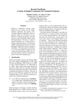
Fig 2.1: Path Loss, shadowing and multipath versus distance.
Fig 2.1 plots the ratio of the received-to-transmit power in dB versus the distance for
the combined effects of path loss, shadowing, and multipath. Observe that the free space
path loss is linearly proportional to the log-distance between the transmitter and receiver.
The shadowing loss has slower variations compared to that of the multipath effect. The
large scale path loss model has many successful types including the free space path loss
model, the Hata model, and the Okumura model and so on. Most of them are obtained by
a combination of the analytical and empirical methods. We next briefly introduce the free
space path loss model as an example of path loss effect.
Free space path loss model: An example of path loss effect
Consider a signal transmitted through free space to a receiver located at distance d from
the transmitter. It is assumed that there does not exist any obstructions between the
11