DSP algorithm and system design for UWB communication systems
Bạn đang xem bản rút gọn của tài liệu. Xem và tải ngay bản đầy đủ của tài liệu tại đây (515.07 KB, 86 trang )
DSP ALGORITHM AND SYSTEM DESIGN FOR
UWB COMMUNICATION SYSTEMS
YANG LIU
(B.Eng.(Hons.), NTU)
A THESIS SUBMITTED
FOR THE DEGREE OF MASTER OF ENGINEERING
DEPARTMENT OF ELECTRICAL & COMPUTER ENGINEERING
NATIONAL UNIVERSITY OF SINGAPORE
2006
ACKNOWLEDGEMENT
I would like to express my utmost appreciation to my supervisors, Dr. Zheng Yuanjin and
Prof. Hari Krishna Garg, for being so understanding, helpful and encouraging at all times
through my research and study in National University of Singapore and Institute of
Microelectronics. I am especially grateful for the invaluable guidance and constructive
suggestions offered by Dr. Zheng throughout the development of this dissertation.
I would also like to thank my friends, Mr. Cao Mingzheng, Miss Yan Jiangnan, Mr. Cao
Rui, Mr. Tong Yan, Miss Zhou Qiaoer, Miss Wei Xiaoqian and Miss Lu Miaomiao, for
their kindness and supportive work.
Many thanks to my family, for always being there for me, whenever and wherever.
Lastly I also wish to extend my appreciation to all the others who have, in one way or
another, helped in making this dissertation a very rewarding one.
It has been a pleasure working together.
I
TABLE OF CONTENTS
ACKNOWLEDGEMENT ..........................................................I
TABLE OF CONTENTS ..........................................................II
SUMMARY......................................................................... IV
LIST OF FIGURES ................................................................ V
LIST OF ABBREVIATIONS .................................................. VI
LIST OF ABBREVIATIONS .................................................. VI
LIST OF SYMBOLS ............................................................. IX
1 INTRODUCTION .............................................................. 1
1.1
Background ......................................................................................................... 2
1.2
Scope of the Thesis ............................................................................................. 9
1.3
Organization of the Thesis ................................................................................ 10
2 LITERATURE REVIEW .................................................. 11
2.1
IR & MB-OFDM .............................................................................................. 12
2.2
Rake Receiver ................................................................................................... 20
3 SYSTEM MODEL & RECEIVER DESIGN ......................... 24
3.1
Pulse-shaping & Modulation ............................................................................ 25
3.2
Multipath Channel Model ................................................................................. 27
II
3.3
BRake Receiver Structure................................................................................. 30
4 PERFORMANCE ANALYSIS ........................................... 33
4.1
Correlation Receivers ....................................................................................... 34
4.2
MMSE Criterion & Wiener Solution ................................................................ 39
4.3
LMS Analysis ................................................................................................... 46
4.4
BER Expression ................................................................................................ 50
4.5
Misadjustment................................................................................................... 54
5 SIMULATION RESULTS ................................................. 55
5.1
Theoretical versus Simulated BER ................................................................... 56
5.2
Effect of
5.3
BER Comparison with Other Rake Structures.................................................. 61
µ
on BER Approximation ............................................................... 59
6 CONCLUSION ............................................................... 64
6.1
Conclusion Remarks ......................................................................................... 64
6.2
Future Works..................................................................................................... 66
REFERENCES ..................................................................... 67
LIST OF PUBLICATIONS ..................................................... 72
III
SUMMARY
Ultra-Wideband (UWB) communication is recognized as one of the most promising
technologies for next generation Wireless Personal Area Network (WPAN) since it has the
potential to provide a low complexity, low cost, low power consumption, and high data
rate connectivity in communication systems. It relies on transmission of ultra-short (in
nanosecond scale) pulses and avoids using sinusoidal carriers or intermediate frequency
(IF) processing. One of the most significant features of UWB communication is its fine
multipath resolvability. To maximally exploit the channel diversity, a Rake receiver is
usually employed to effectively capture the multipath energy. Conventional Rake receivers
require channel information, including the multipath delay and attenuation, to be provided
before combing the multipath energy. However the channel information is unknown to the
receiver and difficult to estimate in practical UWB transmission systems.
In this thesis, a novel blind Rake (BRake) structure is proposed for high data rate low
power consumption UWB communication systems. The word “blind” here does not imply
that training sequence can be totally eliminated, but refers to the fact that the channel
information is not needed for the Rake system to perform effectively. In other words, it
avoids the estimation of multipath channel which must be provided for conventional Rake
receiver systems. The transceiver complexity is further reduced by using Analog-toDigital Converter (ADC) working at sub-Nyquist sampling rate. The closed form bit error
rate (BER) performance analysis is provided as well. Extensive simulations have been
carried out which verified the theoretical analysis.
IV
LIST OF FIGURES
Figure 1.1 Frequency & energy comparison for communication systems. ........................ 3
Figure 1.2 FCC regulated spectral mask for UWB indoor communication systems.......... 4
Figure 1.3 Operation distance and data rate of major wireless standards........................... 5
Figure 1.4 Comparison of UWB and conventional NB transceiver architectures.............. 6
Figure 2.1 The MB-OFDM frequency band plan. ............................................................ 13
Figure 2.2 A typical transceiver architecture for a MB-OFDM system............................ 14
Figure 2.3 Waveforms for derivatives of Gaussian monocycle. ....................................... 17
Figure 2.4 IR-UWB modulations...................................................................................... 19
Figure 2.5 A general Rake receiver structure.................................................................... 21
Figure 3.1 Typical CIRs for UWB indoor channels. ........................................................ 29
Figure 3.2 BRake receiver architecture. ........................................................................... 30
Figure 5.1 Tap weight. ...................................................................................................... 57
Figure 5.2 Tap weight difference and its histogram.......................................................... 57
Figure 5.3 Theoretical versus simulated BER for CM1-CM4.......................................... 58
Figure 5.4 Effect of µ on BER approximation................................................................. 60
Figure 5.5 BER performance for CM1. ............................................................................ 61
Figure 5.6 BER performance for CM2. ............................................................................ 62
Figure 5.7 BER performance for CM3. ............................................................................ 62
Figure 5.8 BER performance for CM4. ............................................................................ 63
V
LIST OF ABBREVIATIONS
A-STAR
ADC
ARake
ASIC
AWGN
BER
Agency of Science, Technology and Research
Analog-to-Digital Converter
All Rake
Application-Specific Integrated Circuit
Additive White Gaussian Noise
Bit Error Rate
BPSK
Binary Phase Shift Keying
BRake
Blind Rake
CFJ
Carrier Frequency Jitter
CFO
Carrier Frequency Offset
CIR
Channel Impulse Response
CM
Channel Model
CSI
Channel State Information
DC
Direct Current
DS
Direct Sequence
EIRP
Effective Isotropic Radiated Power
EM
Electromagnetic
FAS
Federal Aviation System
FCC
Federal Communication Commission
FPGA
FTT
Field Programmable Gate Array
Fast Fourier Transform
VI
GPS
IF
Global Positioning System
Intermediate Frequency
IFTT
Inverse Fast Fourier Transform
IME
Institute of Microelectronics
IR
Impulse Radio
ISI
Inter Symbol Interference
LMS
Least Mean Square
LPD
Low Probability of Detection
LPI
Low Probability of Interception
MA
Multi-user Access
MB-OFDM
Multi-Band Orthogonal Frequency Division Multiplexing
MB-UWB
Multi-Band Ultra-Wideband
MBOA
Multi-Band OFDM Alliance
MF
Matched Filter
MFEP
Matched Front-End Processor
MMSE
Minimum Mean Square Error
MRC
Maximum Ratio Combing
MSE
Mean Square Error
NB
OFDM
Narrowband
Orthogonal Frequency Division Multiplexing
PAM
Pulse Amplitude Modulation
PDP
Power Delay Profile
PPM
Pulse Position Modulation
PRake
Partial Rake
VII
PRT
Pulse Repetition Time
PSD
Power Spectral Density
R&O
RF
Report & Order
Radio Frequency
RMS
Root Mean Square
S-V
Saleh-Valenzuela
SNR
SRake
Signal to Noise Ratio
Selective Rake
TDL
Tapped Delay Line
TFC
Time Frequency Code
TFK
Time Frequency Kernel
U-NII
Unlicensed National Information Infrastructure
UWB
Ultra-Wideband
WLAN
Wireless Local Area Network
WPAN
Wireless Personal Area Network
VIII
LIST OF SYMBOLS
A
A factor to normalize the pulse energy
C
Channel Capacity
J
MMSE cost function
K
Total tap number in a branch
L
Total branch number
M
Total number of multipath in a channel
Μ
Misadjustment
X
Channel log-normal shadowing coefficient
m
The m th multipath component in a channel
W
Channel Bandwidth
g (t )
2nd order Gaussian derivative waveform
gm
Gaussian pulse vector based on real channel timing
g l ,k
Gaussian pulse vector based on receiver sampling timing
h(t )
Channel impulse response
r (t )
Received signal
rn (t )
s (t )
sI
w(t )
Received signal for n th symbol
Transmitted signal
Vector of signal after correlation
Noise signal
IX
wl ,k
Noise for k th tap of l th branch after correlation operation
wI
Vector of noise mixed with signal after correlation
w LK −I
Vector of pure noise after correlation
p n (t )
n th order Gaussian derivative waveform in time domain
Pn ( f )
n th order Gaussian derivative waveform in frequency domain
bn
Constellation for PAM/Transmitted symbol
bˆn
Estimated symbol
bn
Vector of training sequence
c nTH
User-specific TH code for n th impulse
cl , k
Weight for k th tap of l th branch
c nl ,k
Weight for k th tap of l th branch for symbol n during training phase
c
Tap weight vector
co
Optimum tap weight vector
cio
i th optimum tap weight
ciLMS
i th LMS tap weight
dn
Constellation for PPM
en
Error signal for n th symbol duration training phase
eiLMS
i th LMS error
vl , k
Input of the k th tap in the l th branch
v nl ,k
Input of the k th tap in the l th branch for symbol n
X
v
Tap input vector
yn
Decision signal for n th symbol
Eb
Bit energy
Ep
Pulse energy
I P× P
P × P identity matrix
L
Number of fingers in a Rake
Lb
Number of fingers in a SRake
Lp
Number of fingers in a PRake
Nc
Number of chips in each frame
Nf
Number of replicas in each transmitted symbol
N0
One side power spectrum density of AWGN
Pb
Bit error rate (BER)
Q
Eigenvector matrix
R
Tap input autocorrelation matrix
R g (⋅)
Pulse correlation function
S h~ (τ )
Delay spectrum
Tc
Chip duration
Td
Maximum excess delay of the channel
Tp
Impulse duration
T pr
Pulse repetition time
Ts
Symbol duration
XI
Tl
Channel time delay of the l th cluster
σ
Standard deviation of a Gaussian random variable
σ e2i
σ w2l ,k
Variance of LMS error
Variance of noise after correlation
γ
SNR ratio
φ
Processing gain
µ
Adaptation step size during training phase
∆
Pulse position offset in PPM
αm
Channel attenuation of the m th multipath component
α k ,l
Channel attenuation of the k th multipath in the l th cluster
αm
Vector of channel attenuation
τm
Channel delay of the m th multipath component
τ k ,l
Channel delay of the k th multipath in the l th cluster
τl
Receiver sampling interval of l th branch
τ l ,k
Receiver sampling time of the k th tap in the l th branch
τm
Vector of Channel delay
τ lk
Vector of receiver sampling time
τ RMS
∆τ
Λ
ΛS
Channel RMS delay spread
Delay between consecutive BRake branch
Cluster arrival rate of channel multipath
Diagonal eigenvalue matrix
XII
ςi
i th Eigenvalue
λ
Ray arrival rate of channel multipath in a cluster
λi
i th eigenvalue of autocorrelation matrix of input data
η
Successfully collected channel energy
E []
⋅
Expectation operation
δ (⋅)
Dirac delta function
Q(⋅)
Complementary cumulative distribution function
tr (⋅)
Matrix trace operation
⊗
Convolution operation
XIII
CHAPTER 1: INTRODUCTION
1 INTRODUCTION
This chapter gives a brief introduction of UWB communication systems. UWB
technology has been in used for more than a century. However it attracts real attention
both in industry and academy only after the Federal Communication Commission (FCC)
released a huge “new bandwidth” of 3.1-10.6 GHz for it in 2002. UWB applications
include, but not limit to, Wireless Personal Area Networks (WPANs), sensor networks,
imaging systems, vehicular radar systems, etc.
The scope and organization of the whole thesis are also presented in this chapter.
1
CHAPTER 1: INTRODUCTION
1.1 Background
Scientists and engineers have known about UWB signals since Guglielmo Marconi
invented radio communications utilizing enormous bandwidth as information was
conveyed by spark-gap devices more than a century ago. However the signals were more
difficult to control or detect than narrowband (NB, single-frequency) signals at that time.
Modern UWB technology came into the picture since 1960s, when the introduction of
UWB impulse radar systems was motivated by the high sensitivity to scatters and low
power consumption applications [1]-[3]. Commercially, the early UWB investigation was
largely under the aegis of the U. S. Department of Defense that adopted wideband signals
primarily for very accurate localization and imaging in the context of secure
communications [4], [5]. Academically, the UWB research and development were largely
pioneered by Prof. Scholtz and his group [6]-[9], [13], [28], [29], [32], focusing mainly on
low-rate applications.
UWB, as the name suggests, occupies a very large bandwidth for signal transmission
while the emission power is well below conventional narrowband or wideband systems.
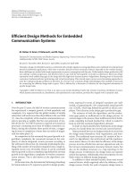
Figure 1.1 below illustrates this concept. UWB pulses spread energy over severalgigahertz range of frequencies, as opposed to traditional narrowband, which covers a
limited band of about 30 kilohertz. Cellular phones operate in the wideband, which covers
about 5 megahertz.
2
CHAPTER 1: INTRODUCTION
Energy
Narrowband, 30 kilohertz
Wideband, 5 megahertz
Ultra-wideband, several gigahertz
Frequency
Figure 1.1 Frequency & energy comparison for communication systems.
The definition of UWB evolves with time. The rule making of UWB was opened by FCC
in 1998. The resulting First Report and Order (R&O) that permitted deployment of UWB
devices was announced on 14 February and released in April 2002 [10], which unleashed
a very large bandwidth of 3.1-10.6 GHz to UWB transmissions. Three types of UWB
systems are defined in this R&O: imaging systems, communication and measurement
systems, and vehicular radar systems. Specifically, UWB characterizes transmission
systems with instantaneous spectral occupation in excess of 500 MHz or a fractional
bandwidth of more than 20%.
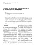
The bandwidth and spectral mask for indoor communication systems assigned by FCC is
illustrated in Figure 1.2. It can be seen that the FCC regulated power levels are very low
(below -41.3 dBm), which allows UWB technology to coexist with legacy services such
as IEEE 802.11a wireless local area network (WLAN), radar systems, etc., as well as
3
CHAPTER 1: INTRODUCTION
overlay with sensitive military and civilian services in adjacent bands such as global
positioning system (GPS) and federal aviation system (FAS). Cellular phones, for
example, transmit up to +30 dBm, which is equivalent to 10 7 higher power spectral
density (PSD) than UWB transmitters are permitted [11]. Currently the IEEE 802.15
Working Group is putting efforts to standardize UWB wireless radios for indoor
multimedia transmissions.
-40
UWB EIRP Emission Level in dBm
-45
-50
3.1
10.6
1.99
-55
-60
-65
GPS
Band
-70
Indoor Limit
Part 15 Limit
-75
0.96
10
0
1.61
Frequency in GHz
10
1
Figure 1.2 FCC regulated spectral mask for UWB indoor communication systems.
Based on the FCC regulation, UWB is mostly suitable for the short-range high-speed
4
CHAPTER 1: INTRODUCTION
applications among other wireless systems, as can be seen in Figure 1.3. From Shannon’s
theory [12],
C = 1.44 × W × log 2 (1 + SNR ) ,
(1.1)
where C standards for the channel capacity in bits per second, W represents the channel
bandwidth in hertz and SNR is the signal to noise ratio, the channel transmission rate
grows linearly with channel bandwidth but only logarithmically with SNR . In other
words, the channel capacity increases much faster as a function of bandwidth than power.
Thus UWB has the potential to offer high data rate (in several hundred megabit per
3G Cellular
2G/2.5G Cellular
10km
1km
100m
10m
Distance Coverage
cellular
second, Mbps) to emerging high-speed-demanding applications.
Figure 1.3 Operation distance and data rate of major wireless standards.
5
CHAPTER 1: INTRODUCTION
A comparison between a basic UWB transceiver and a conventional narrowband
transceiver is shown in Figure 1.4. The main difference between them is the saving of the
complex superheterodyne structure in a UWB transceiver. The transmission of UWB
waveforms can be free of sine-wave carriers (called “carrier-less short pulse” technique
[13]) and do not require any IF processing because they can operate in the baseband.
Data
Output
Data
Input
Modulator
PA
LNA
RF Filter
RF
BPF
RF
LPF
Demodulator
IF
(a) Typical narrowband transceiver architecture
Data
Input
Modulator
RF Filter
LNA
RF Filter
LPF
Demodulator
Pulse
Gegerator
Pulse
Generator
PRF
PRF
(b) Typical UWB transceiver architecture
Figure 1.4 Comparison of UWB and conventional NB transceiver architectures.
To characterize the UWB propagation channel, many responses have been received to the
Call for Contributions on UWB Channel Model [14]. Considering various proposals that
optimally chose the respective model parameters (such as mean excess delay, root mean
square (RMS) delay, mean number of significant paths etc) to best fit the observed data,
the IEEE 802.15.3a channel modeling task group has adopted a modified version of the
Saleh-Valenzuela (S-V) model for indoor channels [15]. The channel measurements
6
CHAPTER 1: INTRODUCTION
showed a clustering of the multipath arrivals which is best captured by the S-V model.
More details on the channel model will be discussed in chapter 3. Basically, the very wide
bandwidth of the transmitted pulse allows fine resolution of the multipath components.
This has both pros and cons. Fine delay resolution implies the potential for significant
diversity gains due to the large number of available paths. However, the total received
energy is distributed over a large number of paths, which means the receiver must be
capable of picking up and combining the multipath energy in a proper way. Normally a
Rake receiver is employed for this job.
In summary, occupying huge bandwidth by transmitting ultra short (in nanosecond scale)
information-baring pulses, UWB radio has unique advantages that have long been
appreciated by the radar and communications communities:
The wide bandwidth and high time resolution ability of UWB signals generally
make them more robust to multipath interference and channel fading;
A direct application of the Shannon's capacity theorem to an additive white
Gaussian noise (AWGN) channel shows that UWB systems offer a potentially
high data rate transmission capability with capacity increasing linearly with
bandwidth;
The low transmission power of the UWB signals translates into a RF signature
with a low probability of interception and detection (LPI/LPD), and also produces
minimal interference to proximity systems and minimal RF health hazards;
The fine time resolution of UWB systems makes them good candidates for
7
CHAPTER 1: INTRODUCTION
location and ranging applications (with precision at the centimeter level); and
More importantly, UWB systems have low system complexity and low cost, since
they are essentially baseband systems and can be made nearly "all-digital", with
minimal RF or microwave electronics.
8
CHAPTER 1: INTRODUCTION
1.2 Scope of the Thesis
The whole project is funded and supported by the Agency of Science, Technology and
Research (A-STAR) UWB Research program, jointly collaborated between Institute of
Microelectronics (IME) of Singapore and National University of Singapore (NUS).
The target of this thesis is to develop a practical and effective algorithm for low
complexity receivers of Impulse Radio (IR) UWB communication systems. The
theoretical performance analysis is carried out in details with a closed form bit error rate
(BER) expression derived. Extensive simulations have been done to verify the correctness
of the derivation.
The BER performance of the proposed architecture is also compared with conventional
Rake receivers to demonstrate its feasibility of implementations.
9
CHAPTER 1: INTRODUCTION
1.3 Organization of the Thesis
In chapter 1, the background of UWB communication systems is briefly introduced.
Chapter 2 presents some relevant works which have been done so far in this area. Two
normal UWB transmission schemes, IR and Multi-Band Orthogonal Frequency Division
Multiplexing (MB-OFDM), are described. Common Rake receiver structure is also given
in this chapter. The novel blind Rake (BRake) algorithm is proposed in chapter 3 with
detailed explanations on the signal model, channel model and receiver structure, followed
by in-depth performance analysis in chapter 4. Chapter 5 shows the simulation results
which have verified the theoretical derivation, as well as compared the performance of the
proposed algorithm and conventional methods. Conclusion remarks are given in chapter 6
with suggested future work.
10
CHAPTER 2: LITERATURE REVIEW
2 LITERATURE REVIEW
This chapter reviews some of the related literature works. Direct Sequence (DS) and
Multi-Band Orthogonal Frequency Division Multiplexing (MB-OFDM) are the two
mostly employed UWB transmission techniques. Impulse Radio (IR) is the simplest and
most frequently adopted form of DS-UWB, therefore it is the focus of this investigation.
MB-OFDM has a major advantage in flexible spectrum selection, but the transceiver
structure is complicated due to the presence of multiple frequencies. IR, on the other hand,
operates in the baseband and does not require any IF processing, which results in much
simplified receiver structure. Therefore IR scheme is adopted in this thesis. The impulse
shape and signal modulations of IR-UWB are then reviewed. The second order derivative
Gaussian monocycle and BPSK are chosen in our system.
Common Rake receiver structure is also reviewed in this chapter. Rake receivers are used
to capture multipath dispersed channel energy in wireless communication systems. All
Rake (ARake), Selective Rake (SRake) and Partial Rake (PRake) are commonly known
Rake types. Performance and complexity are trade-offs in considering using different
types of Rake structures. Channel state information (CSI) has to be provided for Rake
receivers to work effectively, but UWB channels are very difficult and costly to be
estimated in real time. This is why our BRake structure is proposed and developed.
11