Dual band FSK receiver and building block design for UWB impulse radio
Bạn đang xem bản rút gọn của tài liệu. Xem và tải ngay bản đầy đủ của tài liệu tại đây (1.67 MB, 108 trang )
DUAL-BAND FSK RECEIVER AND BUILDING
BLOCK DESIGN FOR UWB IMPULSE RADIO
MURLI UNNIKRISHNAN NAIR
(B. Eng. , McGill University)
A THESIS SUBMITTED
FOR THE DEGREE OF MASTER OF ENGINEERING
DEPARTMENT OF ELECTRICAL AND COMPUTER
ENGINEERING
NATIONAL UNIVERSITY OF SINGAPORE
2007
Name: MURLI U. NAIR
Degree: Master of Engineering
Department: Electrical and Computer Engineering, NUS
Title: Dual-band FSK receiver and building block design for UWB Impulse radio
I. ABSTRACT
A CMOS non-coherent impulse radio receiver implementing a dual-band
frequency
shift
keying
(FSK)
modulation
scheme
for
ultra-wideband
communication is presented. The quadrature direct-conversion architecture of the
receiver retains low-complexity operation while the added diversity gain of the
FSK modulation enables reliable demodulation at signal to interference ratio (SIR)
as low as –60dB. Several innovative circuit structures including an area and power
efficient UWB low-noise amplifier utilizing active inductors and a hybrid
topology mixer to extend operational bandwidth without compromising
conversion gain have been explored. In addition, a 4-bit R-2R DAC capable of
less than 0.5 LSB INL and DNL, a four-quadrant squarer with squaring gain of 65
and a dual threshold comparator with more than 700mV hysterisis and have also
been designed.
The fabricated receiver achieves a sensitivity of -88 dBm at a BER of 10-5
at 25 MHz data rate with an energy efficiency of 2.7 to 4.95 nJ/bit.
Keywords: ultra-wideband (UWB), receiver, low-noise amplifier, frequency shift
keying (FSK), digital to analog converter (DAC), active inductor
ii
ACKNOWLEDGEMENTS
I would like to take this opportunity to thank the many friends and colleagues
who have supported and challenged me during my post-graduate studies. Firstly, I
am deeply indebted to my supervisors, Dr. Zheng Yuanjin and Prof. Lian Yong
for their constant support and invaluable guidance. I am also grateful to the
Institute of Microelectronics, Singapore and its entire staff, especially in the
Integrated Circuits and Systems (ICS) group for giving me an opportunity to work
at their excellent facilities.
Thanks are also due to all the members of my research group who not only
provided insightful views and discussions, but also contributed by designing some
of the sub-blocks that are used in the system discussed in this thesis. Specifically,
I would like to acknowledge Mr. Ang Chyuen Wei, Ms. Fei Ting and Ms. Nina
Ann George for the designs of the 3-stage current reuse low-noise amplifier,
quadrature voltage controlled oscillator and the low-pass filter respectively. This
work would have been impossible without their contributions. I am also grateful
to Mr. Gao Yuan, Mr. Diao Sheng Xi and the rest of the ICS staff for the many
hours of discussions and instructions that I have received from them.
Lastly, I would like to reserve special thanks for my family and friends for
their constant love and support and I hope that this humble achievement will serve
as a small repayment for all their sacrifices.
iii
TABLE OF CONTENTS
ABSTRACT…………………………………………………………………
ii
ACKNOWLEDGEMENTS…………………………………………………
iii
SUMMARY…………………………………………………………………
vii
LIST OF TABLES…………………………………………………………..
ix
LIST OF FIGURES…………………………………………………………
x
LIST OF SYMBOLS AND ABBREVATIONS …………………………...
xiii
1. INTRODUCTION………………………………………………………..
1
1.1 Overview of UWB Communication………………………………… 1
1.2 Motivation…………………………………………………………… 3
1.3 Organization of thesis……………………………………………….. 4
2. RF system design fundamentals…………………………………………
6
2.1 Impedance matching ………………………………………………
6
2.2 Scattering parameters ……………………………………………
7
2.3 Noise Figure ………………………………………………………
8
2.4 Linearity and IIP3…………………………………………………
10
2.5 Signal to Noise ratio…………………………………………………
11
2.6 Minimum detectable Signal (MDS)……………. ………………...
12
2.7 Dynamic Range ……………………………………………………
12
3. Conventional UWB receiver architectures………………………….
14
3.1 Narrowband receiver overview ………………………………..
14
3.1.1 Common modulation schemes…………………………….
14
3.1.1.1 Binary Phase Shift Keying (BPSK)…………….
14
iv
3.1.1.2 Frequency Shift Keying (FSK)……………………..
3.1.2 Common receiver architectures …………………………
15
16
3.1.2.1 Direct Conversion (DC) receiver…………………
16
3.1.2.2 Super-heterodyne receiver……………………………
18
3.2 UWB receiver overview ………………………………………
19
3.2.1 DS-UWB receiver architectures ………………………..
20
3.2.1.1 Coherent receivers…………………………………..
20
3.2.1.2 Non-coherent receivers……………………………..
22
4. Proposed system architecture………………………………………
25
4.1 UWB Impulse based Dual-band FSK modulation………….
26
4.2 Proposed Receiver Architecture……………………………..
27
4.3 Mathematical model for proposed receiver system…………
30
5. Receiver Building Blocks design…………………………................
34
5.1 Low-noise amplifier…………………………………………..
34
5.1.1 Common wideband LNA topologies ……………………
35
5.1.2 UWB LNA utilizing Active Inductor ……………………
39
5.1.2.1 Active Inductor design……………………………..
39
5.1.2.2 LNA design …………………………………………
42
5.1.3 3-stage current reuse UWB LNA………….…………….
46
5.2 UWB Mixer……………………………………………………
48
5.2.1 Gate-source injection mixer …………………………….
49
5.2.2 Gilbert Cell mixer ……………………………………….
50
5.2.3 Hybrid Mixer ……………………………………………
51
5.3 Quadrature VCO ……………………………………………
54
5.4 R-2R Digital to Analog Converter ………………………….
55
5.4.1 R-2R Ladder ………………………………………….
.
57
5.4.2 Voltage mode R-2R DAC …………………………….
59
5.5 Low-pass Filter and IF Amplifier …………………………..
62
5.6 Squarer ……………………………………………………...
65
v
5.7 Differential to Single-ended (D-S) converter ……………....
67
5.8 Comparator ………………………………………………...
69
6. System Integration and Simulation results…….............................
72
6.1 System Simulation setup……………………………………
72
6.2 Layout considerations……………………………………….
74
6.3 Simulation and Measurement results……………………….
76
6.3.1 Integrated receiver simulation results ………………...
76
6.3.2 Receiver front-end measurement results ……………..
81
6.3.3 Integrated receiver measurement results ……………..
82
7. Conclusion and Future Directions ……........................................
85
7.1 Conclusions…………………………………………………..
85
7.2 Future Directions…………………………………………….
86
REFERENCE LIST………………………………………………......
87
APPENDIX A: Active Inductor based UWB LNA die photo ………
91
APPENDIX B: Dual-band UWB FSK receiver integrated front-end die photo 92
APPENDIX C: Dual-band UWB FSK fully integrated receiver layout…
93
APPENDIX D: Publication List ……………………………………….
94
vi
SUMMARY
Ultra-wideband technology is fast gaining popularity in high speed, short
range wireless communication and localization applications due to its extremely
low transmission levels and ability to share the congested 3-10 GHz
communication band with other existing narrow-band devices. However, due to its
unique pulse based implementation, the design of conventional I-UWB receivers
differs significantly from traditional radio systems and generally suffers from
added system complexity due to the additional circuit blocks needed for
synchronization and channel estimation requirements. In this thesis, an alternate IUWB receiver structure based on a novel system approach which incorporates the
unique benefits of UWB while at the same time reducing design complexity and
achieving better interference rejection is proposed and discussed.
A new dual-band FSK modulation scheme using conventional short
monocycle Gaussian pulses and the corresponding receiver system architecture
capable of implementing this scheme are described in detail. Based on these
system characteristics, required RF components are designed in Chartered
Semiconductor’s 0.18µm process and analyzed. Several building blocks required
for system implementation including an LNA, mixer, DAC, squarer and
comparator are designed and their functionality is analyzed in detail both
theoretically and through extensive simulation and measurements.
Active inductors are utilized in the LNA design in order to achieve a
vii
drastically reduced chip size of 0.05mm2 while maintaining wideband (3-5GHz)
operation with a gain of 15.1dB and noise figure (NF) between 4.95dB to 6.1dB
while consuming 7.1 mW. A hybrid UWB mixer structure which combines the
gate-source injection and Gilbert cell topologies in order to extend the operational
bandwidth without compromising conversion gain has been implemented. It can
achieve greater than 5.5dB conversion gain with 11dB NF and excellent isolation
over the entire 3.1-4.8 GHz bandwidth. A 4-bit R-2R resistor ladder structure is
used to implement the DAC which is capable of less than 0.5 LSB INL and DNL
performance with less than 25ns settling time for maximum output voltage step
(0-1.8V). A four quadrant baseband squarer with a squaring gain of 65 and input
bandwidth of 210MHz is also utilized. The comparator has a dual threshold
operation with more than 700mV hysterisis and is also capable of excellent signal
integrity and load driving capabilities.
As the final objective of this work, the various component blocks are laid out
and are used to realize the proposed receiver system in 0.18µm CMOS
technology. The feasibility of implementation of the proposed I-UWB system and
its functionality are confirmed and its unique ability to reject in-band interference
is also demonstrated. The receiver can achieve a voltage sensitivity of up to 90μV
and IIP3 of -32 dBm at a data-rate in excess of 25 MHz while consuming between
48 to 84 mA current from a 1.8V source.
viii
LIST OF TABLES
Table I:
Table II:
Comparison of presented work with other published LNA designs
utilizing Active Inductors ……………………………………
46
Overall simulated receiver performance……………………..
77
Table III: Summary of measured receiver performance and benchmarking against
state of the art in publication………….……………………..
ix
84
LIST OF FIGURES
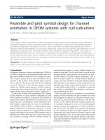
Fig. 1.1 UWB capacity versus other WLAN technologies…………………..
2
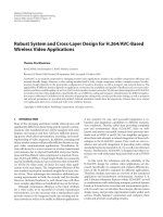
Fig. 1.2 FCC Spectral Mask for UWB Communication Systems……………
3
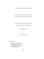
Fig. 2.1 Conjugate matching of reactive impedances using a matching network 7
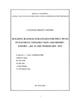
Fig. 2.2 S-parameter representation of an N-port network…………………..
8
Fig. 2.3 3rd order intermodulation behavior and IIP3 definition……………..
11
Fig. 2.4 Graphical definition of the dynamic range………………………….
13
Fig. 3.1 BPSK Modulation……………………………………………………
15
Fig. 3.2 FSK Modulation……………………………………………………..
16
Fig. 3.3 Direct Conversion receiver architecture……………………………..
17
Fig. 3.4 Super-heterodyne receiver architecture………………………………
19
Fig. 3.5 Basic coherent UWB receiver architecture………………………….
21
Fig. 3.6 Non-coherent Transmitted Reference UWB receiver architecture…..
22
Fig. 3.7 Non-coherent Auto-correlation UWB receiver architecture………....
23
Fig. 4.1 Wideband FSK Modulation sub-band allocation…………………….
26
Fig. 4.2 Proposed receiver architecture for UWB dual-band FSK……………
27
Fig. 4.3 Gaussian monocycle pulse in time domain…………………………..
30
Fig. 4.4 Analytical UWB dual FSK system model……………………………
31
Fig. 5.1 Common LNA topologies (a) Resistive termination (b) Common gate
(c) Shunt-series Feedback. (d) Common source with inductive degeneration..
36
Fig. 5.2 Small signal model of a source degeneration amplifier……………...
38
Fig. 5.3 (a) Active inductor structure; (b) Small signal equivalent…………… 40
Fig. 5.4 High frequency performance of the active inductor………………….
41
Fig. 5.5 Overall three stage LNA schematic…………………………………..
43
Fig. 5.5 (a) Individual and staggered stage gains (b) Measured (---) and simulated
( ) S21 and S11 (c) Measured Noise Figure (d) Measured Linearity………..
44
Fig. 5.6 3-stage current reuse UWB LNA…………………………………….
47
x
Fig. 5.7 (a) Gate source mixer architecture (b) Associated 4 quadrant cancellation
scheme………………………………………………………………………… 49
Fig. 5.8 Gilbert cell mixer architecture………………………………………..
50
Fig. 5.9 Hybrid mixer architecture…………………………………………….
52
Fig. 5.10 Hybrid mixer conversion gain………………………………………
53
Fig. 5.11 (a) LO-RF Isolation (b) RF-IF Isolation (c) LO-IF Isolation
(d) Noise Figure………………………………………………………………
53
Fig. 5.12 QVCO structure……………………………………………………
54
Fig. 5.13 (a) Gain error (b) Offset error (c) DNL representation (d) INL
representation…………………………………………………………………
56
Fig. 5.14 N-bit R-2R ladder in voltage mode………………………………...
57
Fig. 5.15 R-2R ladder with [0,0,..,bn=1, 0,0… 0] input……………………...
57
Fig. 5.16 R-2R ladder equivalent circuit …………………………………….
58
Fig. 5.17 Proposed R-2R ladder DAC circuit………………………………..
60
Fig. 5.18 Loaded DAC output for (a) Monotonic step input (b) Maximum
step input……………………………………………………………………..
61
Fig. 5.19 Op-amp Gain and phase response…………………………………
61
Fig. 5.20 First order Gm-C filter…………………………………………….
62
Fig. 5.21 Bi-quadratic Gm-C filter ………………………………………….
62
Fig. 5.22 Intermediate Frequency (IF) Amplifier……………………………
63
Fig. 5.23 Frequency response of (a) 5th order Elliptic LPF (b) Filter +
IF Amplifier………………………………………………………………….
64
Fig. 5.24 Squarer architecture………………………………………………..
65
Fig. 5.25 Squarer transient response with a filtered pulse train input………..
67
Fig. 5.26 Differential to Single-ended converter…………………………….
68
Fig. 5.27 (a) CMOS Schmitt trigger and (b) associated hysterisis
Characteristics………………………………………………………………..
70
Fig. 5.28 Schmitt trigger with 4-stage inverter chain………………………...
71
Fig. 5.29 (a) Comparator hysterisis and (b) propagation delays……………...
71
Fig. 6.1 System front-end simulation setup…………………………………..
73
xi
Fig. 6.2 System back-end simulation setup…………………………………… 73
Fig. 6.3 Simulated receiver performance (Band 2 demodulation)…………….
78
Fig. 6.4 Simulated receiver performance in clean channel
(Band 2 demodulation)………………………………………………………... 79
Fig. 6.5 Simulated receiver demodulation and interference rejection performance
(Band 1 demodulation)………………………………………………………... 80
Fig. 6.6 Measured receiver front-end performance…………………………… 81
Fig. 6.7 QVCO I and Q single-ended outputs at 3.6 GHz ……………………
82
Fig. 6.8 Receiver demodulated output of UWB FSK signal in Band ‘1’ ……… 83
Fig. 6.9 Receiver demodulated output of UWB FSK signal in Band ‘2’ ……… 84
xii
LIST OF SYMBOLS AND ABBREVATIONS
CL
Load Capacitance
Ids
Drain to source current of a MOSFET
Iout
Output current
M
Symbol for MOS transistor
gmA
Transconductance of MOSFET MA
ro
Drain source resistance of mos transistor
Zin/out Input/ Output resistance
Vctrl
Control voltage for QVCO
VDD
Positive supply voltage
Vout
Output voltage
VT
Threshold Voltage
ωp
Pole
Av
Voltage Gain
Vds
Drain-source voltage of MOSFET
K
Transconductance parameter of MOSFET
μ0
Mobility of MOSFET
Cox
Unit gate capacitance of MOSFET
W/L
Aspect ratio of MOSFET
xiii
ADS
Advanced Design System
CMOS
Complementary MOS
DLL
Delay Lock Loop
FCC
Federal Communication Commission
IC
Integrated Circuit
ICS
Integrated Circuit and Systems
IME
Institute of Microelectronics
MOSFET Metal-Oxide Semiconductor Field-Effect Transistor
NMOS
N-channel Metal Oxide Semiconductor
NUS
National University of Singapore
RF
Radio Frequency
SNR
Signal to Noise Ratio
UWB
Ultra Wide band
xiv
Chapter 1
Introduction
1.1 Overview of UWB Communications
Over the past decade, the notion of traditional wired telecommunication which has
prevailed for over half a century has become obsolete and is rapidly being replaced by
wireless communication systems. From global applications like cellular telephones,
wireless internet networks and Global Positioning System (GPS) to personal applications
like personal digital assistants (PDA) and Bluetooth, wireless technology is gaining a
presence in every facet of our lives. However, to sustain this presence, new wireless
technologies are required that can achieve higher speeds and higher data-rates so as to
meet the ever changing demands of today’s devices.
Ultra wide-band (UWB) is an emerging wireless technology which shows great
potential for short range, high data-rate communication and localization applications. The
biggest advantages of the UWB technology are derived from the fact that it utilizes a
much wider bandwidth and operates at much lower power levels than traditional
narrowband systems. This statement is supported by the Shannon-Hartley Theorem (Eq.
(1.1)) for channel capacity which states that in an additive white Gaussian noise (AWGN)
environment, the maximum channel capacity (C) is directly proportional to the bandwidth
(B) of the channel and to the logarithm of signal to noise ratio (SNR).
C = B log 2 (1 + SNR)
(1.1)
This means that the wide operational bandwidth of UWB communication allows it to
achieve higher data-rates more cost-effectively (i.e. without an exponential rise in signal
1
power) than narrowband systems while at the same time the very low transmission levels
allow co-existence between UWB and existing standards. The unique features of UWB
technology are especially beneficial in short range applications where it can achieve
much higher channel capacities than existing standards as shown in Fig. 1.1 [3].
Moreover, the narrow pulse based nature of UWB makes it much less immune to
multipath distortion due to destructive fading than narrowband systems.
UWB technology is at present defined by the Federal Communications Commission
(FCC) as any wireless transmission scheme that occupies a fractional bandwidth of more
than 20% with respect to its center frequency or more than 500 MHz of absolute
bandwidth. More specifically, the FCC has approved the unlicensed deployment of UWB
in the 3.1-10.6 GHz range subject to strict regulations that limit the emitted power
spectral density (PSD) measured over a 1 MHz bandwidth to below -41.3 dBm as shown
in Fig. 1.2 [1].
Fig. 1.1 UWB capacity versus other WLAN technologies
2
-41.3 dBm
UWB Passband (3.1-10.6 GHz)
Fig. 1.2 FCC Spectral Mask for UWB Communication Systems
1.2 Motivation
Due to its unique features, in recent years UWB has found applications in high speed
short range wireless data connectivity between several remote hosts as well as in sensor
networks and precision localization and ranging. With the significant interest being
shown by the research community and a concerted effort on the part of the regulatory
bodies to finalize the standards, the future is looking very bright for UWB technology
and it is tipped as having potential for realizing an exciting new set of applications that
are presently not being fulfilled by other wireless short range technologies currently
available (e.g., 802.11 LANs (Local Area Networks) and Bluetooth PANs (Personal area
networks)).
3
The key to successful implementation of any telecommunications platform in
mainstream applications is the cost feasibility, robustness and reliable performance of the
end product. These demands are especially difficult to meet at the high operating
frequencies of UWB devices and pose unique challenges to circuit designers.
In this thesis, a UWB receiver architecture which utilizes a novel dual-band FSK
modulation scheme for a UWB impulse Radio (IR) system is proposed. The design of the
building blocks has been done in the 0.18μm CMOS technology provided by Chartered
Semiconductors foundry. All the constituent components have been built in silicon
CMOS technology instead of using specialized III-V technologies like GaAs or SiGe
which provide better RF performance in terms of output power, linearity and phase noise.
This choice is made because silicon CMOS in the most mature and cost effective
technology and at the same time guarantees better yields and a larger scope for future
integration with baseband and digital processes.
1.3 Organization of the Thesis
Chapter 2 is dedicated to briefly introducing some fundamental RF design concepts to
facilitate the understanding of the rest of the thesis.
In chapter 3, popular receiver architectures for conventional narrowband well as DSUWB systems are briefly reviewed. The related Binary Phase Shift Keying (BPSK) and
Frequency Shift Keying (FSK) modulation schemes are also discussed.
In Chapter 4, a new modulation scheme for I-UWB applications, ‘dual-band UWB
FSK’ is proposed and the quadrature receiver designed to implement this scheme is
discussed
4
Chapter 5 concentrates on design of the various UWB receiver building blocks for the
required application and their performance. Blocks including an LNA, mixer, DAC,
squarer and comparator are discussed in detail. Blocks designed by group members are
briefly introduced.
In chapter 6, detailed simulation results of the aforementioned receiver system are
shown. Measurement results from tests carried out on the fabricated front-end alone are
also given
Conclusions drawn from this work are given in Chapter 7 along with suggestions for
future work.
5
Chapter 2
RF system design fundamentals
Even though the receiver structures used in UWB telecommunication have several
parallels with more conventional low frequency narrowband systems, the design of the
various required components is radically different due to the unique demands of RF wide
bandwidth operation. In order to understand these challenges better, this chapter is
dedicated to briefly explaining some of the key RF design parameters and the ways in
which these specifications are met.
2.1 Impedance matching
In order to achieve the best possible system performance in any electrical system, it is
essential to ensure that there is a maximum transfer of power between the output of each
block and the input of the subsequent block. In the case of passive devices with fixed
input and output resistances, this condition can be achieved by making the load and
source resistances the same. However in the case of active devices with reactive input
and output impedances, the condition for maximum power is met when the source and
load impedances are complex conjugates of each. In all practical electrical structures,
including the circuit blocks that will be discussed in this thesis, the latter situation applies
and hence special attention needs to be paid to ensure that proper impedance matching is
obtained.
6
However, since the inherent reactive properties of successive blocks almost never
match each other, it is often necessary to add an impedance matching network to achieve
maximum power transfer. As shown in Fig 2.1, in most cases an impedance matching
network is a specific configuration of suitably chosen reactive components (capacitors or
inductors) that buffer successive stages in a circuit chain so that the effective load and
source impedances seen by each block satisfy the maximum power transfer requirement.
Matching Network
RS + jXS
ZinS = RS – jXS
ZinL = RL – jXL
RL
+
jXL
Fig. 2.1 Conjugate matching of reactive impedances using a matching network
2.2 Scattering Parameters
One of the biggest challenges in RF circuit design is posed by the fact that at high
frequencies, the impedance of even small reactive components becomes significant and
hence cannot be neglected. This means that all parasitic elements of the transistors,
transmission lines, bonding wires etc. need to be included in the design process to
achieve accurate results. But in doing so, the process of circuit design from basic design
equations becomes overly complex and intractable. Scattering parameters are an essential
circuit design tool that allows the accurate and efficient characterization of even the most
complex component in a way that simplifies the design steps considerably.
7
The S parameter representation of any N-port electrical network is an N by N matrix
as shown in Fig 2.2 which characterizes the network in its entirety as an N-port ‘black
box’ based on its response to various steady state small signal stimuli. Various circuit
performance parameters can be easily derived directly from this simple and handy
representation. The S-parameter based metrics used extensively in the design and analysis
of the 2-port circuit blocks described in this thesis are as follows:
Scalar logarithmic gain, A = 20 log10 | S 21 | dB
Input Return Loss, RLin =| 20 log10 | S11 || dB
Output Return Loss, RLout =| 20 log10 | S 22 || dB
Reverse Isolation, Arev = 20 log10 | S 21 | dB
Port 1
S11 S12 …
Port 2
S21
Port 3
S31
S1N
.
Port N
SN1 SN2 .. ..
SNN
Fig. 2.2 S-parameter representation of an N-port network
In all the following S-parameter usage, a characteristic impedance of 50Ω is assumed.
2.3 Noise Figure
Noise can be seen as any undesired interference signal present in a system within the
pass band of the desired signal. Noise adversely affects the signal detection capability of
the system. Several forms of noise have been identified in electrical devices including
8
thermal noise and flicker noise. Noise can be characterized as a random variable with
Gaussian distribution and zero mean and is generally quantified as a root mean square
(RMS) value over a specified time interval as
VnRMS =
T0 +TM
∫ [v
n
(t )] 2 dt
(2.1)
T0
where vn(t) is the instantaneous noise voltage variable and T0 to T0+TM is the time
interval of interest.
The source of noise in conductors is the inherent random motion of charge carriers. In
particular, the two major sources of noise in any RF circuit are the thermal noise of
resistors and transistors. These can be quantified as follows [11]
2
VnRES = 4kTRB
(2.2)
VnMOS = 4kTγg m B
(2.3)
2
where k is Boltzmann's constant (1.38 x10⁻¹² J/ oK), T is the absolute temperature in oK, B
is the noise bandwidth (Hertz) of the system and VnRES and VnMOS represent the RMS
thermal noise voltages of a resistor R and a MOSFET in saturation with transconductance
gm and γ represents a technology dependant coefficient (γ = 2/3 and > 4/3 for long and
short channel devices respectively).
In circuit design, noise figure (NF) is a measure of the degradation of the signal to
noise ratio (SNR), caused by components in the RF signal chain. In other words, the
noise figure is the ratio of the total output noise power of a device to the portion thereof
attributable to the noise at the input from the source.
NF = 10 log10
SNRin
SNRout
(2.4)
9
NF is an important metric for almost all radio components and low NF is essential for
high system sensitivity.
2.4 Linearity and IIP3
All devices are non-linear to some extent and it is unrealistic to expect even the most
carefully designed circuit to behave perfectly linearly over all input power levels.
Therefore the transfer function of a device can be modeled by Taylor series expansion as
2
Vout = k1Vin + k 2Vin + k 3Vin 3 + ...
(2.5)
where k1..n are known constants. Now assume that the device is excited by an input signal
consisting of two adjacent frequency tones so that Vin = A cos ω1t + A cos ω 2 t . Then by
expanding the output term and applying some basic trigonometric identities, we find
Vout = α 1 A(cos ω1t + cos ω 2 t ) + α 2 A 2 (cos( ω1 + ω 2 )t + cos( ω1 − ω 2 )t )
− α 3 A 3 (cos(2ω1 − ω 2 )t + cos(2ω 2 t − ω1t ) + ..) + ..
(2.6)
where generally α1>α2>α3>…
As seen in Eq. (2.6), for higher power levels, the output of the device gets more and
more distorted by higher order harmonics. Since the 3rd order product components, 2ω2-
ω1 and 2ω1-ω2 lie in close proximity to the desired frequency components, they merit
special attention. Fig. 2.2 [12] illustrates the behavior of the third-order intermodulation
products as input power level increases. With the input and output powers plotted on a
log scale, the intermodulation product amplitudes follow straight line trajectories with
gradients proportional the order of the products. By extrapolating these lines, a theoretical
threshold called Input referred 3rd order intermodulation point (IIP3) can be derived
10
which signifies the maximum input power level below which the fundamental tones are
stronger than the 3rd order harmonics. IIP3 serves as a measure for the device’s linearity.
Fig. 2.3 3rd order intermodulation behavior and IIP3 definition
For N cascaded stages, the IIP3 of the system (IIP3total) can be expressed as:
G G .....Gn −1
G1
GG
1
1
=
+
+ 1 2 + ...... + 1 2
IIP3total IIP31 IIP3 2 IIP33
IIP3 n
(2.7)
Where IIP3n is the IIP3 of the nth stage, Gn is the power gain of the nth stage.
2.5 Signal to Noise ratio
SNR is a measure of the clarity of a signal. It is defined as the ratio of a signal power
to the background noise power corrupting the signal and can be written as
SNR =
Psignal
Pnoise
(2.8)
11