Encapsulation issues in organic light emitting diodes
Bạn đang xem bản rút gọn của tài liệu. Xem và tải ngay bản đầy đủ của tài liệu tại đây (2.76 MB, 87 trang )
Chapter 1 Introduction
1.1 Introduction to organic light-emitting diode (OLED)
1.1.1 OLED device
Since Tang and Van Slyke first reported high efficiency bi-layer OLED in 1987 [1],
much effort has been made to improve their performance. The emerging organic lightemitting diode technology holds considerable promise for the smooth panel display
industry. This is why a number of research institutes and commercial companies have
formed collaborations to accelerate the development of suitable mass-production
processes and equipment for OLED devices. In particular, conjugated polymer OLED
technology has attracted much of the interest recently due to its low cost of processing.
The key to OLED technology is the development of organic semiconductor
materials,which is also a crucial starting point for so-called "plastic electronics". During
the 1980s, Kodak and UK-based start-up Cambridge Display Technology (CDT)
developed displays that formed luminescent images when electric currents were passed
through thin layers of organic materials based on small organic molecules and conjugated
polymers to generate light. In effect, each pixel in the display behaved in the same way as
a miniature light emitting diode (LED).
1
1.1.2 Advantages of OLED over LCD display technology
An OLED is an electronic device made by placing a series of organic thin films
between two conductors. When an electrical current is applied, light is emitted by a
process called electroluminescence as electrons and holes injected from the cathode and
anode respectively, recombine in the organic light-emitting layer.
hν
Figure 1.1 OLED structure showing injection of electrons from the cathode and holes from the ITO anode, and their
recombination in the electroluminescent (EL) layer.
OLED displays are lightweight, durable, power efficient and ideal for portable
applications. OLED display fabrication has fewer process steps and also uses lower-cost
materials compared to liquid crystal display (LCD). It is believed that OLEDs can replace
2
the current LCD technology in many display applications due to the following
performance advantages over LCD:
•
Greater brightness
•
Faster response time for full motion video
•
Wider viewing angles
•
Lighter weight
•
Higher power efficiency
•
Broader operating temperature ranges
•
Greater cost-effectiveness
1.1.3 Lifetime challenges
The lifetime of a display is the number of hours that the display is functional [2]. It
can be classified into storage lifetime and operational lifetime. Storage lifetime denotes
how long it would be possible to store the display in the absence of current. Operational
lifetime is usually defined as the time for the electroluminescence of the OLED to
degrade to half its initial brightness (typically 100 cd/m2).
Although some of the properties of OLED match, and in some cases, surpass those of
current LED’s, the fact remains, however, that the lifetime in these devices needs to be
further improved for long-term consumer applications [3]. Currently, the only products
3
having displays based on OLEDs are “short-term” commodity items such as cell phones,
car stereo systems, and digital camera displays. Most recently, Seiko Epson has reported
a 40-inch TV screen prototype made from conjugated polymer OLED.
Considerable research had been done to identify the causes of degradation, which
shortened the lifetime of the OLEDs [2]. The most prominent morphological change
observed in some degrading devices was the de-lamination of the cathode material [4].
The de-lamination appeared in electroluminescence micrographs as non-emissive spots.
These non-emissive areas were sometimes referred to as ‘‘dark spots’’ or ‘‘black spots’’ [5]
(although they do not look ‘‘black’’ under external illumination, see below). The nonemissive spots were attributed initially to local heating caused by short circuits which led
to the formation of pinholes and local ablation [6] or local fusion of the metallic cathode
[7]. Recent studies [8] revealed that the non-emissive spots had domelike structures
termed ‘‘bubbles’’ filled with gases (mostly oxygen) presumably evolved in the course of
electrochemical and photo-electrochemical processes in the presence of water vapor [9,
10]. According to some recent reports [5, 11], the bubbles originated from pinholes in the
metallic electrode when the device was powered up in the presence of atmospheric
humidity. In a recent report on state-of-the-art devices, the hole-injecting conducting
polymer layer was found to be locally doped in the black spot, which pointed to an
electrochemical degradation process driven by electrical current in the presence of
moisture [12].
4
1.2 OLED device fabrication process
1.2.1 OLED materials
OLED materials for displays can be classified into two main types, each of which has
its own distinct fabrication process and unique set of advantages and limitations.
1) Small organic molecules------This approach involves vacuum batch deposition of
small organic molecule material layers onto a glass or silicon backplane. The technology
is well proven but currently only suits mass-production of small or medium-sized
displays up to about 15 inches in diameter. The fabrication of larger displays is hindered
by the shadow mask that is used to define the micron sized pixels of the display.
2) Conjugated polymers------The advantage of conjugated polymer light-emitting
display (PLED) materials is their solubility in organic solvents, allowing them to be
deposited onto a glass or flexible plastic substrate using spin-coating or ink jet printing.
Conjugated polymer technology enables the fabrication of larger displays as compared to
small-molecule OLED, as there is no need for shadow masking or vacuum deposition
processing. PLED displays can also be operated at lower voltages and are more powerefficient than those based on small organic molecules.
5
1.2.2 Display fabrication
OLED displays can be made using four simple steps:
1) Substrate preparation. The first step is the preparation of the substrate, also
known as the backplane. Indium tin oxide (ITO) coated glass is the substrate used for
passive matrix display fabrication. ITO sputter deposition is carried out in a vacuum
chamber and film patterning in a class 100 yellow room.
2) OLED fabrication. The next step is the fabrication of the OLED part of the
display. This step involves the spin-coating or printing, deposition of the hole transport
layer (HTL), electroluminescence (EL) layer and electron transportation layer (ETL).
Finally, the cathode electrode is deposited by a thermal evaporation process.
3) Encapsulation. To protect the OLEDs from being exposed to water vapor and
oxygen, the display is hermetically sealed in a protective package. This is essential to
maximize the display's performance and lifetime.
4) Assembly. Finally, the driving circuits that drive each pixel are wired up to the
display.
An example of such a display fabricated in IMRE in our work using a blue-emitting
polymer is shown in Fig. 1.2.
6
Figure 1.2 IMRE matrix blue OLED display (100 × 32 pixels).
1.3 Objective of the thesis
OLED technology offers the prospect of realizing flexible displays on plastic
substrates using roll-to-roll manufacturing processes. One of the biggest challenges to the
OLED display industry is not competition from the incumbent LCD industry but from
water vapor and oxygen. The materials used in small organic molecule and conjugated
polymer OLED are vulnerable to degradation by oxygen and water vapor, which can
trigger early failure. Sealing of the OLEDs from atmospheric oxygen and water vapor is
typically accomplished with a glass or metal lid attached to the display substrate using a
7
bead of ultraviolet (UV) cured epoxy. Such an encapsulation technique is not viable for a
flexible display, since low-moisture permeability epoxies are rigid. The obvious solution,
a plastic or thin film encapsulation----is non trivial. Plastics are permeable materials,
often with holes many microns in diameter that allow water vapor and oxygen to
permeate through. The barrier specification required for OLED displays is unclear, since
the mechanism of long-term degradation is still a subject of debate [13]. However, it is
clear that a stable OLEDs requires a moisture barrier which transmits < 10-5 g/m2/day of
water vapor [14]. All conventional vapor deposited barrier films are therefore inadequate
for OLED applications by several orders of magnitude.
Normally an organic and inorganic composite structure is used in OLED
encapsulation. The quality of encapsulation depends on the materials, surface topography
and the adhesion between the organic and inorganic layers. This thesis focuses on issues
in encapsulating organic light-emitting diodes with thin films.
Other than the quality of the encapsulation film, the surface roughness is also a factor
limiting the stability and the efficiency of the OLEDs [13]. Reducing the surface
roughness of the ITO reduces the area of adsorption sites for water vapor and thereby
extends the lifetime of the OLED device. Better encapsulation could also be obtained
with reduced surface roughness. Reactive ion etch (RIE) planarization of the indium tin
oxide (ITO) substrate, and associated changes in electrical, optical properties and
morphology in the device are thus investigated in this thesis. Understanding the
relationship between the surface roughness and lifetime of the OLED devices, allows
8
improvements in the manufacturing process to be made to achieve better stability of the
organic layers and the cathode. With improvements in encapsulation and efficiency of
OLED devices, mass commercial OLED production would be possible.
1.4 Organization of the thesis
Chapter 2 reviews current research interest in lifetime and encapsulation of OLED.
Oxygen and water vapor are the two main known agents leading to degradation of OLED
devices.
Chapter 3 describes the experimental techniques we used to fabricate the OLED
devices, measure the ITO surface parameters after RIE treatment and evaluate the various
fabrication processes relating to encapsulation of OLEDs.
Chapter 4 investigates the planarization effect of ITO surface using RIE. Reducing
the surface roughness improves OLED electrical performance and also reduces the water
vapor permeation through the interface between ITO and the encapsulation film.
Chapter 5 describes laser ablation as a method to realize 300-micron sized pixels.
This method avoids the formation of photo-resist mushroom structures which traps water
vapor. The micron sized spikes along the cathode runners formed during laser ablation
however poses a challenge to thin film encapsulation. Some methods to address these
post ablation spikes are discussed in this chapter.
Chapter 6 describes the use of multi-layer encapsulation to improve the barrier
properties to oxygen and water vapor. Subsequently the barrier film was used to
9
encapsulate conjugated polymer and small organic molecule OLED devices to investigate
the effect of barrier film encapsulation on device lifetime.
Chapter 7 summarizes the thesis and briefly describes possible future work.
10
Chapter 2 Literature Review
Contributing factors to the degradation of device performance over time include
reaction of organic materials with the cathode and its de-lamination, indium diffusion into
the organic layer, inter diffusion, chemical degradation, and crystallization of the same.
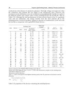
Careful engineering of device fabrication by manipulating different parameters such as
the purity and choice of materials, the rate of film growth during organic layer deposition,
the vacuum under which devices are fabricated and encapsulation have improved device
performance [15]. This thesis however is focused on the issues in encapsulating OLED
device, namely the effect of surface roughness and topography on encapsulation and
developing a barrier stack to improve the lifetime performance.
Oxygen and humidity are now believed to be the most important factors for
degradation of the OLED device. It is very important to understand how oxygen and
humidity penetrates the encapsulation layer and react with the organic film and cathode
layers. Firstly techniques important to OLED fabrication and encapsulation are reviewed.
This is followed by a review of OLED degradation and lifetime. Lastly experimental
methods used to study water vapor permeation in encapsulation films are reviewed.
2.1 OLED fabrication process
There are two ways to fabricate an OLED display. One way uses solution based
conjugated polymers. The other way employs vacuum deposition of small organic
11
molecules. The current method involved in making passive matrix display uses photo
resist ribs which are traps for water as described by Nguyen [16]:
Starting with ITO coated glass substrates, rows are obtained by etching the
lithographically patterned ITO layer. Since the sensitivity of the organic layers to
chemicals and humidity does not allow patterning of the metallic top contact after
deposition, a different approach has to be used to pattern the organic and cathode layers.
In situ photo resist shadow mask can be used to separate adjacent cathode rows. But the
photo resist barriers have a mushroom structure with high aspect ratio (Fig. 2.2), which
could seriously impact the backend thin film encapsulation process. Such photo resist
barrier ribs are also sources of traps for solvent and water vapor, which would contribute
to degradation of the OLED.
2 µm
Recess sites
Figure 2.1 Scanning electron microscope (SEM) image of a completely processed photo resist barrier.
12
Two obvious recess sites are showed under the mushroom structure. These sites can
act as trap sites for water vapor or solvent.
2.2 Oxygen plasma treatment of ITO surface
ITO has been by far the common choice for OLED anode materials, due to the
availability, good transparency and low resistance, and also to the ease with which it can
be patterned [17]. Among the many surface treatments of ITO, oxygen plasma treatment
is one of the most common techniques. It has been reported that oxygen plasma treatment
could effectively remove the surface carbon contamination, increase the work function of
ITO, which may lead to a lower energetic barrier for hole injection at the ITO/polymer
interface [18].
Cacialli reported that oxygen-plasma yielded the highest work function for a 10
minutes treatment, the smoothest surface, and the lowest surface resistance. Higher work
function was particularly attractive for improving injection of holes into the organic
semiconductors [19]. In conjugated polymer LED, conducting PEDOT [Poly (styrene
sulfonate)-doped poly (3, 4-ethylene dioxythiophene)] are directly spin-coated or printed
from water dispersion onto the surface-treated ITO. In this regard Cacialli noted that
oxygen-plasma induced the most polar surface leading to most uniform spreading of thin
films of polar polymer solutions in order to achieve a better adhesion at the ITO/polymer
interface [17].
Zhu demonstrated the enhancement in hole injection in device made with oxygen
13
treated ITO anode. The best EL performance was found in the PLED made with an ITO
anode treated with an oxygen flow rate of 60 sccm used in their study [18].
Since oxygen plasma treatment may improve the adhesion between ITO and polymer,
which led to better electrical performance of OLED device, oxygen reactive ion etch
(RIE) was explored for the pre-treatment of ITO anode in this thesis.
2.3 Current encapsulation techniques
Normally thick glass and epoxy were used for OLED encapsulation [20]. Fig. 2.3
shows the structure of the OLED device encapsulated using a glass lid and perimeter
epoxy seal. The function of the desiccant (usually, calcium oxide or barium oxide) is to
absorb the possible water vapor trapped in the metal can encapsulation.
OLED layers
and cathode
Glass
Epoxy
adhesive
Membrane
Stainless
steel can
desiccant
Figure 2.2 Schematic of thick glass encapsulated OLED device.
14
The flexibility of both small organic molecule and conjugated polymer OLED
encouraged their use of these materials in flexible displays [21]. OLED displays on
flexible plastic substrates have been reported [22]. However lifetime was short.
Development of a long-lived flexible OLED display on plastic substrate would therefore
have to overcome two major challenges: preventing moisture and oxygen diffusion into
the display area through the bottom/substrate and also through the top cathode.
Chwang described encapsulated passive matrix OLED displays on flexible plastic
substrates using a multilayer barrier encapsulation technology [23]. The flexible OLED
displays were based on highly efficient electro-phosphorescent OLED technology
deposited on barrier coated plastic substrate and were hermetically sealed with an
optically transmissive multilayer barrier coating (Barix encapsulation) (Fig. 2.3). A
lifetime of 2500 hours was achieved with a 5 mm2 encapsulated flexible OLED test diode.
15
Figure 2.3 Fracture cross-section SEM of generic Barix film (Cited from Vitex Company).
2.4 OLED degradation
The degradation of a non-encapsulated conjugated polymer-based LED was
accompanied by the appearance of strong fluctuations, in the radiance and in the film
resistance [20]. There was a correlation between the morphological changes which
occurred during the degradation process and the strong fluctuation.
Morphological changes observed during OLED degradation showed two distinct
phases. First, there was formation of ‘‘bubbles’’ at the metal–polymer interface due to
delamination of the polymer film from the metal surface. Second, carbonized areas in the
form of ‘‘dark spots’’ were formed. Fig. 2.4 shows an image of the same sample under
external illumination from the side of the ITO anode after a complete failure. Defects in
16
the form of ‘‘dark spots’’ can be observed.
100 µm
Figure 2.4 Micrographs of the device under external illumination: viewed through the ITO glass displaying dark spots.
The inhibition of bubble formation when the device was operated in the presence of
an inert atmosphere supported the idea [5, 8] that humidity and/or air played a very
important role in this initial delamination. Recent mass-spectrometric study of the bubble
contents [24] revealed the presence of mostly oxygen and some hydrogen beneath the
delaminated aluminum film. It was suggested that the electrode swelling was due to
gaseous products produced in electrochemical or photo-electrochemical reactions. A
thermally activated reaction between metal electrodes and the emitting polymer was
contemplated by Salaneck et al. [25].
After the initial bubble formation, the injected current was significantly higher in the
17
perimeter area surrounding the bubble due to local electric field amplification at the
edges. The large currents flowing through these areas carbonized the polymer, leading to
fusion of the electrodes [7]. Indeed, it was well known that some degraded devices show
a direct short.
2.5 The lifetime of OLED
The lifetime of OLED device is defined as the time that OLED device luminance
decays to half initial point (L0 ~ 100 cd/m2) [2]. Fig. 2.5 indicates lifetime curves for
OLED encapsulated in different ways.
Figure 2.5 Normalized lifetime data under dc drive for an OLED [25].
18
It is observed from Fig. 2.5 that the lifetime for the OLED device with glass
encapsulation is about 10000 hours, which would be applicable in small screen products
such as mobile phones. It is obvious that thin film encapsulated OLED on plastic
substrate have the poorest lifetime performance of OLED devices. Rigid glass is expected
to be the best barrier material except that it could not be used for flexible displays.
2.6 Calcium corrosion test for ultra-low permeation rates
Highly sensitive permeation measurements have been developed for the
characterization and development of polymeric substrates for flexible display
applications. In particular, organic light-emitting devices require substrates with
extremely low permeation rates for water vapor and oxygen. Here Paetzold demonstrated
a technique (Fig. 2.6) for measuring ultra-low permeation rates (< 10-6 g/m2/day) [26].
The amount of oxidative degradation in a thin film calcium sensor was monitored by
in situ resistance measurements. The improvement using this technique was demonstrated
for polyester foils with single-sided and double-sided barrier coatings. The sensitivity of
the water vapor transmission rate in this measurement was limited by the quality of the
encapsulation.
19
I
V
Glass lid
Glue
rim
Silver
contact
Calcium
layer
Foil
Water vapor and
oxygen
Figure 2.6 Layout of the calcium corrosion permeation sensor.
The benefits of this approach were high sample throughput, continuous and easy datapoint acquisition and the possibility of measuring permeation rates over long periods of
time.
20
Chapter 3 Experimental methods
3.1 Fabrication of OLED passive matrix device
a. Wet cleaning the substrate
ITO transparent glass is widely used in many active and passive electronic and optoelectronic devices ranging from aircraft window heaters to charge-coupled imaging
devices, as it exhibits high transmittance in the visible spectral region, high reflectance in
the infrared (IR) region and high electrical conductivity [27]. Glass coated with 120-nm
thick ITO having a sheet resistance of 20 Ω /□ (ohms per square) was used as substrates.
Pre-cleaning comprised a photo-resist stripper soak for 60 minutes, followed by
Isopropanol alcohol (IPA) soak for 60 minutes, and a final ultrasonic de-ionized (DI)
water wash for 30 minutes.
b. Patterning the anode
Photo resist was spin-coated onto the ITO film and baked at 100oC for 60 minutes.
After spin-coating, then resist film was exposed to UV light from a mask aligner, and
then developed in photo resist developer. An HBr etch removed the exposed ITO layer.
After ITO etching, the photo resist was stripped off to yield a patterned ITO anode.
c. Spin-coating the polymer onto the ITO electrode
Spin-coating is the preferred method for application of thin, uniform polymer films
on substrates with low surface roughness. The polymer was dissolved in a suitable
solvent and dispensed onto the substrate. The substrate was then rotated at a high speed in
21
order to spread out the solution by centrifugal force. Excess solution was run off the edge
of the substrate while the solvent was continually evaporated away to give a uniform
polymer thin film. In the spin-coating process the initial amount of solution placed on the
substrate had little effect on the final thickness of the film, which largely depended on the
speed at which the polymer solution is spin-coated [28].
Oxygen RIE was used to clean the ITO substrate before polymer spin-coat. In this
process, the surface roughness of ITO was reduced, which was helpful to reduce the
adsorption sites for water vapor.
d. Cathode layer deposition
A vacuum thermal evaporator (ULVAC, Japan) was used to deposit the cathode layer
(4Å LiF, 200 Å Ca, 1000 Å Ag) onto the conjugated electroluminescent polymer. All the
films were deposited under high vacuum (less than 6 × 10 −4 Pa). After cathode deposition,
the devices were either transferred to a nitrogen-filled glove box and characterized
without encapsulation (Fig. 3.1), or encapsulated as described in this thesis.
22
Figure 3.1 A PLED display fabricated at IMRE showing the A*STAR logo.
e. Laser ablation
Laser ablation was used instead of the in-situ photo-resist shadow mask to define the
pixels in the display. A 355 nm laser (Nd:YAG; width: 30 ns; frequency: 40 kHz; scan
speed: 180 mm/s) was used to pattern the blanket cathode layer into cathode runners.
Avoiding the use of photo resist removed a source of water vapor traps in the display and
reduced also the aspect ratio of the pixels for better integration with thin film
encapsulation.
23
3.2 RIE treatment of ITO surface and techniques used for
characterizations of treated surface
3.2.1 Reactive ion etching
ITO has been widely used as anti-static coatings, heat mirrors, transparent electrode
in solar cells [29, 30], flat panel displays, sensors [31] and anode contact in OLED [32]
because of its transparency and high conductivity. The surface properties of ITO are also
expected to affect the characteristics of the devices. Abnormal device behaviors such as
shorting, unstable current-voltage (I-V) characteristics and damage to the surface of the
cathode contact have been observed in OLED built on bare cleaned ITO surfaces [33, 34].
It is found that the ITO/polymer interface influences the local current distribution during
device operation. The intense local current at sharp points degrades the polymer causing
the formation of the dark center. Further current stress causes a dark central core to
carbonize which may lead to shorts and/or open circuits accompanied by fluctuations in
the device current [34]. Furthermore, as-received ITO films have been found to be less
efficient for hole injection than low work function metal cathodes for electron injection,
resulting in hole-limited devices [33, 35, 36].
A Trion Sirus RIE Etch System was used to modify the surface of ITO with oxygen
plasma. A detailed investigation of the changes in ITO surface properties such as
24
morphology, sheet resistance, and contact angle was carried out. Previous studies have
also shown that oxygen plasmas had considerable effect on the properties of ITO [37].
After acetone, methanol and DI-water cleaning, ITO substrates (based on
polycarbonate) were exposed to oxygen RIE for different time. The samples were a
commercially available LCD substrate, with a polycarbonate/SiOx/organic film/ITO
structure. The parameters for the RIE are shown as follows:
Gas flow: 20 or 60 sccm
Forward power: 100 or 200 W
Reflected power: 0 W
Substrate bias: 0 V
Radio frequency (RF): 13.56 MHz
Process time: 1, 2 or 5 min
After the RIE process, the substrate surface was studied using atomic force
microscopy (AFM), contact angle, and electrical resistance measurements.
25