Evolution of artificial neural network controller for a boost converter
Bạn đang xem bản rút gọn của tài liệu. Xem và tải ngay bản đầy đủ của tài liệu tại đây (1.79 MB, 139 trang )
EVOLUTION OF ARTIFICIAL NEURAL NETWORK
CONTROLLER FOR A BOOST CONVERTER
VASANTH SUBRAMANYAM
(B. E., Anna University, India)
A THESIS SUBMITTED
FOR THE DEGREE OF MASTER OF ENGINEERING
DEPARTMENT OF ELECTRICAL & COMPUTER ENGINEERING
NATIONAL UNIVERSITY OF SINGAPORE
2007
Acknowledgements
I would like to thank all the people who have helped me during my study at the National
University of Singapore. First and foremost, I would like to thank my supervisors Assoc.
Prof. Dipti Srinivasan and Assoc. Prof. Ramesh Oruganti. They have been extremely
enthusiastic and supportive regarding this research which has helped me learn many new
aspects of artificial intelligence and control. I appreciate both of them for their innovative
ideas and profound knowledge in Artificial Intelligence and Controls. Without their
encouragement and support, this study would not have been possible.
I had the pleasure of interacting with many research students from the Power
Systems Laboratory, Power Electronics Laboratory and Electrical Machines Laboratory.
My sincere thanks to all of them for the wonderful time we had working and helping each
other in the laboratories.
My warmest thanks and regards to the Laboratory Officer Mr. Seow Heng Cheng,
for his helpful nature and dedication in making the laboratory such a nice place to work.
Without his support, it would have been impossible to carry out the research in the
laboratory.
And finally, there are no words suffice to express my heart felt gratitude to my
parents. I would have never reached so far in life without their constant love, support and
encouragement.
ii
Contents
ACKNOWLEDGEMENTS ................................................................................... II
CONTENTS............................................................................................................III
SUMMARY .......................................................................................................... VII
LIST OF FIGURES ...............................................................................................XI
LIST OF TABLES .............................................................................................. XVI
LIST OF SYMBOLS AND ABBREVIATIONS ............................................ XVII
CHAPTER 1 ............................................................................................................. 1
INTRODUCTION.................................................................................................... 1
1.1
M OTIVATION ...................................................................................................... 1
1.2
THESIS OBJECTIVES AND ACHIEVEMENTS ........................................................ 3
1.3
PROBLEM S TATEMENT ....................................................................................... 5
1.4
STRUCTURE OF THE THESIS................................................................................ 5
CHAPTER 2 ............................................................................................................. 8
BACKGROUND ...................................................................................................... 8
2.1
ARTIFICIAL N EURAL N ETWORKS ...................................................................... 8
2.2
PARTICLE SWARM OPTIMIZATION ALGORITHM ............................................ 12
2.2.1Adaptive PSO................................................................................................ 15
2.3
G ENETIC ALGORITHMS .................................................................................... 15
2.4
SUMMARY ......................................................................................................... 18
iii
CHAPTER 3 ........................................................................................................... 19
LITERATURE SURVEY...................................................................................... 19
3.1
LITERATURE S URVEY ....................................................................................... 19
3.2
SUMMARY ......................................................................................................... 24
CHAPTER 4 ........................................................................................................... 26
OVERVIEW OF A BOOST CONVERTER AND ITS CONTROL DIFFICULTIES
................................................................................................................................... 26
4.1
INTRODUCTION TO DC-DC POWER CONVERTERS ......................................... 26
4.2
OPERATING PRINCIPLE OF A BOOST CONVERTER .......................................... 27
4.2.1Continuous Conduction Mode..................................................................... 28
4.2.2Discontinuous Conduction Mode................................................................ 30
4.2.3Limit between Continuous and Discontinuous Modes............................... 32
4.2.4Effect of Parasitic Resistances .................................................................... 35
4.3
CONTROL DIFFICULTIES WITH THE BOOST CONVERTER ............................... 37
4.4
SUMMARY ......................................................................................................... 38
CHAPTER 5 ........................................................................................................... 39
PROPOSED DESIGN APPROACH FOR ARTIFICIAL NEURAL NETWORK
CONTROLLER ...................................................................................................... 39
5.1
CONTROL SCHEME OF THE ANN CONTROLLER ............................................. 40
5.2
CONFIGURATION OF N EURON AND N EURAL N ETWORK ................................. 44
5.3
M ATHEMATIC M ODELING AND STABILITY ANALYSIS OF THE FEED FORWARD
ANN CONTROLLER .......................................................................................................... 46
iv
5.4
NEURAL N ETWORK D ESIGN USING A D UAL LAYERED PARTICLE SWARM
OPTIMIZATION ALGORITHM............................................................................................ 49
5.4.1Principle of the Dual-Layer Particle Swarm Optimization Algorithm ...... 50
5.4.2Implementation of the DLPSO Algorithm .................................................. 51
5.5 Benchmark PI Controller Design for a Boost Converter........................... 58
5.6
WEIGHT OPTIMIZATION USING GA AND PSO BASED H YBRID APPROACH .... 61
5.7
SUMMARY ......................................................................................................... 64
CHAPTER 6 ........................................................................................................... 65
SIMULATION RESULTS AND ANALYSIS ..................................................... 65
6.1
OPTIMIZATION OF THE PARAMETERS OF THE DLPSO ALGORITHM............. 65
6.2
SIMULATION R ESULTS...................................................................................... 72
6.3
TESTS CONDUCTED ON THE ANN CONTROLLER DESIGNED USING THE DLPSO
ALGORITHM AT VARIOUS OPERATING POINTS ................................................................. 86
6.4
COMPARISON OF A B ENCHMARK PI CONTROLLER AND ANN CONTROLLER
DESIGNED BY DLPSO ALGORITHM ................................................................................ 92
6.5
COMPARISON OF THE GA USED IN THE HYBRID APPROACH AND THE PSO
USED IN THE DLPSO A LGORITHM FOR LEARNING OF THE WEIGHTS OF THE
ANN
CONTROLLER .................................................................................................................... 94
6.6
DISCUSSION ON THE PERFORMANCE OF THE PROPOSED APPROACH .............. 98
6.7
SUMMARY ......................................................................................................... 98
CHAPTER 7 ......................................................................................................... 100
CONCLUSION & FUTURE WORK................................................................. 100
v
7.1
CONCLUSIONS ................................................................................................. 100
7.2
FUTURE WORK ............................................................................................... 103
BIBLIOGRAPHY ................................................................................................ 105
LIST OF PUBLICATIONS................................................................................. 110
CONFERENCE PAPER .................................................................................................. 110
APPENDIX ........................................................................................................... 111
SOFTWARE CODES FOR THE DLPSO ALGORITHM .............................. 111
A.
FIRST LAYER OF PSO FOR STRUCTURAL OPTIMIZATION .............................. 111
B.
SECOND LAYER OF DLPSO FOR WEIGHT OPTIMIZATION............................. 115
C.
FITNESS EVALUATION OF THE ANN CONTROLLER FOR THE DLPSO
ALGORITHM .................................................................................................................... 117
D.
NEURAL NETWORK ARCHITECTURE BEING CREATED IN SIMULINK.............. 119
E.
NEURON CONFIGURATION IN AN ANN CONTROLLER OPTIMIZED BY DLPSO
ALGORITHM .................................................................................................................... 120
vi
Summary
In recent years, Artificial Intelligence techniques such as neural networks and
biologically inspired algorithms are gaining immense popularity due to their
unconventional ability to solve complex problems. Utilization of such unconventional
artificial intelligent techniques to solve complex control engineering problems proves to
open a new dimension to Control Engineering. This thesis focuses on the design of
controllers, which is one such complex problem, where the application of artificial
intelligent techniques is justified.
The complexity involved in the design process of a controller comprises of the
optimization of the following decision parameters:
·
the total number of signal processing blocks to be employed in the controller
·
The type of each block (e.g., lead, lag, gain, integrator, differentiator, adder,
inverter, subtractor, and multiplier)
·
The tuning of all the parameters for all the blocks and the topological
interconnections between the blocks.
·
Whether or not to employ internal feedback (i.e., feedback inside the
controller).
The optimization of these decision parameters combined with the expertise and
knowledge of the system to be controlled, constitutes the design of the controller. The
emphasis of this thesis is automation of the controller design process using artificial
intelligent techniques without prior knowledge of the system to be controlled.
vii
This thesis investigates the feasibility of applying a hybrid approach to the
automated design of controllers which encapsulates the concepts associated with
Artificial Neural Networks (ANN) and Swarm Intelligence. The problem which needs to
be addressed in order to automate the design of the ANN controller is the design of the
ANN itself. The designing process of the ANN constitutes the following decisions:
·
The structure of the ANN
·
The tuning of the weights of the ANN.
Thus, an algorithm is proposed in this thesis called the “Dual- layered Particle
Swarm Optimization (DLPSO) algorithm” for effectively designing the structure and
tuning the weights of the ANN. This algorithm consists of two operation layers where
one is used for the design of the architecture and the other for the tuning of the weights.
The concept of two layers is the key feature because, for every configuration developed
by the algorithm, the weights are tuned to the optimum. Hence, the ANN controller
designed by this method can be considered to have an optimal structure for the particular
application. The advantage brought about by this aspect is the need of minimum amount
of human intervention and least domain knowledge of the system for designing the
controller. Moreover, the neural network learning used here is classified as unsupervised
since the outputs vary depending on the inputs and hence, there are no fixed input-output
training data for training of the neural network. This justifies the application of the
DLPSO algorithm for designing the structure and weights of the ANN controller.
Thus, in this thesis, the ANN controller designed based on the above method, is
tested on a classical boost converter because it’s a non- minimum phase, non-linear
system which makes it difficult to control. Generally, the non- minimum phase
viii
characteristic is solved by controlling the output voltage in an indirect way, that is, by
selecting a different measure of the output voltage, to make the system a minimum phase
one and commonly, the inductor current used as the measure for the minimum phase
output. Thus, by doing this, the dynamic response of the system is improved. Dynamic
response here refers to effectiveness of the actual output voltage to track the reference
output voltage. To improve the dynamic response and effectively stabilize and control the
output voltage at different operating points, the advantages of ANNs viz.,
interconnectivity and learning capabilities, are used. The ANN controller uses the
feedback input from the output of the system and thus calculates the error between the
reference input and the output, which acts as the input to the ANN. The control signal to
the boost converter is its duty cycle ratio. By controlling the duty cycle ratio of the boost
converter, the output voltage of the converter is regulated. The performance of the
controller is evaluated based on its input transient response. The transient analysis of the
boost converter is carried out by providing a step change to the reference output voltage
and hence, determining the dynamic performance of the ANN controller by analyzing the
actual output voltage. The dynamic performance indicators used are typically, the
overshoot voltages and settling times. This is carried out for various values of reference
voltages i.e. at different operating points. This performance is compared to that of a
conventional PI controller which is used as a benchmark to evaluate the performance of
the ANN controller.
Thus, in this thesis, the proposed DLPSO algorithm is benchmarked using a
conventional PI controller. It has been brought out from the simulation results and
analysis, that the ANN controller designed outperforms the PI controller in terms of
ix
settling time and is better or comparable to the PI controller in terms of overshoot. Hence,
for this application, the dynamic performance of the ANN controller designed using the
DLPSO algorithm is better than the conventional PI controller. Moreover, the
performance of the PSO algorithm for the training of the weights is shown to be better
than that of a conventional genetic algorithm, where the parameters for comparison are
computational time and the number of generations needed to obtain the resulting weights
of the ANN. A detailed analysis and simulation studies have been presented in an
articulate manner to substantiate the novelty of this controller design strategy.
x
List of Figures
Figure 1.1 Block Diagram of the DLPSO algorithm………………………………4
Figure 2.1: Schematic of a Biological Neuron…………………………………………….7
Figure 2.2: Multi Layer Perceptron……………………………………….......................10
Figure 4.1: Schematic of the Boost Converter...................................................................26
Figure 4.2: Voltage and Current Waveforms for CCM.....................................................26
Figure 4.3: Voltage and Current Waveforms for DCM.....................................................29
Figure 4.4: Evolution of the Normalized Output Voltage of an ideal
Boost Converter with the normalized output current………................................32
Figure 4.5: Evolution of the Output Voltage of a Boost Converter with the duty
cycle when the parasitic resistance of the inductor increases................................35
Figure 5.1 : Control Scheme Block Diagram ....…………………………………………39
Figure 5,2 : Simulink Diagram of the State Space Averaged Model of the
Boost Converter………………………………………………………………….40
Figure 5.3: Principle of PWM Generator……………………..........................................41
Figure 5.4: Structure of a Perceptron………………........................................................43
Figure 5.5: Structure of a feed- forward ANN with one hidden layer and
an output neuron………………………………………………............................44
Figure 5.6: System Representation....................................................................................45
Figure 5.7: Configuration of the ANN Controller.............................................................46
Figure 5.8: Flowchart of the DLPSO Algorithm…….......................................................50
Figure 5.9: Encoding Procedure of an Individual for the First Layer of DLPSO……….51
Figure 5.10: Encoding Procedure for the Second Layer of the DLPSO…………………52
xi
Figure 5.11: Bode Plot of Control to output transfer function of a Classical
Boost Converter at VS = 12.5 V, V0 = 25 V and R = 12.5 ……………………57
Figure 5.12: Flowchart of the Hybrid Algorithm..............................................................61
Figure 6.1: Simulink diagram showing the Control Scheme of the
Boost Converter…………………………………………………........................64
Figure 6.2: Plot of the Best Fitness vs. Number of Generations for the
Architecture Optimization for Case 1……………..............................................65
Figure 6.3: Plot of the Best Fitness vs. Number of Generations for the
Architecture Optimization for Case 2…………………………………………..66
Figure 6.4: Plot of the Best Fitness vs. Number of Generations for the
Architecture Optimization for Case 3…………………………………………..67
Figure 6.5: Plot of the Best Fitness vs. Number of Generations for the
Weights Optimization…………………………………………………………..68
Figure 6.6: Plot of Output Voltage (top) and Inductor Current (down) for
the Structure and Weight Optimized....................................…………………....70
Figure 6.7: Waveform of Output Voltage at Input Voltage of 12.5V,
Load Resistance is13 ohms and Output Current of 2 A..……….........................72
Figure 6.8: Waveform of Inductor Current at Input Voltage of 12.5V,
Load Resistance is 13 ohms and output current of 2 A …………….…….……73
Figure 6.9: Waveform of Output Voltage at input voltage of 12.5V,
load resistance is 52 ohms and output current of 0.5 A………………………...73
Figure 6.10: Waveform of Inductor current at input voltage of 12.5V,
load resistance is 52 ohms and output current of 0.5 A……………………..…74
xii
Figure 6.11: Waveform of Output Voltage at input voltage of 15V,
load resistance is 26 ohms and output current of 1 A…………………………74
Figure 6.12: Waveform of Inductor current at input voltage of 12.5V,
load resistance is 26 ohms and output current of 1 A…………………………75
Figure 6.13: Large Step Change of 4 volts Waveform of Output Voltage at input
voltage of 12.5V, load resistance is 13.5 ohms and output current of 2A…….75
Figure 6.14: Large Step Change of 4 volts Waveform of Inductor current at input
voltage of 12.5V, load resistance is 13.5 ohms and output current of 2A……76
Figure 6.15: Large Step Change of 4 volts Waveform of Output Voltage at input
voltage of 12.5V, load resistance is 54 ohms and output current of 0.5A…….76
Figure 6.16: Large Step Change of 4 volts Waveform of Inductor current at input
voltage of 12.5V, load resistance is 54 ohms and output current of 0.5A…….77
Figure 6.17: Large Step Change of 4 volts Waveform of Output Voltage at input
voltage of 15V, load resistance is 27 ohms and output current of 1A………..77
Figure 6.18: Large Step Change of 4 volts Waveform of Inductor current at input
voltage of 15V, load resistance is 27 ohms and output current of 1A……….78
Figure 6.19: Plot of the Best Fitness vs. Number of generations for the
Architecture Optimization for the Structural Optimization phase……………78
Figure 6.20: Plot of the Best Fitness vs. Number of generations for the second Layer
of the DLPSO algorithm for the learning of the weights of the ANN………..79
Figure 6.21: Simulink diagram showing a sample of the architecture of the
optimized ANN used in the proposed controller design approach...................80
xiii
Figure 6.22: Output Voltage and Load current waveforms
for the proposed approach……………………………………………………81
Figure 6.23: Final architecture of the DLPSO based ANN controller……………….82
Figure 6.24: Output Voltage and Load current waveforms for both overshoot
and undershoot for the proposed approach…………………………………..83
Figure 6.25: Waveform of Output Voltage at input voltage of 15V,
load resistance is 13 ohms and output current of 2 A………………………..85
Figure 6.26: Waveform of Inductor current at input voltage of 15V,
load resistance is 13 ohms and output current of 2 A………………………..85
Figure 6.27: Waveform of Output Voltage at input voltage of 15V,
load resistance is 52 ohms and output current of 0.5 A……………………...86
Figure 6.28: Waveform of Inductor current at input voltage of 15V,
load resistance is 52 ohms and output current of 0.5 A……………………...86
Figure 6.29: Waveform of Output Voltage at input voltage of 17V,
load resistance is 13 ohms and output current of 2 A………………………..87
Figure 6.30: Waveform of Inductor current at input voltage of 17V,
load resistance is 13 ohms and output current of 2 A………………………...87
Figure 6.31: Waveform of Output Voltage at input voltage of 17V,
load resistance is 52 ohms and output current of 0.5 A………………………88
Figure 6.32: Waveform of Inductor current at input voltage of 17V,
load resistance is 52 ohms and output current of 0.5 A……………………….88
Figure 6.33: Waveform of Output Voltage at input voltage of 17V,
load resistance is 26 ohms and output current of 1 A…………………………89
xiv
Figure 6.34: Waveform of Inductor Current at input voltage of 17V,
load resistance is 26 ohms and output current of 1 A…………………………89
Figure 6.35: Plot of the Best Fitness vs. Number of generations
for learning by PSO……………………………………………………….…..94
Figure 6.36: Plot of the Best Fitness vs. Number of generations
for learning by GA…………………………………………………………….94
xv
List of Tables
Table 5.1 : Parameters Of The Boost Converter…………..…………………………41
Table 5.2: Benchmark PI controller optimization........................................................58
Table 6.1: Overshoot values and settling times of the ANN controller designed
using the DLPSO at the 3 operating points…………………………………..69
Table 6.2: Performance Results and Comparison of an ANN controller
optimized using a DLPSO Algorithm at 5 different operating points ……….90
Table 6.3: Comparison between the DLPSO based ANN and Conventional
PI controller......................................................................................................91
Table 6.4: Comparison of the Real Value GA and PSO for Training of the
Neural Network………………………………………………………………92
xvi
List of Symbols and Abbreviations
Symbol
AI
Artificial Intelligence
SMPS
Switched Mode Power Supply
ANN
Artificial Neural Networks
RHP
Right Half Plane
PI
Proportional Integral
MLP
Multi Layer Perceptron
GA
Genetic Algorithms
PSO
Particle Swarm Optimization
DLPSO
Dual Layered Particle Swarm Optimization
EA
Evolutionary Algorithms
Vref
Reference Voltage of the Boost Converter (V)
VS
Supply Voltage to the Boost Converter (V)
V0
Output Voltage of the Boost Converter (V)
I0
Load Current of the Boost Converter (A)
D
Duty Ratio of Boost Converter
e(i)
Error Term in the Neural Network
d(i)
Desired Output of the Neural Network.
y(i)
Actual Output of the Neural Network
PWM
Pulse Width Modulation
xvii
Chapter 1
Introduction
Artificial intelligent techniques have started replacing the conventional techniques for
many different applications. In control engineering, artificial neural network (ANN)
based controllers bring several unique advantages, such as high interconnectivity, high
parallelism, lesser human intervention and faster dynamic response. Moreover,
optimization methods such as genetic algorithms (GA) and swarm intelligence have
become widely acclaimed due to their non-conventional ideology and efficiency in
optimizing different parameters. A brief review on the artificial intelligent techniques
used in this thesis viz., ANN, GA and swarm intelligence is provided in Chapter 2.
Hence, it sounds logical to combine two or more of these methodologies with many
distinct salient features thereby producing a very robust control technique. In this thesis,
the strengths of the combination of neural networks, genetic algorithms and swarm
intelligence are investigated for the controller design.
In this chapter, the motivation for the work carried out is presented explicitly. The
objectives and achievements are explained and finally, the structure of the thesis is
summarized.
1.1
Motivation
Many works of research have been carried out on neural network controllers due to its
attractive features and potential applications. Most of these applications have used the
following salient features of ANN:
1
Ø Learning capability of the neural networks by training the weights on a training
dataset.
Ø Using different architectures of the ANN (such as Support vector machines)
whose choice is based on the application used.
Though the ANN controllers designed, worked well for certain applications, the
designers needed to have domain knowledge of the system to be controlled for designing
such controllers. Apart from the above, in the case of multi layer perceptron (MLP)
architecture of the ANN, the choice of the configuration (number of hidden layers and
number of neurons in each layer), is carried out arbitrarily by trial and error and there is
no rule of thumb for designing the most optimal configuration.
Conventional controllers are generally linear in nature and their dynamic
performance is measured based on the settling time and overshoot values of the actual
output of the system, when a step change is provided to the designed output. Although,
the dynamic performance of these linear controllers designed for non- minimum phase,
non- linear systems work well in the linearized regions around particular operating points,
their dynamic performance may not be satisfactory at different operating points.
Additionally, tuning of their parameters is necessary, for example, the proportional and
integral constants for a PI controller, which can be another limitation of such
conventional controllers since the tuning is again done by trial and error.
In this thesis, emphasis is laid on the design of the neural network controller,
which can be defined by finding the optimal configuration of the MLP and the learning
scheme used for learning of the weights. Also, the design scheme uses biologically
inspired algorithms such as genetic algorithms and swarm intelligence for the
2
optimization of the configuration and training the weights. Since, the application of the
above mentioned biologically inspired algorithms, requires least domain knowledge and
human interference, it can be claimed that, by using such techniques, the design of the
controller is automated.
In this thesis, a classical boost converter, which is a non- linear, non-minimum
phase system, is used as a testing vehicle for observing and comparing the performance
of the ANN controller designed. For linearising the non-linearity, the state space
averaging technique is used to linearize the boost converter at particular operating points.
The choice of the boost converter in this thesis can be justified due to the fact that
controlling a non- minimum phase system can be quite challenging compared to other
non- linear systems.
1.2
Thesis Objectives and Achievements
This thesis deals with automating the design process of an ANN controller using
biologically inspired algorithms, in general, and particle swarm optimization (PSO)
algorithm in particular. The major objectives and achievements of this thesis are as
follows:
Ø The ANN controller used here is designed, using the PSO algorithm which is
based on the movement of bird swarms.
Ø The weights and the configuration of the MLP based ANN is optimized and
designed using a two layer algorithm called the Dual Layered Particle Swarm
Optimization (DLPSO) algorithm, where the first layer is used to decide the
number of layers of the MLP and number of neurons in each layer while the
second layer is used for the learning or training of the connection weights of the
3
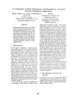
neural network. Fig 1.1 shows the block diagram of the DLPSO algorithm which
is self explanatory.
Fig 1.1: Block Diagram of the DLPSO algorithm
Ø The controller proposed ensures that; at different operating points, the actual
output voltage of the boost converter follows the reference output voltage
efficiently without deteriorating its performance.
Ø The dynamic performance evaluation of the boost converter is carried out by
providing a step change to the reference output voltage and observing the
response of the actual output voltage of the system and thereby, determining the
dynamic performance of the ANN controller. The parameters used for measuring
the dynamic performance of the ANN controller are: a measure of the overshoot
voltage and a measure of the settling time at various operating points.
Ø The performance of the ANN controller designed using the DLPSO algorithm is
benchmarked with a conventional PI controller because the PI controller is the
most commonly used industrial controller due to its ease of implementation and
design.
Ø The performance of the DLPSO algorithm is compared to a generic genetic
algorithm and thus, justifying the implementation of the PSO for this application.
4
1.3
Problem Statement
Designing controllers for non-minimum phase systems is a challenging task and it
is an even more challenging problem when the domain knowledge about the systems is
inadequate. Additionally, while designing controllers for such systems, parameters are
optimized using manual trial and error methods. Also, such systems are operating point
dependant and hence, the controller optimized at one operating point, may not provide
sufficient performance at other operating points.
This thesis deals with the automated design of an ANN controller for such a nonminimum phase systems using the proposed approach which is based on swarm
intelligence, to overcome the above designing difficulties as well as improving the
dynamic performance.
1.4
Structure of the thesis
This thesis is organized into Seven Chapters. The structure and description of the
thesis can be described as follows.
The First Chapter provides a brief introduction, motivation behind the thesis, the
thesis objectives and achievements and organization of the thesis.
Chapter 2 provides the basic background and brief review of the different
artificial intelligence techniques viz., Artificial Neural Network, P article Swarm
Optimization and Genetic Algorithm.
Chapter 3 describes the state of the art review on the different research carried out
in the area for easier understanding of the importance of the proposed contribution.
5
Chapter 4 provides an overview of the boost converter, its control difficulties and
conventional control methods, typically the PI controller for better understanding of the
system to be controlled. In this Chapter the choice of the boost converter as a testing
vehicle and the design difficulties of controller design are also elucidated. The Problem
Statement has been defined in this Chapter.
Chapter 5 presents the basic implementation of the proposed neural network
controller called Duel Layered Particle Swarm Optimization (DLPSO) Algorithm which
has been proposed for mitigating the Problem Statement in the previous chapter. In the
first section, control scheme of ANN, then the configuration of neural network i s
discussed. In the following sections, the mathematical modeling, neural network design,
principal of DLPSO, implementation of DLPSO are detailed. The next sections consists
of basic design configuration of the benchmark PI Controller and weight optimization
using GA and PSO based Hybrid approach are discussed.
Thus, in Chapter 6, detailed Optimization, Simulation Results and Comparisons
are presented. The proposed algorithm is for the design and optimization of both the
configuration and the connection weights. In the first section optimization parameters of
DLPSO is explained and following section describe Simulation Results of DLPSO. Then
the performance of the proposed algorithm is compared to a conventional PI controller
and the advantages explained and finally the proposed approach for the design of the
architecture of the ANN is compared to that of a basic genetic algorithm to prove the
effectiveness of a PSO based algorithm over a genetic algorithm for this application. The
performance is evaluated based on parameters such as computational time and number of
generations.
6
Finally, Chapter 7 concludes this thesis highlighting the major contributions of
this research. A brief future research directive based on this thesis is also included.
7
Chapter 2
Background
This chapter provides the basic background and brief review of the different
artificial intelligence techniques viz., Artificial Neural Networks, Particle Swarm
Optimization Algorithm and Genetic Algorithms.
2.1
Artificial Neural Networks
Artificial neural networks are computational networks which attempt to simulate the
network of biological nerve cells (neurons) in the biological central nervous system. The
human brain is made of millions of individual processing elements that are highly
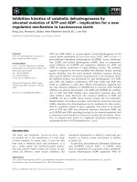
interconnected. A schematic of single biological neuron is shown in figure 2.1.
Fig 2.1: Schematic of a Biological Neuron [8]
Information from the outputs of neurons, in the form of electrical pulses, is received by
the cell at the connections called synapses. This mechanism of signal flow is not via
electrical conduction but rather, attributed to charge exchange transported by the
8