Finite element study of 2d equivalence to 3d analysis of a discrete soil nail problem with applications to serviceability design
Bạn đang xem bản rút gọn của tài liệu. Xem và tải ngay bản đầy đủ của tài liệu tại đây (1.7 MB, 173 trang )
FINITE ELEMENT STUDY OF 2D
EQUIVALENCE TO 3D ANALYSIS OF A
DISCRETE SOIL NAIL PROBLEM WITH
APPLICATIONS TO SERVICEABILITY
DESIGN
by
Lee Cheh Hsien B. Eng (Hons)
A thesis submitted in partial fulfillment of the
requirements for the degree of
Masters of Engineering
National University of Singapore
2003
National University of Singapore
Abstract
FE STUDY OF 2D EQUIVALENCE TO 3D
ANALYSIS OF A DISCRETE SOIL NAIL
PROBLEM WITH APPLICATIONS TO
SERVICEABILITY DESIGN
by
Lee Cheh Hsien
Current trends in design and analysis of soil nailed structures show increasing use of
finite element method (FEM) to verify or predict performance of the system. Due to the need
to do this computationally efficiently, 2D plane strain idealisations of a discretely placed soil
nail have often been used. There are many methods used in the idealisation of a soil nail
problem. However there is lack of current consensus on which method best represents the
problem and also the limitations of each method.
The author has classified these methods broadly into three categories. This thesis seeks
through a comparison of 2D analysis using each method with 3D analysis in FE of the soil nail
problem to clarify the limitations of each method with recommendations to the limitations and
use of each. This is done with both a single row nail comparison as well as a multiple row nail
comparison with 3D FE observations as well as behaviour from an instrumented model soil
nail experiment.
Subsequently, the author attempts to quantify the limitations of 2D analysis by
introducing design limits to the use of 2D analysis. It has been observed that the level of
mobilization of pullout capacity is also different in 2D and 3D. A method of idealisation
utilizing the mobilization factors was also introduced to account for this difference in order to
improve 2D simulation of a 3D problem. In addition, intuitively, the influence of the nail
decreases with spacing between nails. A numerical pullout simulation is done to investigate this
effect and recommendations in the form of a design chart is suggested as a guideline to the
design of spacing and also the recommended use of plane strain analysis. The results from the
nail spacing design chart was then verified with a parametric analysis from a single row soil nail
case with results in good agreement with conclusions from the design chart.
Keywords: finite element methods, 2D/3D comparison, plane strain idealization, soil
nailing, design guidelines
TABLE OF CONTENTS
Table of Contents ................................................................................................................i
List of Figures.................................................................................................................... iv
List of Tables .................................................................................................................... vii
Acknowledgments ........................................................................................................... viii
Nomenclature .................................................................................................................... ix
Chapter 1 ............................................................................................................................. 2
Introduction........................................................................................................................ 2
1.1 Introduction to Soil Nailing...................................................................................................2
1.1.1 Description of Soil Nailing Technique................................................................................. 3
1.1.2 Mechanism of Soil Nailing Behaviour in Reinforcement of Soil Structure ............................ 4
1.1.3 Advantages and Disadvantages of Soil Nailing as a Geotechnical Application ................... 7
1.1.4 Development of Soil Nail Applications with Time .............................................................. 8
1.2 Use of FE Analysis as a Design and Analysis Tool in Soil Nailing ..............................11
1.2.1 Current Issues Regarding Use of FEM in Soil Nailing and Scope of Proposed Research ..12
Chapter 2............................................................................................................................15
Literature Review ..............................................................................................................15
2.1 Current Methods of Analysis for Soil Nailing ..................................................................15
2.1.1 Limit Equilibrium Methods (LEM)................................................................................16
2.1.2 Comparisons with Finite Element Methods (FEM) .........................................................21
2.2 Comparison of 3D modelling and Proposed Methods of 2D Idealisation ................24
2.2.1 Idealisation Method A: Using a Composite Material to combine the soil and reinforcement
into one material ..............................................................................................................................25
2.2.2 Idealisation Method B: Plane Strain Assumption by simulating discrete reinforcements with a
continuous plate ...............................................................................................................................27
2.2.3 Idealisation Method C: Simulation of Nail as an external body connected to a continuous soil
using connector elements....................................................................................................................29
2.2.4 Summary of Comparison of Methods.................................................................................31
Chapter 3........................................................................................................................... 34
Objective and Scope of Research .................................................................................... 34
3.1 Objective..................................................................................................................................34
3.2 Methodology and Scope of Research.................................................................................35
Chapter 4........................................................................................................................... 38
2-d Idealisation of Discrete Nail: Effect of Smearing of discrete nail as a continuous
plate................................................................................................................................... 38
4.1 Definition of Smearing in 2D Idealisation ........................................................................38
4.2 Scheme of Smearing of a Single Row Soil Nail System..................................................39
4.2.1 Smearing of Nail Properties ..............................................................................................39
4.2.2 Smearing of Interfacial Properties.......................................................................................40
4.2.3 Smearing of Interface Rigidity ............................................................................................42
4.3 Effect of Smearing of Interface Properties.......................................................................43
4.3.1 Influence of Area Factor, Af..............................................................................................43
4.3.2 Influence of Interaction Factors, Io and I1 ...........................................................................44
4.4
Recommendations for interfacial parameters used in 3D analysis and 2D Idealisation
48
Chapter 5........................................................................................................................... 52
2-d Idealisation of Discrete Nail: Comparison of Different Methods with a single row
soil nail system.................................................................................................................. 52
5.1 Introduction to 2D Idealisation of a Discrete Reinforcement......................................52
5.2 Different Idealisations of a Single Row Soil Nail System...............................................53
5.2.1 Definition of a Single Row Soil Nail Set Up ....................................................................53
5.2.2 Scheme of 2D Idealisations of Single Nail Problem:: Method A .......................................55
5.2.3 Scheme of 2D Idealisations of Single Nail Problem: Method B and C..............................57
5.3 Comparisons of Different 2D Idealisations of Single Nail Problem ...........................59
5.3.1 Comparison of Computational Requirements and Modeling Efficiency ..............................59
5.3.2 Deformation Behaviour of Facing due to Effect of Idealisation...........................................60
5.3.3 Force Mobilisation in Nails due to Effect of Idealisation ...................................................63
5.3.4 Stress Mobilisation in Soil due to Effect of Idealisation .....................................................66
5.3.5 Modes of Failure ...............................................................................................................71
5.4 Preliminary Conclusions .......................................................................................................73
5.4.1 Advantages and Disadvantages of 2D Idealisation............................................................73
5.4.2 Comparisons of Different Methods of 2D Idealisation.......................................................73
5.4.3 Aspects of behaviour accounting for difference in behaviour due to 2D Idealisation.............74
Chapter 6........................................................................................................................... 77
2-d Idealisation of Discrete Nail: Comparison of Different Methods with a Multiple
row soil nail system .......................................................................................................... 77
6.1 2D Idealisation of a full scale Soil Nail System ................................................................77
6.2 Numerical Model of a Multiple Row Soil Nail System...................................................78
6.2.1 Multiple Soil Nail System: Test Setup..............................................................................78
6.2.2 Multiple Soil Nail System: 3D model and 2D idealisations using Method B and C ........80
6.3 Comparisons of Different 2D Idealisations of Preburied Nails System .....................83
6.3.1 Comparison of Computational Requirements and Modeling Efficiency ..............................83
6.3.2 Deformation Behaviour of Facing due to Effect of Idealisation...........................................84
6.3.3 Force Mobilisation in Nails due to Effect of Idealisation ...................................................85
6.3.4 Stress Mobilisation in Soil due to Effect of Idealisation .....................................................94
6.4 Verification of 2D FE Recommendations with Soil Nail Experiment Results .........96
6.5 Comparison of FE Behaviour and Experimental Behaviour ........................................97
6.6 Conclusions and Recommendations ................................................................................100
6.6.1 Conclusions and Recommendations from 2D/3D Comparison .......................................100
6.6.2 Conclusions and Recommendations from Verification 2D FE Analysis with Experimental
Test Results ...................................................................................................................................101
Chapter 7..........................................................................................................................104
Numerical Pullout Simulation to Verify Nail-Soil-Nail Interaction .............................104
7.1 Effect of Nail Spacing to Nail-Soil-Nail Interaction.....................................................104
7.2 Reinforcing Effect Multiple Nail-Soil Interaction: Effect of Mutual Reinforcement
106
7.3 Results From Numerical Model of a Single Nail Pullout Test....................................108
7.4 Results From Numerical Model of a Single Nail Pullout Test....................................112
ii
7.5 Recommended Spacing Design Based on Influence Zone and Comparisons with
Current Recommendations and Practice for Spacing...............................................................113
Chapter 8.......................................................................................................................... 116
Parametric Study of Different Influence Factors on Soil Nail Behaviour..................... 116
8.1 Introduction to Objectives of Parametric Analysis .......................................................116
8.2 Scheme of Parametric Analysis .........................................................................................117
8.3 Discussion of Results From Parametric Analysis ..........................................................118
8.3.1 Comparison of Behaviour with Variation of Relative Stiffness Parameter, N..................118
8.3.2 Comparison of Behaviour with Variation of Nail Spacing, Sh ........................................121
8.3.3 Comparison of Behaviour with Variation by Soil Stiffness, Es ........................................123
8.4 Conclusions of Parametric Analysis .................................................................................125
Chapter 9..........................................................................................................................129
General Conclusions and Recommendations ................................................................129
9.1 Summary of Work According to Objective and Scope ................................................129
9.2 General Conclusions ...........................................................................................................130
9.2.1 Interaction Factors to Idealisation....................................................................................130
9.2.2 Comparison of Various Methods ....................................................................................130
9.2.3 Nail-Soil-Nail Interaction ..............................................................................................132
9.3 Recommendations For Future Work...............................................................................133
9.3.1 Implementation of Method C...........................................................................................134
9.3.2 Further Development and Verification of FE Design Charts with Actual Field Application
135
9.3.3 Soil models incorporating dilative behaviour .....................................................................135
References........................................................................................................................138
Appendixes ......................................................................................................................A-1
Appendix A.
Case histories of 2D Idealisation of FE Problems Related with Ground
Improvement and Soil Nailing ..................................................................................................... A-1
Appendix B.
Effect of Restrained Dilatancy In Actual Soil Nail Behaviour.................B-1
Appendix C.
Deflection and Forces for Output of Multiple Row Soil Nail System ...C-1
Appendix D.
Soil Nail Parameters of Previous Case Studies...........................................D-1
iii
LIST OF FIGURES
Figure Number
Page
Figure 1.1. Stages in Construction of Soil Nail Wall.............................................................................. 4
Figure 1.2. Comparisons of Lateral Displacements Between a Soil Nailed Wall and a Reinforced
Earth Wall ...................................................................................................................................... 4
Figure 1.3. Nail-Soil Interactive behaviour mobilizing tensile, bending and shearing forces in the
nail.................................................................................................................................................... 6
Figure 1.4. Modes of failure encountered by soil nailing ...................................................................... 7
Figure 1.5. Development of applications for soil nailing from tunnel construction to slope
stabilization ..................................................................................................................................10
Figure 2.1. The German Method of assuming bilinear failure surface (Stocker et al., 1979) .......18
Figure 2.2. The Shen Method using parabolic failure surface (Shen et al., 1978)...........................18
Figure 2.3. The Juran Method using log-spiral failure surface (Juran et al., 1990) .........................19
Figure 2.4. Multicriteria Approach and Final Yield Theory by Schlosser........................................19
Figure 2.5. Jewell’s design charts for serviceability for a reinforced soil wall by reinforcements 21
Figure 2.6. Homogenised representation of reinforced soil mass in a soil nail structure (de
Buhan and Salençon, 1987).......................................................................................................26
Figure 2.7. Representation of nail as a smeared plane strain idealized plate....................................30
Figure 2.8. Details of finite element mesh at facing-reinforcement connections...........................31
Figure 2.9. Comparison of Usage of Methods for 2D Idealisation ..................................................31
Figure 3.1. Scheme of methodology of research ..................................................................................36
Figure 4.1. Schematic showing smearing of a discrete nail into a continuous plate ......................41
Figure 4.2. Under predictions of pullout capacity in 3D numerical pullout from expected values
........................................................................................................................................................43
Figure 4.3. Stresses in soil around the nail due to soil movement during pullout..........................45
Figure 4.4. Variation of (a) Io with Average overburden pressure, (b) Io with relative stiffness of
nail to soil for different nail spacing........................................................................................46
Figure 4.5. Effect of Influence factors on accuracy of deflection in 2D of 3D facing behaviour
for a single row soil nail system................................................................................................47
Figure 5.1. Mesh in 3D modelling of single soil nail............................................................................54
Figure 5.2. Mesh Representation of Idealisation using Method A with deformation at various w
........................................................................................................................................................56
Figure 5.3. 2D plane strain analysis FE mesh showing different schemes of idealisation Method
B and Method C..........................................................................................................................58
Figure 5.4. Comparisons of deflection of facing for different 2D models with 3D behaviour (a)
excavation depth 1m. (b) excavation depth 1.3m. and (c) excavation depth 1.65m. .....62
Figure 5.5. Forces Mobilised in Nail (a) excavation depth 1m. (b) excavation depth 1.3m. and (c)
excavation depth 1.65m.............................................................................................................64
Figure 5.6. Moments Mobilised in Nail (a) excavation depth 1m. (b) excavation depth 1.3m. and
(c) excavation depth 1.65m. ......................................................................................................65
iv
Figure 5.7. Shear stresses developed in a cut out section at the midspan of (a) 3D discrete nail
deformed mesh, (b) 2D cross section extruded idealised plate in Method B and (c) 2D
cross section extruded idealised plate in Method C .............................................................67
Figure 5.8. Comparisons of Contact shear stress and Contact pressure mobilisation along top
and bottom interfaces for Method B and Method C Idealisations with 3D Model. .....68
Figure 5.9. Mobilisation Factors of Shear of a single row soil nail problem at 1m spacing .........69
Figure 5.10. (a) Mobilised pressures and (b) shear mobilisation in 3D exceeding calculated
overburden pressures and expected contact shear resulting in higher than expected
pullout strength for soil of Es = 5910kPa ..............................................................................69
Figure 5.11. Values of Interaction factor I1 over a range of relative nail-soil stiffness..................70
Figure 5.12. Comparison of Plastic Equivalent Strains at Integration Points for Methods B and
C and 3D simulation at excavation depth 1.65m (scales are the same for all figures)...72
Figure 6.1. Photograph showing trench test experimental set up (Raju, 1996) ..............................78
Figure 6.2. Schematic sketch of test set up (Raju, 1996) .....................................................................79
Figure 6.3. Schematic of 3D mesh for multiple row soil nail model ................................................81
Figure 6.4. Schematic of 2D mesh for multiple row soil nail model using Method B and Method
C Idealisation ...............................................................................................................................81
Figure 6.5. Comparisons of deformation over excavation height ratio for preburied and installed
schemes at various excavation stages......................................................................................85
Figure 6.6. Preburied soil nail system behaviour at various stages of excavations with
comparisons in deflections of facing, axial nail force distribution and maxima .............89
Figure 6.7. Installed soil nail system behaviour at various stages of excavations with
comparisons in deflections of facing, axial nail force distribution and maxima .............91
Figure 6.8. Schematic showing typical shear stress in soil during excavation for a 3D model and
resultant nail forces as well as locus of maximum tensile nail force .................................92
Figure 6.9. Soil Strain just prior to calculation failure for installation scheme compared against
locus of points of zero moment of moments mobilised in nails for Method C
idealisation and 3D model. (Note: Method B not shown because of early failure at
previous stage).............................................................................................................................92
Figure 6.10. Comparison of Shear stresses and movements for (a) 3D model and 2D
idealisations (b) Method B and (c) Method C for preburied scheme at excavation stage
4......................................................................................................................................................95
Figure 6.11. Comparison of Model Test Behaviour and FE Simulation using proposed methd of
smearing incorporating interaction factors and continuous soil model .........................100
Figure 7.1. Comparison for variation of nail spacing (a) Force at mid-span of nail, (b) Moments
at mid span of nail, (c) Deflection at nail height.................................................................106
Figure 7.2. Schematic showing common assumptions on loading area of nail and postulated
influence area of 3d- nail .........................................................................................................107
Figure 7.3. Mesh for Pullout Parametric Analysis to find Influence Zone of Nail......................109
Figure 7.4. Soil (a) Deviatoric Stress Changes and (b) Shear Stresses in between adjacent nails at
0.25m spacing and 1m spacing...............................................................................................111
Figure 7.5. Soil Shear Development with Increase in Relative Stiffness of Nail over Soil.........112
Figure 7.6. Design Chart from Parametric analysis of Pullout of Single Nail to find Influence
Radius Ratio, Ri/L by varying slenderness ratio, x/L of nail with case histories .........114
Figure 8.1. Parametric Analysis with Variation of Spacing (a) Deflection Ratio at Nail Height of
Facing, (b) Force at midspan of nail, at different relative stiffness parameter, N ........120
v
Figure 8.2. Comparison of differences in differences in deformations at nail height for 2D and
3D at different relative stiffness for different spacing to influence radius ratio ...........121
Figure 8.3. Margin of Error for Various Elasticity of Soil (Es/kPa) for Percentage of Error in
Deflection of Facing at Nail Height......................................................................................123
Figure 8.4. Parametric Analysis with Variation of Soil Elasticity, Es ..............................................125
Figure B.1 Increased confining pressure due to effect of restrained dilatancy (Plumelle) ....B-1
Figure B.2 3D nature of restrained dilatancy occurring at edges of reinforcement as
compared to free dilatancy at middle of strip reinforcement (Hayashi, Alfaro,
Watanabe) and comparison with shear developedduring full pullout in pullout
numerical model........................................................................................................................B-2
Figure C.1 Deflection for Preburied Scheme at various excavation stages..............................C-1
Figure C.2 (a) Axial Forces and (b) Bending Moments along nail length (m) for Nail 1 at
various excavation stages.........................................................................................................C-2
Figure C.3
(a)Axial Forces and (b) Bending Moments along nail length (m) for Nail 2 at
various excavation stages.........................................................................................................C-3
Figure C.4 (a)Axial Forces and (b) Bending Moments along nail length (m) for Nail 3 at
various excavation stages.........................................................................................................C-4
Figure C.5 (a) Axial Forces and (b) Bending Moments along nail length (m) for Nail 4 at
various excavation stages............................................................................................................. 5
Figure C.6 (a)Axial Forces and (b) Bending Moments along nail length (m) for Nail 5 at
various excavation stages............................................................................................................. 5
Figure C.7 Deflection for Preburied Scheme at various excavation stages..............................C-4
Figure C.8 (a) Axial Forces and (b) Bending Moments along nail length (m) for Nail 1 at
various excavation stages.........................................................................................................C-5
Figure C.9 (a)Axial Forces and (b) Bending Moments along nail length (m) for Nail 2 at
various excavation stages.........................................................................................................C-6
Figure C.10
(a)Axial Forces and (b) Bending Moments along nail length (m) for Nail 3 at
various excavation stages............................................................................................................. 7
Figure C.11
(a)Axial Forces and (b) Bending Moments along nail length (m) for Nail 5 at
various excavation stages............................................................................................................. 7
vi
LIST OF TABLES
Table Number
Page
Table 4.1
Characteristics of Smearing in 2D Idealisation............................................................38
Table 5.1
Summary of Scheme of Idealisation ..............................................................................53
Table 5.2
Parameters used for Method A Idealisation Model for Single Nail Excavation
Problem ........................................................................................................................................56
Table 5.3
Parameters used in FEM model in 2D and 3D for nail at 1m spacing...................58
Table 5.4
Summary of Comparisons of Computational Capability of Idealisation................60
Table 6.1
Parameters used in FEM model in 2D and 3D for nail at 1m spacing...................82
Table 6.2
Summary of Stages of Analysis.......................................................................................82
Table 6.3
Comparison of Computational Capability of Idealised Meshes with 3D Mesh....83
Table 6.4
Comparison of Error in Deformations from 3D due to Idealisation at Stages 3, 4
and 5..............................................................................................................................................84
Table 6.5
Comparison of Mean Squared Error in Maximum Tensile Nail Forces from 3D
due to Idealisation.......................................................................................................................86
Table 6.6
Parameters used in FEM model in comparison with experiment ...........................96
Table 8.1
Parametric Variation in FEM model in 2D and 3D for nail...................................118
Table 8.2
Summary of Conclusions From Parametric Analysis...............................................127
vii
ACKNOWLEDGMENTS
In the process of completing this thesis, I experienced many moments of trials and
triumphs. It is not the end result that matters the most, but each person that has made reaching
it not only possible, but also the process memorable. For that, I wish to acknowledge the
following people:
Ms. Kendice Chan, my fiancé, best friend and constant encouragement to me. Your
smile is better than the sunshine, and always magical to me.
My family, who has provided me a place to grow up, learn about life and pursue my
dreams. You will always be an inspiration for me to do so the rest of my life.
My friends at NUS from all over the world (China, Bangladesh, India, Myanmar,
Indonesia, Germany, Thailand and Malaysia), gathered together here. I thank God for the
privilege of knowing you, working with you and learning from you. Sometimes I feel like the
minority in the midst of you, and have become richer as a result of it.
My supervisors, A/Prof Tan Siew Ann, and Dr Ganeswara Rao Dasari. You have
added so much more to each page of this thesis just by your combined experience and advice. I
am truly blessed to have you guide me through each step of the way.
And last and most importantly, Jesus Christ , my Lord and Saviour. No words will ever
be enough to thank You for what You have done, and still continue to do each day of my life.
All glory belongs to You alone. Amen.
viii
NOMENCLATURE
Es, Eplate, En (kPa)
Young’s modulus of soil, 2D idealized plate and 3D nail
Āplate, Ānail (m2)
Aplate, Anail (m2)
Ān
Cross sectional area of 2D idealized plate and 3D nail
Contact surface area of 2D idealized plate and 3D nail with soil
Cross sectional area factor
Af
µ
µ2d
Contact surface area factor
Coefficient of friction in 3D nail-soil interface
Reduced coefficient of friction in 2D nail-soil interface by area factor
method
Reduced coefficient of friction in 2D nail-soil interface by area factor
+ interaction factors method
µR
F2D,F3D (kN)
Mobilised shear force at the nail-soil interface in 2D and 3D analysis
Punif, P2D, P3D (kN)
Pullout capacity at the nail-soil interface with uniform normal
pressures and in FE 2D and 3D analysis
Average calculated overburden pressure at nail height
σav (kPa)
σfacing (kPa)
Io, I1
M2D, M3d
Average calculated horizontal pressure on facing over excavation
depth
Interaction factors accounting for reduced pullout force and
differences in mobilization
Mobilisation factors of 2D plate and 3D nail forces at interface of
respective pullout capacities
K2D, K3D (kPa)
Shear rigidity at nail-soil interface for 2D idealized plate and 3D nail
τ2D, τ3d(kPa)
Shear forces at nail-soil interface for 2D idealized plate and 3D nail
γ2D, γ3d
Shear strain at nail soil interface for 2D idealized plate and 3D nail
γcrit
Slip tolerance parameter for ABAQUS input for nail-soil interface
δ (m)
Deflection at nail height
H (m)
Height of excavation
x, L (m)
Width and length of 3D nail
Sv, Sh (m)
Vertical and horizontal spacing of nail
Ka, Ko
Active and at rest horizontal coefficient of pressure
N
Ratio of relative axial rigidity of nail to soil
ix
1
Chapter 1
INTRODUCTION
1.1
Introduction to Soil Nailing
The technology of ground reinforcement has been familiar to mankind throughout
civilisation. Ingenious techniques have been known to be applied to ancient structures as far
back as 2100 B.C. in the construction of ziggurats and other monuments (Kerisel, 1987) which
involve layering of materials bearing tensile strength interbedded with compressive materials
like soil and gravel to form a reinforced composite. Even though the technique of reinforcing
the ground with other materials providing additional strength is known and practised, it is in
1966 when Vidal introduced the method of reinforced earth that the technology of ground
reinforcement became a much studied and well-used technique. Since then many other types of
ground improvement and reinforcing techniques have arose, including that of soil nailing.
Ground reinforcement techniques may be classified broadly into two main categories
(Schlosser and Juran, 1979):
•
In-situ soil reinforcement
•
Remoulded soil reinforcement
The reinforced earth technique abovementioned follows the second method where the
soil is built up together with the reinforcement, which may comprise of geogrids, geotextiles or
steel strips. However, since many geotechnical applications require reinforcement that needs to
be placed insitu, such as excavated walls or slopes, rather than built up structures, such as
embankments, the former category has been developed in recent times to be an important
aspect of ground reinforcement. Such techniques like soil nailing and dowelling, have received
tremendous development over the last 25 years.
2
1.1.1
Description of Soil Nailing Technique
Soil nailing is a method of slope stabilization or ground improvement that involves the
use of passive inclusions; usually steel bars (known as soil nails), to reinforce insitu retained
ground. Its installation is progressive and is carried out simultaneously with soil excavation in
front of the retained wall. This takes place in a series of successive phases as shown in Figure
1.1. They are usually in the following order:
•
Excavation of about 1-2m of soil. This is dependent on soil type. If excessive depth
of soil is excavated, the soil is subject to failure locally.
•
The introduction of nails, at horizontal or inclined angles, is done by a variety of
methods including jacking, driving or boring and grouting.
•
Building a facing in connection to the nails. This has been traditionally done with
shotcrete but hybrid nail-walls involving stiffer walls or precast facing elements has
been used recently.
The sequence is then repeated until the required depth of excavation. The
reinforcement principle of the soil nailing method may seem to resemble that of the reinforced
earth method. However due to the method of installation, the soil nailing method produces a
very different behaviour from that of reinforced earth which is generally marked by the point
of maximum displacement. Soil nailing produces greater displacements at the top of the
excavation while reinforced earth show larger displacements near the bottom (Figure 1.2). This
shows that the method of installation has a great impact on the mobilization of forces within
the system and should be properly understood with the properties and geometry of the
materials involved to gain an understanding of the overall behaviour of the system.
3
Steps are
repeated
until
required
depth
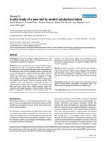
Figure 1.1. Stages in Construction of Soil Nail Wall
Figure 1.2. Comparisons of Lateral Displacements Between a Soil Nailed Wall and a Reinforced
Earth Wall
1.1.2
Mechanism of Soil Nailing Behaviour in Reinforcement of Soil Structure
The purest form of soil nailing, without the use of any pretension or preloading and
connected with a weak facing, acts in response to the deformation of the system. This is
because the nails are placed as passive inclusions and offers no support to the system when
initially installed. However, with excavation of the soil in front of the retained soil, the soil
4
moves in active response to the unloading and undergoes deformation. The deformation of the
soil transfers the loading to the nails.
Two possible types of interaction are developed. The primary action is the interaction
of shear stress along the nail-soil interface, which is subsequently transferred into the nail as
tensile forces. The secondary action, which have been much debated over in the 1990s are the
action of shear and bending, which is developed as a result of passive pressure of the earth
along the nail. This is observable when shear zones in the soil develop to form active and
passive zones. Jewell (1990) proposed that this effect is only critical when the nail is
approaching failure (Figure 1.3).
When loading of the system takes place, the soil nailed wall may approach failure
mainly by either breakage due to insufficient structural capacity of the nail, pullout of nail due
to lack of adherence at the nail-soil interface, or global instability of the retained slope or
structure (external failure). There may be other forms of failure locally due to excessive
excavation depth prior to installation of subsequent nail or piping of soil (internal failure)
(CLOUTERRE, 1990). In general, they may be summarized into four forms:
•
Instability during excavation phases, Figure 1.4 (a), (b) and (c)
•
Overall sliding of the reinforced mass, Figure 1.4 (a), (b) and (c)
•
Lack of Friction between soil and nails, Figure 1.4 (d)
•
Breakage of the nails, Figure 1.4 (e)
Based on these failure modes, design may be made using limit equilibrium methods to
find out safety against different modes of failure. However, the behaviour of soil nails is also
subject to the many variations in design specifications of geometry and layout, coupled with the
variation of site and materials used make for a very complicated design process.
5
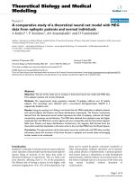
(a) Pullout test behaviour modelling by Frank and Zhao’s
Law showing shear mobilisation at the nail-soil interface
due relative slip from tensile pullout force
Shear
Zones
Analogous
nail
(b) Bending and shear force mobilisation in the nail due to
passive reaction of soil on nail due to relative movements
of shear zones
Figure 1.3. Nail-Soil Interactive behaviour mobilizing tensile, bending and shearing forces in the
nail
6
(a) Internal Failure
(d) Failure by lack of adherrance at nail-soil
interface (Eparris wall)
(b) External Failure
(e) Failure by breakage of nails (CEBTP 1,
Clouterre)
Figure 1.4. Modes of failure encountered by soil nailing
(c) Combination of Internal and External Failure
1.1.3
Advantages and Disadvantages of Soil Nailing as a Geotechnical Application
The main advantages of soil nailing are its cost saving features of both time and effort
as well as its adaptability to site conditions. The construction of a soil nailed wall does not
require a lot of heavy machinery and may be completed efficiently and quickly because it is
conducted at the excavation level. Hence, it does not hamper construction progress.
Soil nailing is readily adaptable, and changes can be made to its design readily even in
the midst of construction. Segmented construction may also be done with no restriction to
7
curved geometry of the reinforced slope or wall. Minor changes in the presence of local
obstruction such as boulders also make it a very adaptable design since local adjustments may
not affect the overall design performance very much.
Comparing with other methods that may be applicable, soil nails are also more cost
efficient because it combines speed, simplicity and the use of light equipment.
However, soil nailing also suffers certain drawbacks in that movements are inherent to
the problem. This is because soil nails are passive in nature and require movements of the soil
to mobilize forces in reaction to provide stabilizing action to the reinforced portion. It is also
hard to construct soil nailed walls in ground with a high water table, or soils which are
cohesionless (e.g. pure sands).
In addition, the durability of the soil nail is important for permanent structures.
Corrosive soils against bare driven steel nails with little or no protection only allow soil
reinforcement in the short-term conditions.
1.1.4
Development of Soil Nail Applications with Time
Besides the need for insitu ground reinforcement in existing ground, the growth in
popularity of use of soil nails is due to advantages in its ease of installation as well as cost
effectiveness. Bruce and Jewell (1987) describes soil nailing to have been developed from
tunnelling techniques, where rock bolts are used in mining methods and construction of
tunnels by the New Austrian Tunnelling Method (Figure 1.5) during the 1960s for ground
improvement during excavation. The principles were then subsequently developed for slope
stabilization application into the present form of soil nailing. Many of the various soil nailing
techniques were developed in the second half of the seventies and are still being used with
great success (Gassler, 1990).
8
CLOUTERRE 1991 details the landmark developments for soil nail research and
development have progressed as follows:
•
First wall built at Versailles in 1972/1973 by contractors Bouygues and Soletanche,
involving wall built in Fountainbleau sand, using a high dense mesh of closely spaced
short nails anchored with grout
•
First full-scale experiment in Germany (Stocker et al., 1979) using grouted nails and
loaded to failure by surcharge in 1979.
•
First attempt in “industrialization” with prefabrication of facing units in France in
1981. (Louis, 1981)
•
National research project for soil nailing (CLOUTERRE, 1991)
Since the initiation of soil nailing methods, researchers in Germany have also begun a
research and development project “Bodenvernagelung” in 1975, with a simultaneous and
independent development in USA known as “Lateral Earth Support System”. Many others
have also begun forms of research in the field of soil nailing either in the documentation of
field performance analysis by limit equilibrium methods or FEM, design of soil nails or
investigation of behaviour of soil nail interaction with laboratory or field studies.
Initially soil nails were used mainly as temporary slope stabilizers. This stemmed from
the fact that the first nails used were driven short steel angles via method “Hurpinoise”, as
such, they were subject to much corrosion. However, with new advances in nail protection and
the use of grouted nails, the longevity of the nails was prolonged and its use has been widely
accepted in the long term. Since then, other methods which seek to improve the installation
process as well as the long term performance of the soil nails have been introduced, like the jet
grouted nail (Louis, 1984) where the grout is introduced at the tip of the nail. The grout serves
as lubrication during the process of installation while the nail is driven in by the percussion
9
method. Other methods have included installation by ballistic methods (Ingold and Myles,
1996). Other materials such as glass fibre rods have been researched on, however the extensive
use of these alternative materials have been much slower.
(a) Traditional methods of tunnelling and
soil nailing used in Austrian tunneling
method for lining a gallery
(b) Soil nailing used as a soil stanbilisation
application at Versailles (Rabejac and
Toudic, 1974)
Figure 1.5. Development of applications for soil nailing from tunnel construction to slope
stabilization
With these improvements, the application of soil nailing has been extended to include
permanent reinforced structures with even applications in remedial work (Schwing and
Gudehas, 1998). For this purpose, the performance of soil nails to control wall displacement
under service conditions becomes important. If a strict condition for serviceability is imposed,
there is a greater need to understand the deformation performance of the soil nail system at the
design stage. This is especially so when the deformation condition is more restrictive than the
ultimate condition.
To date, soil nail design has been based mainly on stability considerations arising
mainly over the past few decades. There have only been a few design criteria in the
consideration of deformation of a soil nailed wall published. There has been much study of the
10
soil nail behaviour near failure where limit equilibrium methods make use of assumptions of
interaction between nail and soil at failure conditions. However usually the retaining system at
service loads is not near failure and failure condition assumptions may be quite different from
actual mobilized forces in the nail. This coupled with the many possible variations of design
parameters, interaction between different elements of the soil nail system like facing, nail and
soil and the process of installation makes it even more difficult to arrive at a satisfactory design
criteria for serviceability. Hence computerized numerical methods like finite element models
(FEM), which are able to model structural interaction between different elements as well as
material changes with deformation becomes an attractive option to predict actual behaviour
and serve as a design and analysis tool for soil nailing.
1.2
Use of FE Analysis as a Design and Analysis Tool in Soil Nailing
Finite element method has been used in research over the past thirty years for various
fields of engineering. However, it is within the last twenty years especially that geotechnical
applications have been widely used. Many complicated issues accompany use of the finite
element model to simulate actual behaviour. However, its applications offer many advantages
to the study in the field of geotechnical structures.
In the field of reinforced earth and soil nailing, FEM was used initially to back analyse
laboratory or field performances of soil nailed structures (Chaoui, 1982; Fernandes, 1986;
Unterreiner et. al, 1987; Benhamida et. al, 1997). It is important to understand the behaviour of
soil nail structures, the interaction between the various elements of a soil nail system as well as
verification of parameters used in design. One critical aspect of soil nail behaviour is that it is a
passive inclusion. This implies that the mobilisation of its resistance is dependant on its
interaction with the surrounding elements. FEM provides a great advantage over Limit
Equilibrium Methods (LEM), because it is able to simulate interaction between the nail and its
11
surrounding soil. Another major superiority of FEM over LEM is that it is able to simulate
construction and installation processes. LEM is only able to simulate conditions at failure, and
often requires assumptions on modes of failure. As shown earlier, the failure mechanisms of
soil nailing are varied and complex and assumptions on modes of failure need to be
comprehensive in order to discover most critical cases.
FEM also serves as a tool to verify design assumptions and viability. Due to the
cheaper cost of constructing a numerical model as compared to a laboratory test or even a field
prototype, it provides a useful check whether the performance of the wall will lie within
serviceability and structural limits.
1.2.1
Current Issues Regarding Use of FEM in Soil Nailing and Scope of Proposed Research
The use of FEM is also subject to many pitfalls. The soil nail being discretely placed is
in essence a problem in 3D. However a simple problem in 3D can amount to ten times the
computational requirement as compared to a 2D plane strain analysis. Computational cost in
terms of time and hardware requirement prevents 3D simulation of the soil nail problem from
being widely used. However due to the repeated nature of the positioning of soil nails, FE
users have often idealised the soil nail problem in 2D plane strain analysis as early as 1978 (AlHussaini et. al, 1978; Naylor, 1978). However, this introduces additional considerations in such
FE analysis from the viewpoint of accuracy of the simulation. The soil nail, being simulated as
a smeared material, and idealised as a plate creates discontinuities in the soil. This affects
mobilisation of stresses, and overall behaviour. FE users have attempted various types of
idealisation without a consensus or comparison of methods. This results in a lot of confusion
and misunderstanding of 2D analysis of the soil nail problem.
The use of accurate constitutive models to represent actual material is sometimes
critical to an accurate and acceptable prediction of behaviour. Further inaccuracies of
12
parameters used due to error in soil sampling, non-applicability of tests contribute to further
error. In the face of so many possible origins of error involved, it is difficult to ascertain the
accuracy of FE analysis of a 2D idealisation analysis. It would be a vast improvement to the
quality of the FE analysis done if the errors to 2D idealisation from 3D behaviour could be
minimised.
The author hope that this thesis will address some of the problems involved in the 2D
idealisation of the soil nail problem and hence maximise the user’s understanding of the finite
element method in geotechnical design of soil nail structures.
13