Đồ án kết cấu nhà thép nhà dân dụng
Bạn đang xem bản rút gọn của tài liệu. Xem và tải ngay bản đầy đủ của tài liệu tại đây (1.51 MB, 36 trang )
Project: Structural Steel Design
Instructor: Ms.c Viet Hieu Pham
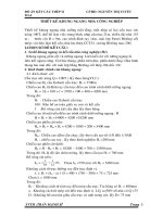
A) DATA
I.> Initial Data
Spans L1 =
10 (m)
L2 =
4.6 (m)
- Column spacing
B1 =:
6 (m)
B2 =
6 (m)
- Hight of floor: Ht =
3.3 (m)
- Design frame: Frame 4th
- Minh Hóa - Quảng Bình -> Zone of wind I A -> W0 =
65 (daN/m2)
- Wall be built by perforated, thickness 100 mm put on exterior beam of construction :
"Ƴ1 = 180 (daN/m2)
- Assume the Gypsum partition tile put on beam:
35 (daN/m2)
"Ƴ2 =
- Live load of office: pc =
2 (kN/m2)
- Live Load of corridor
: pc = 3 (kN/m2)
- Live Roof :
pc =
0.75 (kN/m2)
- Concrete Roof-Slab have sealing and insulation coat .
- Grade of steel: CCT34 -> f = 21 (daN/mm2)
- Type of Welding stick: N42
- Grade of bolt 5.8
B) CACULATING AND PROCESSING OF DATA
I.> Determine the beam gird:
- Design frame 4th -> We have the plan of construction Fig I.1 :
Fig I.1 : The Plan construction and Beam gird system
II.> Determine the thickness, self-weight of slab and loading.
- Dimension of slab 2x6 (m)
- The thickness of slab be detemined follow fomular:
h=
×
≥ℎ
= 5(
)
1.4
× 2 = 0.07
= 7(
40
Choose:Thickness of slab 8 (cm) =
⇔ h=
Student: Thanh Nguyen Ngo - 172216544
)≥ℎ
= 5(
)
80 (mm)
Page:..
Project: Structural Steel Design
Instructor: Ms.c Viet Hieu Pham
- Determine the Dead Load of slab:
Table II.1 Dead Load of Slab
Load
Types of loading
No.
(daN/m2)
Layer of ceramic tile, t = 8
16
1
mm
Layer of mortar, t = 15 mm
30
2
2000x0.015
3
The concrete slab, t = 80 mm
2500x0.08
The concrete slab, t = 80 mm
2500x0.08
Factored Load
(daN/m2)
1.1
17.6
1.3
39
1.1
228.8
-> gs
285.4
(daN/m2)
Factor of
Safety n
Factored Load
(daN/m2)
1.3
52
1.3
26
1.1
228.8
-> gs
306.8
(daN/m2)
208
- Determine the Dead Load of roof slab:
Table II.2 Dead Load of Slab
Load
Types of loading
No.
(daN/m2)
Layer of the sealing, t =20
mm
40
1
2000x0.02
Layer of the insulation 10
20
2
mm
3
Factor of
Safety n
208
III.> Determine the preminary dimensions of beam and girder:
1.> Determine the dimension of beam
- Calculating model:
Fig III.1.1: Caculating and Internal Force Model
- Determine the Loading and Internal force:
Factor loads:
1171 (daN/m)
=
+
×2=
=
11.71 (daN/cm)
Student: Thanh Nguyen Ngo - 172216544
Page:..
Project: Structural Steel Design
Factored loads:
=
×
Instructor: Ms.c Viet Hieu Pham
+
×
×2=
=
1355.46
13.5546
(daN/m)
(daN/cm)
×
=
= 715609 (daN.cm)
8
×
=
= 4403.8 (daN)
2
=
= 340.77 (cm3)
×
From Wx = 340 (cm3) seaching table of I.6 appendix I [2], Use I-Shape , I 27:
Fig III.1.2 Dimension of beam
Wx =
371 (cm3)
A = 40.2 (cm2)
Ix = 5010 (cm4)
b = 12.5 (cm)
h =
27 (cm)
d =
0.6 (cm)
t =
0.98 (cm)
gc = 31.5 (kN/cm)
S =
210 (cm3)
2.> Determine the dimension of girder
- Choose preminary dimension of girder to calculate load act to frame;
h=
50 (cm)
Fig III.2.1 The model of transverce frame
Student: Thanh Nguyen Ngo - 172216544
Page:..
Project: Structural Steel Design
Instructor: Ms.c Viet Hieu Pham
IV.> Determine the loading act to frame:
Fig IV.1: Model of the loading transefer
1.> Determine Dead Load
1.1> The Distribution Dead Load:
- The self-weight of gypsum partition tile with the hight of girder h = 50 (cm)
Hv = Ht- Hdc = 2.8 m
->gv = 107.8 (daN/m)
- The self-weight of girder:
Asumme the self-weight of girder is g = 1.5 Kn/m
=
150 daN/m
-> gdc =157.5 (daN/m)
1.2> Consentated Dead Load
Fig IV.1.1 The model of charging Load
Table IV.1.1 : Caculate the concentrated Load
GA = GD
Types of load
No.
The self-weight of beams have gc = 37.1 (daN/m)
1
-> (37.1(daN/m)x6/2)x2(m)
The self-weight of wall that put on exterior beam :
3.3(m) -0.5(m) = 2.8 (m)
2
-> (180(daN/m2)x2.8(m)x6/2(m))x2
The self-weight of slab with L = 6(m)
3
-> (285.4(daN/m)x(6/2)x(2/2))x2(m)
GA =
Table IV.1.1a
Student: Thanh Nguyen Ngo - 172216544
Factord Load (daN)
219.6
3024
1712.4
4956
Page:..
Project: Structural Steel Design
No.
1
2
No.
1
2
3
Instructor: Ms.c Viet Hieu Pham
GB = GC
Types of load
Factord Load (daN)
The self-weight of beams have gc = 37.1 (daN/m)
219.6
-> (37.1(daN/m)x6/2)x2(m)
The self-weight of slab with L = 6(m)
3681.6
-> gs.(6/2(m))x(2/2)+gs.(6/2)x(2.3/2)
3901.2
GB =
Table IV.1.1b
GBC > GAB
Types of load
Factord Load (daN)
The self-weight of beams have gc = 37.1 (daN/m)
219.6
-> (37.1(daN/m)x6/2)x2(m)
The self-weight of gypsum partition tile with the hight of girder :
107.80
3.3(m) -0.5(m) = 2.8 (m)
-> (35(daN/m2)x2.8(m)x6./2(m))x2
The self-weight of slab with L = 6(m)
3938.52
-> gs.(6/2(m))x(2.3/2)+gs.(6/2)x(2.3/2)
4265.92
GBC =
Table IV.1.1c
1.3> Determine the Roof-Dead Load
Fig IV.1.2 The model of charging Roof-Load
Table IV.1.2: Calculate the concentrated Load
GAm =GDm
Types of load
No.
1
2
The self-weight of beams have gc = 37.1 (daN/m)
-> (37.1(daN/m)x6/2)x2(m)
The self-weight of slab with L = 6(m)
GAm =
Table IV.1.2a
GBm = GCm
Types of load
No.
1
2
The self-weight of beams have gc = 37.1 (daN/m)
-> (37.1(daN/m)x6/2)x2(m)
The self-weight of slab with L = 6(m)
-> gsm.(6/2(m))x(2/2)+gsm.(6/2)x(2.3/2)
GBm =
Table IV.1.2b
Student: Thanh Nguyen Ngo - 172216544
Factored Load
219.6
1840.8
2060.4
Factored Load
219.6
3983.52
4203.12
Page:..
Project: Structural Steel Design
Instructor: Ms.c Viet Hieu Pham
GBCm > GABm
Số TT
1
2
Loại tải trọng
Kết quả (daN)
The self-weight of beam have gc = 37.1 (daN/m)
-> 37.1(daN/m)x6/2(m)
The self-weight of slab with L = 6(m)
-> gsm.(6/2(m))x(2.3/2)+gsm.(6/2)x(2.3/2)
GBCm =
219.6
4261.44
4481.04
Fig IV.1.3 The model of Dead Load
2.> Determine Live Load act to Frame
2.1> Live Load 1
Table IV.2.1 Calculate Live Load 1
P1
No.
1
Types of load
P1 = pc x 6x2/2x1.3
P1 =
Factored Load
1560
1560
P2
No.
1
Types of load
P2 = pc x 6.x1x1x1.3x2
-> 200(daN/m)x6(m)x1x1x1.3x2
Factored Load
3120
P2 =
3120
P3
No.
1
Types of load
P3 = pc x 6x1x2,3/2x1.3x2
-> 300(daN/m)x6(m)x1.15x1/2x1.3x2
Factored Load
2484
P3 =
Student: Thanh Nguyen Ngo - 172216544
2484
Page:..
Project: Structural Steel Design
Instructor: Ms.c Viet Hieu Pham
P4
No.
1
Types of load
P3 = pc x 6x1x2.3x1.3x2
-> 300(daN/m)x6(m)x2.3x1.3x2
Factored Load
4968
P4 =
9936
2.2> Roof-Live Load 1
Table IV.2.2 Calculate Roof-Live Load 1
P1m
No.
1
Types of load
P1m = pc x 6x1x1/2x1.3
-> 75(daN/m)x6(m)x1x1/2x1.3
Factored Load
585
P1m =
585
P2m
No.
1
Types of load
P2m = pc x 6x1xx1.3x2
-> 75(daN/m)x6(m)x1x1x1.3x2
Factored Load
1170
P2m =
1170
Fig IV.2.1 Live Load 1
2.3> Live Load 2
Table IV.2.3 Calculate Live Load 2
P1
No.
1
Types of load
P1 = pc x 6x2/2x1.3
-> 200(daN/m)x6(m)x1x1/2x1.3
Factored Load (daN)
1560
P1 =
Student: Thanh Nguyen Ngo - 172216544
1560
Page:..
Project: Structural Steel Design
Instructor: Ms.c Viet Hieu Pham
P2
No.
1
Types of load
P2 = pc x 6.x1x1x1.3x2
Factored Load (daN)
3120
P2 =
3120
P3 =
Factored Load (daN)
2484
2484
P4 =
Factored Load (daN)
4968
9936
P3m =
Factored Load(daN)
672.75
672.75
P3
1
Types of load
P3 = pc x 6x1x2,3/2x1.3x2
1
P4
Types of load
P3 = pc x 6x1x2.3x1.3x2
No.
No.
2.4> Roof-Live Load 2
Table IV.2.4 Calculate Roof-Live Load 2
P3m
No.
1
Types of Load
P3m = pc x 6x2,3/2x1.3x2
P4m
No.
1
Types of Load
P3m = pc x 6x2,3x1.3x2
-> 75(daN/m)x6(m)x2.3x1.3x2
Factored Load(daN)
1345.5
P4m =
1345.5
Fig IV.2.2 Live Load 2
Student: Thanh Nguyen Ngo - 172216544
Page:..
Project: Structural Steel Design
Instructor: Ms.c Viet Hieu Pham
3.> Determine the Wind Load act to Frame
3.1> Calculating formulas
đ=
×
×
×
=
×
×
×
+
2+
2
đ=
=
With
W0 =
đ
×
×
đ
65 (daN/m2)
n=
Cđ =
0.8
Ch =
+
6+6
=
=
2
2
6 (m)
3.2> Calculate Wind Load
Table IV.3.1 Calculate Wind Load
Wđ
Ht
Z
Floors
k
(daN/m2)
(m) (m)
52.92
1
4.2
4.2
0.848
58.66
2
3.3
7.5
0.94
63.21
3
3.3 10.8 1.013
66.52
4
3.3 14.1 1.066
68.89
5
3.3 17.4 1.104
1.2
0.6
Wh
(daN/m2)
39.69
43.99
47.41
49.89
51.67
qđ (daN/m)
317.4912
351.936
379.2672
399.1104
413.3376
qh
(daN/m)
238.12
263.95
284.45
299.33
310.00
Fig IV.3.1 Wind Left
Student: Thanh Nguyen Ngo - 172216544
Page:..
Project: Structural Steel Design
128
1247
ℎ
ℎ87
17ℎ 15
h ℎ251
ậly=μ
lx=μ
ậ 386
∑ ∑
Instructor: Ms.c Viet Hieu Pham
66
Fig IV.3.2 Wind Right
10
477
128
86
87
7
5542ả02
99
0 25
<OK>
ả<OK>
Student: Thanh Nguyen Ngo - 172216544
Page:..
Project: Structural Steel Design
Instructor: Msc. Viet Hieu Pham
V. THE COMBINATION OF INTERNAL FORCE
Name
Column
Column
Column
Column
Column
Column
Column
Column
Column
Column
TABLE V.1.1 INTERNAL FORCE OF ELEMENTS
INTERNAL FORCE OF ELEMENTS
Axial Force Shear Force
No.
Position
N Kn.
V K.n
0
Max
-626.14
7.58
4.2
Max
-626.14
-4.40
1
0
Min
-1017.55
-62.63
4.2
Min
-1017.55
-53.63
0
Max
-498.38
-36.20
3.3
Max
-498.38
-47.82
2
0
Min
-805.19
-101.35
3.3
Min
-805.19
-93.51
0
Max
-368.90
-32.67
3.3
Max
-368.90
-45.18
3
0
Min
-576.45
-90.49
3.3
Min
-576.45
-82.14
0
Max
-237.63
-32.43
3.3
Max
-237.63
-44.26
4
0
Min
-363.25
-86.35
3.3
Min
-363.25
-81.01
0
Max
-104.19
-61.87
3.3
Max
-104.19
-67.08
5
0
Min
-134.24
-103.11
3.3
Min
-134.24
-101.48
0
Max
-706.23
56.34
4.2
Max
-706.23
56.34
6
0
Min
-1345.34
-16.89
4.2
Min
-1345.34
-16.89
0
Max
-574.18
91.70
3.3
Max
-574.18
91.70
7
0
Min
-1066.05
11.80
3.3
Min
-1066.05
11.80
0
Max
-439.86
75.86
3.3
Max
-439.86
75.86
8
0
Min
-771.92
15.55
3.3
Min
-771.92
15.55
0
Max
-300.10
67.43
3.3
Max
-300.10
67.43
9
0
Min
-493.45
20.55
3.3
Min
-493.45
20.55
0
Max
-155.24
74.14
3.3
Max
-155.24
74.14
10
0
Min
-199.58
47.90
3.3
Min
-199.58
47.90
Student: Thanh Nguyen Ngo- 172216544
Moment
Kn.m
37.85
131.52
-112.63
28.73
-76.77
153.42
-168.10
61.86
-64.42
146.57
-138.13
64.04
-70.59
134.55
-136.68
58.16
-88.61
183.57
-148.38
136.40
106.48
17.98
-52.98
-130.17
155.99
-13.38
25.55
-151.32
124.57
-22.06
26.73
-135.05
114.67
-26.90
37.94
-113.76
120.17
-90.28
58.18
-135.74
Page:........
Project: Structural Steel Design
Name
Column
Column
Column
Column
Column
Column
Column
Column
Column
Column
TABLE V.1.2 INTERNAL FORCE OF ELEMENTS
INTERNAL FORCE OF ELEMENTS
Axial Force Shear Force
No.
Position
N Kn.
V K.n
0
Max
-706.23
16.89
4.2
Max
-706.23
16.89
11
0
Min
-1344.81
-56.35
4.2
Min
-1344.81
-56.35
0
Max
-574.18
-11.80
3.3
Max
-574.18
-11.80
12
0
Min
-1065.57
-91.72
3.3
Min
-1065.57
-91.72
0
Max
-439.86
-15.55
3.3
Max
-439.86
-15.55
13
0
Min
-771.55
-75.89
3.3
Min
-771.55
-75.89
0
Max
-300.10
-20.55
3.3
Max
-300.10
-20.55
14
0
Min
-493.19
-67.46
3.3
Min
-493.19
-67.46
0
Max
-155.24
-47.90
3.3
Max
-155.24
-47.90
15
0
Min
-199.46
-74.18
3.3
Min
-199.46
-74.18
0
Max
-626.14
62.63
4.2
Max
-626.14
53.64
16
0
Min
-980.61
-7.58
4.2
Min
-980.61
4.40
0
Max
-498.38
101.37
3.3
Max
-498.38
93.53
17
0
Min
-783.84
36.20
3.3
Min
-783.84
47.82
0
Max
-368.90
90.52
3.3
Max
-368.90
82.17
18
0
Min
-555.07
32.67
3.3
Min
-555.07
45.18
0
Max
-237.63
86.38
3.3
Max
-237.63
81.04
19
0
Min
-357.45
32.43
3.3
Min
-357.45
44.26
0
Max
-104.19
103.16
3.3
Max
-104.19
101.52
20
0
Min
-128.41
61.87
3.3
Min
-128.41
67.08
Student: Thanh Nguyen Ngo- 172216544
Instructor: Msc. Viet Hieu Pham
Moment
Kn.m
52.98
130.16
-106.51
-17.98
-25.55
151.32
-156.04
13.38
-26.79
135.08
-124.57
22.06
-37.94
113.76
-114.72
26.90
-58.25
135.82
-120.17
90.28
112.61
-28.73
-37.85
-131.56
168.12
-61.86
76.77
-153.47
138.16
-64.04
64.42
-146.63
136.73
-58.16
70.59
-134.60
148.38
-136.40
88.66
-183.68
Page:........
Project: Structural Steel Design
Name
Dầm
Dầm
Dầm
Dầm
Dầm
Dầm
Dầm
TABLE V.1.3 INTERNAL FORCE OF ELEMENTS
INTERNAL FORCE OF ELEMENTS
Axial Force N Shear Force
No.
Position
Kn.
V K.n
0
Max
56.76
-77.99
5
Max
56.76
8.23
10
Max
56.76
150.53
21
0
Min
28.25
-147.70
5
Min
28.25
-6.43
10
Min
28.25
79.78
0
Max
1.68
-79.72
5
Max
1.68
6.50
10
Max
1.68
149.46
22
0
Min
-18.16
-147.81
5
Min
-18.16
-5.49
10
Min
-18.16
80.72
0
Max
4.30
-81.50
5
Max
4.30
4.72
10
Max
4.30
149.40
23
0
Min
-12.75
-147.85
5
Min
-12.75
-3.73
10
Min
-12.75
82.49
0
Max
33.27
-83.67
5
Max
33.27
2.65
10
Max
33.27
149.19
24
0
Min
9.66
-148.08
5
Min
9.66
-2.16
10
Min
9.66
84.05
0
Max
-67.08
-83.37
5
Max
-67.08
3.14
10
Max
-67.08
112.13
25
0
Min
-101.48
-107.57
5
Min
-101.48
1.06
10
Min
-101.48
87.37
0
Max
11.71
1.63
2.3
Max
11.71
5.25
2.3
Max
11.71
66.79
4.6
Max
11.71
70.41
26
0
Min
4.30
-70.43
2.3
Min
4.30
-66.81
2.3
Min
4.30
-5.25
4.6
Min
4.30
-1.63
0
Max
-0.70
-2.38
2.3
Max
-0.70
1.24
2.3
Max
-0.70
63.14
4.6
Max
-0.70
66.76
27
0
Min
-2.32
-66.83
2.3
Min
-2.32
-63.21
2.3
Min
-2.32
-1.24
4.6
Min
-2.32
2.38
Student: Thanh Nguyen Ngo- 172216544
Instructor: Msc. Viet Hieu Pham
Moment
Kn.m
-113.43
168.88
-127.07
-289.39
89.88
-300.73
-126.28
165.42
-134.08
-291.56
85.60
-297.13
-134.64
166.56
-141.58
-282.33
86.93
-288.10
-148.41
164.09
-151.32
-276.99
85.57
-282.72
-136.40
135.18
-157.05
-183.57
99.72
-205.02
12.85
42.45
42.45
12.85
-139.77
-18.02
-18.02
-139.67
9.45
52.00
52.00
9.45
-122.15
-11.99
-11.99
-121.99
Page:........
Project: Structural Steel Design
Dầm
28
Dầm
29
Dầm
30
Dầm
31
Dầm
32
Dầm
33
Dầm
34
0
2.3
2.3
4.6
0
2.3
2.3
4.6
0
2.3
2.3
4.6
0
2.3
2.3
4.6
0
2.3
2.3
4.6
0
2.3
2.3
4.6
0
5
10
0
5
10
0
5
10
0
5
10
0
5
10
0
5
10
0
5
10
0
5
10
Instructor: Msc. Viet Hieu Pham
Max
Max
Max
Max
Min
Min
Min
Min
Max
Max
Max
Max
Min
Min
Min
Min
Max
Max
Max
Max
Min
Min
Min
Min
Max
Max
Max
Min
Min
Min
Max
Max
Max
Min
Min
Min
Max
Max
Max
Min
Min
Min
Max
Max
Max
Min
Min
Min
Student: Thanh Nguyen Ngo- 172216544
0.06
0.06
0.06
0.06
-2.02
-2.02
-2.02
-2.02
8.35
8.35
8.35
8.35
3.05
3.05
3.05
3.05
-19.19
-19.19
-19.19
-19.19
-27.57
-27.57
-27.57
-27.57
56.76
56.76
56.76
28.27
28.27
28.27
1.68
1.68
1.68
-18.15
-18.15
-18.15
4.30
4.30
4.30
-12.75
-12.75
-12.75
33.27
33.27
33.27
9.67
9.67
9.67
-9.59
-5.97
56.68
60.30
-60.35
-56.73
5.97
9.59
-16.88
-13.25
50.08
53.70
-53.80
-50.18
13.25
16.88
-23.74
-20.12
30.70
34.33
-34.37
-30.75
20.12
23.74
-79.78
6.43
147.71
-150.51
-8.23
77.99
-80.72
5.49
147.81
-149.44
-6.50
79.72
-82.49
3.73
147.87
-149.38
-4.72
81.50
-84.05
2.16
148.08
-149.16
-2.63
83.67
-9.00
50.04
50.04
-9.00
-109.54
-14.25
-14.25
-109.34
-21.49
52.99
52.99
-21.49
-91.05
-9.59
-9.59
-90.82
-55.23
11.33
11.33
-55.23
-79.81
-20.36
-20.36
-79.61
-127.07
168.88
-113.43
-300.67
89.88
-289.44
-134.08
165.42
-126.28
-297.05
85.61
-291.63
-141.58
166.57
-134.64
-287.98
86.93
-282.43
-151.32
164.09
-148.41
-282.59
85.58
-277.11
Page:........
Project: Structural Steel Design
Name
Dầm
TABLE V.1.3 INTERNAL FORCE OF ELEMENTS
INTERNAL FORCE OF ELEMENTS
Axial Force N Shear Force
No.
Position
Kn.
V K.n
0
Max
-67.08
-87.37
5
Max
-67.08
-1.06
10
Max
-67.08
107.59
35
0
Min
-101.52
-112.10
5
Min
-101.52
-3.12
10
Min
-101.52
83.37
Student: Thanh Nguyen Ngo- 172216544
Instructor: Msc. Viet Hieu Pham
Moment
Kn.m
-157.05
135.20
-136.40
-204.88
99.72
-183.68
Page:........
SAP2000
SAP2000 v16.0.0 - File:DATHEPNEW - Moment 3-3 Diagram (BAO) - KN, m, C Units
9/24/15 0:16:14
SAP2000
SAP2000 v16.0.0 - File:DATHEPNEW - Axial Force Diagram (BAO) - KN, m, C Units
9/24/15 0:17:08
SAP2000
SAP2000 v16.0.0 - File:DATHEPNEW - Shear Force 2-2 Diagram (BAO) - KN, m, C Units
9/24/15 0:16:49
Project: Structural Steel Design
Instructor: Msc. Viet Hieu Pham
C> DIMENSION AND CONNECTION DESIGN
I.> Design No.1 column
1. The dimension of column design( Uniform Cross-Section ):
*From diagram of moment envelope we have:
M = 112.63 (kN.m)
V=
62.63 (kN)
N = 1017.6 (kN)
* The height of storey : ht=
4.2 (m) = 420 (cm)
*The effective length with Major Axis :
4.2 (m) = 420 (cm)
lx=μ×H=1×4.2=
*The effective length with Minor Axis:
2.94 (m) = 294 (cm)
ly=μ×H=0.7×4.2=
* The shape of column is H-Shape( Symmetry)
1 h 1
Based on Required:
có l = 420 (cm), Choose h = 48 (cm)
≤ ≤ ,
15
10
* The eccentricity and required area:
The eccentricity e: =
=
0.11 (m) = 11.1 (cm)
Grade of steel: CCT34 with
f =
21 (kN/cm2)
E=
21000 (kN/cm2)
=
× 1.25 + 2.2 ÷ 2.8 ×
×
×ℎ
1017.6
11.26
91.85 (cm2)
=
× 1.25 + 2.8 ×
=
21 × 1
62.3
*Determine bf, tf and tw:
1
1
÷
20 30
*The thickness of the web be choose:
1
1
tw =
÷
ℎ ≥ 0.6
=
60 120
*The thickness of the flange be choose:
Required:
tf ≥
×
= 21 ×
b=
21
21000
tf ≥
=> Choose tf =
1.4 (cm)
*The dimension of column be choose:
The flange: (1.4x24) cm
The web : (1.2x45.2) cm
=
24 (cm)
1.2 (cm)
0.66 (cm)
=
=
1.2 (cm)
Fig I.1 Dimension of No.1 column
* The area of colum is: A =
121.4 cm2
Check: So Act< A therefore :
The area of column is satisfy
2> Calculate index property and check in dimension of column:
SVTH: Ngô Thanh Nguyên -172216544
Page:
Project: Structural Steel Design
A = 121.44 cm2
−
11.4 (cm)
=
=
2
×ℎ
×ℎ
45727.7248 (cm4)
=
−2
=
12
12
×
ℎ ×
3232.1088 (cm4)
=
+2
=
12
12
=
/ =
19.4048 (cm)
=
/ =
Instructor: Msc. Viet Hieu Pham
5.15896 (cm)
=
=
21.6441 <
= 120 <OK>
=
=
56.9882 <
= 120 <OK>
With λ à <
= 120 →
The dimension of column is satisfy with slenderness.
̅ =
×
=
0.684
̅ =
×
=
1.802
Wx =2 Ix/h =
1905.32 (cm3)
×
=
=
0.70549
×
* Seaching of apependix table IV.5, with the type of No.5 dimension, We have:
With Af/Aw =
0.61947
η= 1.9 − 0.1 − 0.02(6 − ) ̅ =
1.639
So: me =η mx=
1.16 < 20 <Therefore Do not check strength of section>
*The checking condition for general stability inside of the flexuaral plane :
=
≤ ×
×
Have ̅ = 0.747 à
= 1.41 ả
= 0.607
The value of interpolation
Check left-side of expression:
. 2 ℎụ ụ ó
=
13.804 (kN/cm2)
=
×
Check right-side of expression
×
= 21 × 1 = 21(
)
The dimension is statisfy with the general stability conditon
*The checking condition for general stability outside of the flexuaral plane :
According to the flexuaral plane, we have:
mx = m=
0.71
With:
mx =
0.7055 < 1
= 3.14 × √
=
56.988
<
99
=
=
=
With:
1+
=
=
1
=
0.7
0.66941
1.8021 < 2.5, we have equation:
= 1 − 0.073 − 5.53 ×
SVTH: Ngô Thanh Nguyên -172216544
× ̅×
̅=
0.83677
Page:
Project: Structural Steel Design
Instructor: Msc. Viet Hieu Pham
=
14.9586 (kN/cm2)
<
× = 21 × 1 = 21(
)
×
×
The dimension is statisfy with the general stability outside of the flexuaral plane condition
*The local stability conditon of dimension be calculated:
*With the flange of column:
We have:
≤
Left-side of
expression
=
Right-side of
expression
8.14286
= 0.36 + 0.1 ̅ ×
17.083
=
The flange is statisfy with the local stability condition
*With the web:
ℎ
ℎ
≤
Left-side expression
ℎ
Right-side
experssion
ℎ
=
37.6667
=
0.70549 < 1
= 1.3 + 0.15 × ̅
= 0.74 < 2
×
=
43.3318
Local stability is not problem
II.> Design No.6 Column
1. The dimension of column design( Uniform Cross-Section ):
*From diagram of moment envelope we have:
M = 130.17 (kN.m)
V=
56.34 (kN)
N = 1345.3 (kN)
The height of storey
4.2 (m) =
420 (cm)
*The effective length with Major Axis :
4.2 (m) = 420 (cm)
lx=μ×H=1×4.2=
*The effective length with Minor Axis:
2.94 (m) = 294 (cm)
ly=μ×H=0.7×4.2=
* The shape of column is H-Shape( Symmetry)
1 h 1
≤ ≤ ,
Based on Required:
có l = 420 (cm), chọn h =
15
10
* The eccentricity and required area:
The eccentricity e: =
=
50 (cm)
0.10 (m) = 9.68 (cm)
Grade of steel CCT34 with:
f =
21 (kN/cm2)
E=
21000 (kN/cm2)
=
×
× 1.25 + 2.2 ÷ 2.8 ×
×ℎ
896.03
13.2
114.8 (cm2)
× 1.25 + 2.8 ×
=
21 × 1
42
*Determine bf, tf and tw:
1
1
Based on Required:
b=
÷
= 25 (cm)
20 30
*The thickness of the web be choose:
=
SVTH: Ngô Thanh Nguyên -172216544
Page:
Project: Structural Steel Design
Instructor: Msc. Viet Hieu Pham
1
1
÷
ℎ ≥ 0.6
60 120
tw =
1.2 (cm)
=
*The thickness of the flange be choose:
tf ≥
×
= 21 ×
21
21000
0.66 (cm)
=
tf ≥
=> Choose tf =
1.4 (cm)
*The dimension of column be choose:
The flange: (1.4x25) cm
The web : (1.2x47.2) cm
=
1.2 (cm)
Fig II.1 Dimension of No.6 column
* The area of colum is:
A=
126.6 cm2
Check: So Act< A therefore :
The area of column is satisfy
2> Calculate index property and check in dimension of column:
A = 126.64 cm2
−
=
=
11.9 (cm)
2
×ℎ
×ℎ
−2
=
12
12
×
ℎ ×
=
+2
=
12
12
=
/ =
20.2365 (cm)
=
=
/ =
51861.1381 (cm4)
3652.63013 (cm4)
5.37053 (cm)
=
=
20.7546 <
= 120 <OK>
=
=
54.7432 <
= 120 <OK>
With λ à <
= 120 →
The dimension of column is satisfy with slenderness.
̅ =
×
=
0.656
̅ =
×
=
1.731
Wx =2 Ix/h =
×
=
=
×
2074.45 (cm3)
0.59067
SVTH: Ngô Thanh Nguyên -172216544
Page:
Project: Structural Steel Design
Instructor: Msc. Viet Hieu Pham
* Seaching of apependix table IV.5, with the type of No.5 dimension, We have:
Với Af/Aw =
0.61794 >=1
η= 1.9 − 0.1 − 0.02(6 − ) ̅ =
1.654
Vậy me =η mx=
0.977 < 20 <Therefore do not check strength of section>
*The checking condition for general stability inside of the flexuaral plane :
=
≤ ×
×
Have ̅ = 0.651 à
= 0.704 ả
=
The value of interpolation
0.72
Check left-side of expression:
. 2 ℎụ ụ ó
=
=
14.75 (kN/cm2)
×
Check right-side of expression:
×
= 21 × 1 = 21(
)
The dimension is statisfy with the general stability conditon
*The checking condition for general stability outside of the flexuaral plane :
According to the flexuaral plane, we have:
mx = m=
0.59
With:
mx =
0.5907 < 1
=
54.743
=
1
=
With:
1+
=
=
= 3.14 × √
<
=
=
99
0.7
0.70748
<
1.7311
2.5, we have equation:
= 1 − 0.073 − 5.53 ×
× ̅×
̅=
0.84632
=
17.7424 (kN/cm2)
<
× = 21 × 1 = 21(
)
×
×
The dimension is statisfy with the general stability outside of the flexuaral plane condition
*The local stability conditon of dimension be calculated:
*With the flange:
We have:
≤
Left-side of
expression
=
8.5
Right-side of
= 0.36 + 0.1 ̅ ×
=
16.8585
expression
The flange is statisfy with the local stability condition
*With the web:
ℎ
ℎ
≤
Left-side of
expression
Right-side of
expression
ℎ
ℎ
=
39.3333
=
0.59067 < 1
= 1.3 + 0.15 × ̅
= 0.651 < 2
×
=
43.1528
Local stability is not problem
III. Design No.21 Girder
*From diagram of moment envelope we have:
M = 300.73 (kN.m)
V = 150.53 (kN)
SVTH: Ngô Thanh Nguyên -172216544
Page:
Project: Structural Steel Design
N=
56.76 (kN)
1>.Choose dimension of the girder:
*The height of girder: (h):
~ 6 ÷ 22
,
Assume:
About economic value:
ℎ
= 1.15 ÷ 1.2 ×
Instructor: Msc. Viet Hieu Pham
Chọn tw =
×
=
×
0.8
(cm)
50.77 (cm)
Choose h =
46 (cm)
*Check the thickness of web according to the resistance shear condition:
3
≥ ×
=
0.43 (cm)
2 ℎ × ×
The web is statisfied
*The thickness of the flange:
×
≥
×
×
ℎ
−
2
×ℎ
12
ℎ
= ℎ − 15 ÷ 20
→ℎ
× ≥ 29.97 (cm2)
*About detailing:
= 10 ÷ 24
≥ =
≤ 30
≤
=
,
Choose tf = 1.2
×
=
44.8 (cm)
1.00 (cm)
1 1
÷
ℎ,
2 5
(cm),
2
ℎ
≥ 180;
bf =
23
1
ℎ
10
(cm)
Fig.III.1 Dimention of No.21 Girder
2>Check the dimesion of section for girder :
*Calculate index property and check in dimension of column:
−
11.00 (cm)
=
=
2
×ℎ
×ℎ
34610.5973 (cm4)
=
−2
=
12
12
Wx =2 Ix/h =
1504.81 (cm3)
A=
98.80 (cm2)
ℎ
618.2 (cm3)
= × ×
=
2
*Check strength condition when M and N simultaneously support to girder :
+
≤
×
Left-side of
20.56 (kN/cm2)
+
=
expression
Right-side of
× = 21 × 1 = 21(
)
expression
Strength condition is not problem
*Check the equivalent stress condition when M and N simultaneously support to girder:
=
+3
≤ 1.15 ×
Left-side of expression
ℎ
18.6813
=
×
=
ℎ
=
+3
=
×
=
×
=
2.69
19.25
Right-side of expression
1.15 × × =
24.15
SVTH: Ngô Thanh Nguyên -172216544
Page:
Project: Structural
1 15 ×Steel
× Design
The equivalen stress condition is not problem
* Check the local stability condition of girder:
*The flange
≤ 0.5 ×
=
=
Instructor: Msc. Viet Hieu Pham
15.81
9.17
The local stability of flange is not problem
* Check the local stability condition of the web when supported by normal stress:
ℎ
≤ 5.5 ×
ℎ
=
=
173.93
54.5
The local stability of web when supported by normmal stress is not problem
* Check the local stability condition of the web when supported by shear stress:
ℎ
ℎ
×
×
≤ 3.2
1.72
=
The local stability when supported by shear stress is not problem
*Check the general stability :
≤ 0.41 + 0.0032
=
+ 0.73 − 0.016 ×
ℎ
×
=
21.78
8.6957
The general stability do not check
IV. Design No.6 Girder
*From diagram of moment envelope we have:
M = 139.77 (kN.m)
V=
70.43 (kN)
N=
11.71 (kN)
1>.Choose dimension of the girder:
*The height of girder: (h):
~ 6 ÷ 22
,
Assume:
Chọn tw =
About economic value:
ℎ
×
= 1.15 ÷ 1.2 ×
×
×
=
0.8
(cm)
34.61 (cm)
Choose h =
32 (cm)
*Check the thickness of web according to the resistance shear condition:
3
≥ ×
=
0.30 (cm)
2 ℎ × ×
The web is statisfied
*The thickness of the flange:
×
≥
×
×
ℎ
−
2
×ℎ
12
ℎ = ℎ − 15 ÷ 20
→ℎ
2
21.18 (cm )
× ≥
*About detail:
= 10 ÷ 24
≥ =
SVTH: Ngô Thanh Nguyên -172216544
×
=
2
ℎ
30.8 (cm)
0.80 (cm)
Page: