Fabrication and characterization of semiconductor nanowires for thermoelectric application 5 6
Bạn đang xem bản rút gọn của tài liệu. Xem và tải ngay bản đầy đủ của tài liệu tại đây (5.37 MB, 24 trang )
Catalytic Etching Mechanism 93
Chapter 5
Investigation on the Catalytic
Etching Mechanism of Silicon
5.1 Introduction
Metal assisted catalytic etching was used in the fabrication of silicon nanowires (SiNw)
for testing the thermal conductivity measurement setup and potential thermoelectric
application(for potential thermoelectric application?). The catalytic etching process
attracted increasing attention recently because there is a need for nanostructures with
specific orientation as explained in section 2.4.1 in Chapter 2. Catalytic etching has
many advantages such as being a simple and inexpensive process. It is able to control
parameters such as diameter, length and orientation of the nanostructures. The etching
process can also produce nanowires with high crystalline quality. [75,76] [Quote some
relevant refs.]
Some aspects of the actual reaction mechanism in catalytic etching are still unclear
because of the difficulty in accessing and characterizing the etching interface which is
covered by the metal catalyst. Currently, there are two possible models proposed to
explain the catalytic etching mechanism [80]. [Quote refs.] One model states that the
etching takes place at the interface between the metal catalyst and the silicon substrate.
In the other model, silicon atoms diffuse up through the metal layer and react at the
interface between the metal catalyst and the hydrofluoric acid/hydrogen peroxide
(HF/H2O2) solution. X-ray photoelectron spectroscopy (XPS) and Auger electron
spectroscopy (AES) were used in this work to reveal more information on the actual
mechanism that takes place during catalytic etching. For example, whether there is any
Catalytic Etching Mechanism 94
Si diffusion through the metal catalyst during catalytic etching and at which interface
(i.e., Si-metal or metal-solution interface) did the etching action takes place.
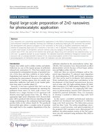
Recently, Huang et al. [79] made use of an anodic aluminium oxide (AAO) template
mask to produce Si nanowires by catalytic etching. For the reduction-oxidation (redox)
reaction in the catalytic etching process to occur, the catalyst needs to have a higher
electronegativity than Si so that electrons can be pulled away from Si atoms and the
oxidation of Si can take place [97]. In the work of Huang et al., a non-catalyst metal
that has a lower electronegativity than Si, such as chromium (Cr), was deposited onto
the AAO and used as a blocking material for the catalytic etching process. After
removing the AAO, a blanket layer of Au catalyst was deposited to produce Cr/Au
dots (at regions which are originally the pores of the AAO) and Si regions covered by
Au. Those areas of Si protected by the Cr/Au dots will remain after etching in the
HF/H2O2 solution, leaving behind regular array of Si nanowires with diameters that
can be adjusted depending on the pore diameter in the AAO mask. In this work,
experiments were carried out to investigate the effect of a bi-layer of two different
metals on catalytic etching of Si so as to understand better the actual mechanism
involved.
5.2 Effect of the metal film thickness on the etching process
HF of 4.6M and H2O2 of 0.44M were used as the etching solution in this experiment.
The samples were cleaned as discussed in the sample preparation section in Chapter 3.
Since Cr/Au was verified to be an effective protective metal layer that can block
etching [79], Cr/Au (10/30 nm) markers were prefabricated to make comparison with
Catalytic Etching Mechanism 95
the surrounding etched Si areas not covered by the markers. Using a standard optical
lithography process, micron-sized marker patterns, formed by 10 nm Cr and 30 nm Au
through evaporation, were formed on a Si (100) surface. The Si (100) substrate with
the markers were then used as the starting substrate for deposition of the bi-layer
metals before subjecting the samples to chemical etching in the HF/H2O2 etching
solution. The marker regions were not expected to be etched as the underlying Si in
these regions are covered by the Cr/Au (10/30 nm) layer and another bi-layer metal,
and Cr/Au (10/30 nm) had been demonstrated to block the chemical etching [79]. As
for the remaining non-marker regions where the underlying Si was just covered by the
bi-layer metal, whether chemical etching takes place or not depended on the bi-layer
metal materials selected and the thickness of the layers.
Figure 43 shows the SEM images of two etched Si samples with Ti/Au bi-layer of
different thickness deposited on top of the Si marker sample. Both samples were
etched in a fresh solution with the same HF/H2O2 composition for 5 minutes. Figure
43(a) shows the sample that has a bi-layer of Ti/Au (5/10 nm) where 5 nm of Ti was
first deposited on the Si substrate with markers, followed by 10 nm of Au. It can be
seen clearly that chemical etching has taken place in the non-marker regions. The
etched depth was about 6 µm. In Figure 43(b), a bi-layer of Ti/Au (5/15 nm) was
deposited on the Si substrate with markers and the sample was etched for 5 minutes;
however, there was only very limited (negligible) etching observed in the non-marker
regions. Although Ti itself has lower electronegativity than Si and can act as a
blocking layer in etching, Ti will react with HF and get dissolved. The only difference
in the two samples is the thickness of the protective Au layer above Ti. From the
results, it shows that at least 15 nm of Au is required to protect the Ti underneath.
Catalytic Etching Mechanism 96
Therefore only a bi-layer of Ti/Au with 15 nm of Au on 5 nm of Ti will be able to be
used as an effective blocking layer for catalytic etching.
Figure! "#! $%&! '()*+! ,-! ./+! +.0/+1! $'! ()23+2! 4)(56+! 7'./! 8)9! :';<=! 8>;?@! A(9! )A1! 8B9!
:';<=!8>;?>!A(9!B'C6)D+2!1+5,4'.+1!,A!./+!$'!()23+2!4)(56+E!
A similar experiment was repeated with Cr/Au as the blocking bi-layer metal with two
different thicknesses of the Au layer (10 nm and 15 nm) and 5 nm of Cr investigated.
Both Figures 44(a) and 44(b) show some chemical etching in the non-marker regions,
although this is somewhat limited, after the samples were immersed in the HF/H2O2
etching solution for 5 minutes. This shows that 5 nm of Cr is still sufficient as a
blocking layer. This is due to the fact that Cr does not react with HF or H2O2.
Although 10 nm of Au is not enough to block HF and H2O2, the Cr/Au blocking layer
still remained intact after the reaction. Therefore, summarizing the results from Figures
43 and 44, the reactivity of the blocking material with the etching solution has to be
taken into account when choosing an appropriate blocking material in addition to the
thickess of the bi-layer.
Catalytic Etching Mechanism 97
!"#$%&'((')*+'",-#&'./'01&'&021&3')"'4-,56&'7"01'8-9':%;<$'8=;>?'@,9'-@3'8A9':%;<$'8=;>='
@,9'A"B6-C&%'3&5.4"0&3'.@'01&')"',-%D&%'4-,56&E'
5.3 XPS results on the catalytic etching mechanism
To check if Si has diffused through the catalyst metal layer during the catalytic etching
process, XPS technique is used. Figure 45 shows the sample where XPS analysis was
carried out. 21nm of Au was deposited on a Si substrate with a shadow mask.
!"#$%&' (=' )-,56&' 7"01' 2"%2$6-%' <$' 3.04' ./' 3"//&%&@0' 4"F&' 7&%&' 4$AG&20&3' 0.' 4$A40-@0"-6'
&021"@#E'HI)'-@-6C4"4'7-4'2-%%"&3'.$0'.@'01&'2"%2$6-%'<$'3.0'-4'"@3"2-0&3'AC'01&'%&3'-%%.7E'
Catalytic Etching Mechanism 98
Figure 46 shows the XPS spectra obtained at the Au dot indicated above. Different
colors were used for the spectra obtained at different timing of sputtering during depth
profiling. A net offset was added to each line so that the graphs can be seen more
clearly for analysis. The Si2p peak at 99.7eV can be clearly observed so it was
suspected that there was substantial diffusion of Si species from the substrate through
the metal catalyst to the surface of catalyst layer.
!"#$%&'()'*+,'-.&/0%1'2301"4&5'6%27'08&'1419:-"-'26'08&'-.20'-82;4'"4'6"#$%&'(<'
However, a SEM image obtained in figure 47 shows that there were cracks and
trenches on the Au layer. Since the spot size of XPS is relatively large, the large area
beam will cover regions with the metal film with cracks as well as those without
cracks. The underlying Si could give rise to the Si2p peaks obtained in the XPS spectra.
AES was used subsequently for further investigation with the consideration that AES
Catalytic Etching Mechanism 99
has a much smaller spot size than XPS. Thus, it can be performed on an area without
cracks.
!"#$%&'()'*"#+',-#."/"0-1"2.'345'",-#&'2/'1+&'6$'721'/%2,'/"#$%&'(8'-/1&%'&10+9'
5.4 AES results to further investigate the catalytic etching
mechanism
To further investigate whether Si has diffused from the underlying Si substrate through
the metal catalyst layer during the catalytic etching process, Auger electron
spectroscopy (AES) was used to test if Si signals can be detected on the Au catalyst
surface of the Si sample that was subjected to etching for a sufficient duration.
Another batch of sample was fabricated exactly the same way as the one used for the
Catalytic Etching Mechanism 100
XPS analysis in Chapter 5.3. After cleaning, 21nm of Au was deposited on the Si
substrate with a shadow mask. Figure 48 shows the sample locations 1 and 2 chosen
for the AES analysis. Figure 49 shows the AES spectra of the two locations before ion
etch while Figure 50 shows the AES spectra after ion etch to remove a layer of
approximately 1 nm thickness. The AES analysis shows that Si is only present at an
appreciable detectable level in a thin (approximately 1 nm) layer on the surface as seen
from Figure 49. This could be due to redeposition of Si species or etched products in
the solution. After removal of a 1 nm surface layer, there is no detectable Si signal as
seen from Figure 50. However, there is no indication that the Si signal present in
Figure 49 is associated with pinholes or grain boundaries of the Au layer on the Si
sample which could have aided any Si diffusion from the underlying substrate.
Therefore in summary, the AES analysis shows that there is no evidence of Si atoms
diffusing up through the Au metal layer from the underlying Si substrate during the
catalytic etching process. It is likely that the etching of this sample took place at the
interface between the metal catalyst layer and the Si substrate, rather than at the
interface between metal catalyst and the etchant solution as the latter would require Si
atoms to diffuse from the underlying substrate through the metal catalyst to the
metal-solution interface. The implication for etching to take place at the interface
between the metal catalyst layer and the Si substrate is that it is necessary for the
etchant species in the solution to be transported to the Si-metal interface. This will not
be a problem if the metal catalyst is in the form of small area structures, such as Au
nanodots on Si obtained from an AAO template mask. However if the Si substrate is
covered by a continuous layer of large area metal catalyst, it will make the transport of
the etchant species to the Si-metal interface difficult unless there are cracks or pinholes
Catalytic Etching Mechanism 101
in the metal catalyst layer which allows the etchant species to seep through.
!"#$%&'()'*+,-.&'./0+1"/23'4'+25'6'+2+.73&5'"2'18&'9/../:"2#';<*'3-&01%+'38/:2'"2'
3$=3&>$&21'9"#$%&3?'@8&'3+,-.&':+3'9+=%"0+1&5'=7'5&-/3"1"2#'642,'/9';$'/2'*"':"18'+'
38+5/:',+3A?' '
Catalytic Etching Mechanism 102
!"#$%&'()'*+,'-.&/0%1'2%34'53/10"36-'7'168'9:';<&'-$%21/&'32'0<&'4&015'=1-'630'"36'&0/<&8:'
Catalytic Etching Mechanism 103
!"#$%&'()'*+,'-.&/0%1'2%34'53/10"36-'7'168'9'120&%'"36'&0/:;'*..%3<"410&5='7'64'32'410&%"15'
2%34'0:&'-14.5&'-$%21/&'>1-'%&43?&8'120&%'0:&'"36'&0/:;'
5.4 Effect of the size of the metal mask on the etched
structure
It is of interest to find out if the anisotropic nature of the etching process will be
affected by the size of the metal catalyst since most of the features required for the
modern technology have to be of nano-size dimensions. Triangular Cr/Au (10/30 nm)
masks (see Figures 51 and 52) with about 100 nm long edge were deposited on lowly
doped (160!cm) n-type Si (100) using an electron beam lithography process. An Au
Catalytic Etching Mechanism 104
catalyst layer of 7nm was deposited on the substrate by thermal evaporation. The
samples were then etched in HF of 4.6M and H2O2 of 0.44M for 40 seconds. As
mentioned previously, Cr/Au (10/30 nm) regions were able to block the chemical
etching of Si.
!"#$%&'()'*+,'"-.#&'/0'12&'3.3/4"5&'6%78$'-.49:'
!"#$%&'(;'8'2"#2'-.#3"0"<.1"/3'"-.#&'/0'12&'3.3/4"5&'6%78$'-.49:'
Catalytic Etching Mechanism 105
Figure 53 shows the triangular shaped Si nanowires produced after the chemical etch.
The geometry of the triangular mask was preserved during the etch for most of the
nanowires. The side walls for some of the nanowires show the presence of facets after
the chemical etching. This shows that the etching can be anisotropic even for
extremely small features. Silicon nanowires with such special geometry could be of
interest
for
various
applications
in
electronics,
photonics,
photovoltaics,
thermoelectrics, etc.
!"#$%&'()'*+,'"-.#&'/0'12&'1%".3#$4.%'5"44.%'61%$71$%&'.01&%'7.1.481"7'&172"3#'0/%'9:'6&7/3;6<'
Catalytic Etching Mechanism 106
5.5 Summary
In summary, the thickness of the blocking bi-layer required for the catalytic etching
process was investigated. It is important to look into the reaction of the blocking
materials with the etchant solution. The mechanism of the catalytic etching was also
investigated with AES. It was found that there is no significant diffusion of Si from the
underlying substrate through the metal catalyst during the catalytic etching process. It
is therefore likely that catalytic etching of Si took place at the interface between the
metal catalyst layer and the Si substrate, rather than at the interface between metal
catalyst and the etchant solution as the latter would require Si atoms to diffuse from
the underlying substrate through the metal catalyst to the metal-solution interface. Last
but not least, the catalytic etching was tested with a nano-size mask produced by
electron beam lithography with special geometry (triangular shape) features. The result
shows that the etching process can remain anisotropic even with the nano-size mask.
Conclusion 107
Chapter 6 Conclusion
6.1
Conclusion
In conclusion, the fabrication of Ge nanowires and characterization of its thermal
conductivity (k) were investigated. Experimental measurements show a 6 times
decrease in the k value of the Ge nanowires as compared to bulk Ge. However, the
actual k value could be lower if possible source of errors introduced by heat loss to the
surrounding and the substrate could be minimized.
The catalytic etching fabrication process for Si nanowires was also investigated.
Various aspects such as the mechanism of catalytic etching, consideration in choosing
appropriate blocking materials and nanowires with special geometry were investigated
in this work. It was found that there is no significant diffusion of Si from the
underlying substrate through the metal catalyst during the catalytic etching process. It
is therefore likely that catalytic etching of Si took place at the interface between the
metal catalyst layer and the Si substrate, rather than at the interface between metal
catalyst and the etchant solution as the latter would require Si atoms to diffuse from
the underlying substrate through the metal catalyst to the metal-solution interface.
6.2
Recommendations for future work
For future work, the thermal conductivity measurement can be performed on a special
substrate where there are trenches between electrodes so that the heat loss to the
surrounding can be minimized. Multiple Ge nanowires, rather than just a single Ge
Conclusion 108
nanowire, can also be tested with the characterization setup. Lastly, Ge nanotubes and
Si nanowires of special geometry mentioned in chapter 5.4 can be tested to investigate
the effect of the structure and shape on the thermal conductivity of the materials. Such
unique geometry can potentially reduce the k value further, thus enhancing the
efficiency of the nanowire as a thermoelectric material.
Reference 109
References
1.
M.A. Green, Third Generation Photovoltaics: Advanced Solar Energy
Conversion, Springer, New York, 2003.
2.
G.W. Lewis, "Solar energy conversion", Phys. Today 60 (3): pp. 37-42, 2007.
3.
A.I. Boukai, Y. Bunimovich, J. Tahir-Kheli, J.K. Yu, W.A. Goddard III and
J.R. Heath, "Silicon nanowires as efficient thermoelectric materials", Nature
451: pp. 168-171, 2008.
4.
A.I. Hochbaum, R. Chen, R.D. Delgado, W.J. Liang, E.C. Garnett, M. Najarian,
A. Majumdar and P.D. Yang, "Enhanced thermoelectric performance of rough
silicon nanowires", Nature 451: pp. 163-167, 2008.
5.
C.B. Vining, "Desperately seeking silicon", Materials Science 451: pp.
132-133, 2008
6.
L. Lu, W. Yi, and D.L. Zhang, "3 method for specific heat and thermal
conductivity measurements", Review of Scientific Instruments, 72(7), 2001
7.
D.T. Morelli, T. Caillat, J.-P. Fleurial, A. Borshchevsky, J. Vandersande and B.
Chen, "Low-temperature transport properties of p-type CoSb3", Phys. Rev. B:
Condens. Matter Mater. Phys., 51:9622, 1995
8.
G. S. Nolas, D.T. Morelli and T. M. Tritt., "Skutterudites: a
phonon-glass-electron crystal approach to advanced thermoelectric energy
conversion applications", Annu. Rev. Mater. Sci., 29:89, 1999
9.
T. Caillat, A.B., and J.-P. Fleurial. J. Appl. Phys., 1996. 80:4442.
10.
Y.-M.L., PhD thesis, Massachusetts Institute of Technology, 2003.
11.
L. D. Hicks, T.C. Harman, X. Sun, and M.S. Dresselhaus, "Experimental study
of the effect of quantum-well structures on the thermoelectric figure of merit",
Phys. Rev. B:. Condens. Matter Mater. Phys., 53:R10493, 1996
12.
G.S. Nolas, J. Yang, T.P. Hogan, D.C. Johnson, "Thermoelectric Materials
2003 - Research and Applications Symposium", Mater. Res. Soc. Symposium
Proceedings, Vol.793, 2004
13.
T. M. Tritt, G.M. Nolas, M. G. Kanatzidis, D. Mandrus, "Thermoelectric
Materials–The Next Generation Materials for Small-Scale Refrigeration and
Power Generation Applications, MRS Symp.", Materials Research Society
Press, 2000.
Reference 110
14.
V.A. Nemchinsky, B.Ya. Moizhes, "Plasma parameters near a small anode in a
high-pressure arc", Journal of Physics D (Applied Physics), 27, pp.2515-2521,
1992.
15.
J. Yang, R. Funahashi, G. S. Nolas, "Materials and Technologies for Direct
Thermal-to-Electric Energy Conversion", Materials Research Society Press,
p.512, 2005.
16.
M.S. Dresselhaus., J.P. Heremans, "Thermoelectrics Handbook: Macro to
Nano", CRC Press, Boca Raton, FL, 2006.
17.
C.B. Vining, "Desperately seeking silicon Nature" Materials science, 451: p.
168-171, 2008
18.
A.J. Hochbaum, R. Chen, R.D. Delgado, "Enhanced thermoelectric
performance of rough silicon nanowires" Nature, 451, pp.163-167, 2008
19.
G.S. Nolas, J. Sharp and H.J. Goldsmid, "Basic Principles and New Materials
Development", Thermoelectrics, Ch. 3, 2001
20.
M. Asheghi, Y.K. Leung, S.S. Wong, and K.E. Goodson, "Phonon-boundary
scattering in thin silicon layers", Appl. Phys. Lett., 71: pp. 1798–1800, 1997
21.
M. Asheghi, M.N. Touzelbaev, K.E. Goodson, Y.K. Leung and S.S. Wong,
"Temperature-dependent thermal conductivity of single-crystal silicon layers in
SOI substrates", J. Heat Transf., 120: pp. 30–36, 1998
22.
Y.S. Ju, K.E. Goodson, "Phonon scattering in silicon films with thickness of
order 100 nm", Appl. Phys. Lett., 74: pp. 3005–3007, 1999
23.
N.A. Melosh, A. Boukai, F. Diana, B.Gerardot, "Ultra-high density nanowire
lattices and circuits" Science, 300: pp. 112–115, 2003
24.
K.Q. Peng, Y.J. Yan, S.P. Gao, and J. Zhu, "Synthesis of large-area silicon
nanowire arrays via self-assembling nanochemistry", Adv. Mater., 14: pp.
1164–1167, 2002
25.
K.Q. Peng, Y. Yan, S. Gao, J. Zhu, "Dendrite-assisted growth of silicon
nanowires in electroless metal deposition", Adv. Funct. Mater., 13: pp.
127–132, 2003
26.
K. Peng, Y. Wu, H. Fang, "Uniform, axial-orientation alignment of
one-dimensional single crystal silicon nanostructure arrays", Angew. Chem. Intl
Edn., 44: pp. 2737–2742, 2005
27.
Z. Wang, N. Mingo, "Diameter dependence of SiGe nanowire thermal
Reference 111
conductivity", Applied Physics Letters, 97, 101903, 2010
28.
H. Kim, H.J. Choi, and W. Kim, "Thermal conductivities of Si1!xGex
nanowires with different germanium concentrations and diameters", Applied
Physics Letters, 96, 233106, 2010
29.
J. Chen, G. Zhang, and B. Li, "Tunable thermal conductivity of Si1!xGex
nanowires" Applied Physics Letters, 95, 073117, 2009
30.
R. Prasher, "Thermal conductivity of tubular and core/shell nanowires",
Applied Physics Letters, 89, n 6, 2006
31.
L.D. Hicks, M.S. Dresselhaus, "Thermoelectric figure of merit of a
one-dimensional conductor", Phys. Rev. B: Condens. Matter Mater. Phys., 47:
pp. 16631–16634, 1993
32.
G.D. Mahan, J.O. Sofo, "The best thermoelectric", Proc. Natl Acad. Sci, 93: pp.
7436–7439, 1996
33.
T.E. Humphrey, H. Linke, "Reversible thermoelectric nanomaterials", Phys.
Rev. Lett., 94: p. 096601, 2005
34.
A. Majumdar, "Enhanced thermoelectricity in semiconductor nanostructures",
Science, 303: pp. 777–778, 2004
35.
W. Tian, R. Yang, "Thermal conductivity modeling of compacted nanowire
composites", Journal of Applied Physics, 101, pp.543201-543205, 2007
36.
N. Mingo and L. Yang, "Predicting the Thermal Conductivity of Si and Ge
Nanowires", Nano Letters, 3: pp. 1713-1716, 2003
37.
D. Wang, Y.L. Chang, Z. Liu, H. Dai, "Oxidation Resistant Germanium
Nanowires: Bulk Synthesis, Long Chain Alkanethiol Functionalization and
Langmuir-Blodgett Assembly", Journal of the American Chemical Society, 127,
pp. 11871-11875, 2005
38.
X.F. Duan, C.M. Lieber, "General synthesis of compound semiconductor
nanowires", AdV. Mater., 12: pp. 298-302, 2000
39.
Y.F. Zhang, N. Wang, D.P. Yu, C.S. Lee, I. Bello, S.T. Lee, "A Novel Low
Temperature Synthesis Method For Semiconductor Nanowires", Appl. Phys.
Lett., 72: pp. 1835-1837, 1998
40.
M.S. Gudiksen, J. Wang, C.M. Leiber, "Growth of single crystal nanowires",
Journal of Physical Chemistry B, 122: pp. 8801- 8802, 2000
Reference 112
41.
T.J. Trentler, K.M. Hickman, S.C. Goel, A.M. Viano, P.C. Gibbons, W.E.
Buhro, "Solution-liquid-solid growth of crystalline III-V semiconductors: an
analogy to vapor-liquid-solid growth", Science, 270: pp. 1791-1793, 1995
42.
T.J. Trentler, K.M. Hickman, A.M. Viano, M.Y. Chiang, A.M. Beatty, P.C.
Gibbons, W.E. Buhro, "Nanodevices by using semiconductor nanowires", J.
Am. Chem. Soc., 119: pp. 2172-2181, 1997
43.
J.R. Heath, F.K. LeGoues, "A liquid solution synthesis of single-crystal
germanium quantum wires", Chem. Phys. Lett., 208: pp. 263-268, 1993
44.
A.P. Levitt, "Whisker Technology", Wiley-Interscience, New York, 1970.
45.
R.S. Wagner and W.C. Ellis, "VLS mechanism", Appl. Phys. Lett., 4: pp. 89-91,
1964
46.
Y. Wu, P. Yang, "Direct Observation of Vapor-Liquid-Solid Nanowire
Growth", J. Am. Chem. Soc., 123: pp. 3165-3166, 2001
47.
M. Brust, D. Bethell, D. J. Schiffrin, R. Whyman, "Synthesis of
thiol-derivatised gold nanoparticles in a two-plate liquid-liquid system", J.
Chem. Soc., Chem. Commun., 801, 1994
48.
X. Lu, T. Hanrath, K.P. Johnston, B.A. Korgel, "Growth of single crystal
nanowires", Adv. Mater., 15(5): pp. 437-440, 2003
49.
Y. Cui, M.S. Gudiksen, J. Wang, C.M. Leiber, "Structural and functional
imaging silicon nanowires", Appl. Phys. Lett., 78: pp. 2214-2216, 2001
50.
D. Wang, H. Dai, "Germanium nanowires: from synthesis, surface chemistry,
and assembly to devices", Appl. Phys. A, 85: pp. 217-255, 2006
51.
Y. Wu, P. Yang, "Germanium Nanowire Growth via Simple Vapor Transport",
Chem. of Mater, 12: pp. 605-607, 2000
52.
T.I. Kamins, X. Li, S. William, "Growth and Structure of Chemically Vapor
Deposited Ge Nanowires on Si Substrates", Nano Letters, 4(3): pp. 503-506,
2004
53.
V. Schmidt, H. Riel, S. Senz, S. Karg, W. Riess, U. Go¨sele, "Realization of a
silicon nanowire vertical surround-gate field-effect transistor" Small, 2: pp.
85-88, 2006
54.
J. Goldberger, A.I. Hochbaum, R. Fan, P. Yang, "Silicon vertically integrated
nanowire field effect transistors" Nano Lett., 6: p. 973-977, 2006
55.
K.Q. Peng, Y. Wu, Y. Yan, S.T. Lee, J. Zhu, "Aligned single-crystalline Si
Reference 113
nanowire arrays for photovoltaic applications", Small, v1, pp. 1062–1067, 2005
56.
B.Z. Tian, X. Zheng, T.J. Kempa, Y. Fang, N. Yu, G. Yu, J. Huang, and C.M.
Lieber, "Coaxial silicon nanowires as solar cells and nanoelectronic power
sources", Nature, 449: pp. 885–890, 2007
57.
Y. Cui, Q. Wei, H. Park, C.M. Lieber, "Nanowire nanosensors for highly
sensitive and selective detection of biological and chemical species", Science,
293: pp. 1289-1292, 2001
58.
F. Patolsky, G. Zheng, C.M. Lieber, "Fabrication of silicon nanowire devices
for ultrasensitive, label-free, real-time detection of biological and chemical
species", Nat. Protoc., 1: pp. 1711-1724, 2006
59.
C.K. Chan, H. Peng, G. Liu, K. McIlwrath, X.F. Zhang, R.A. Huggins, and Y.
Cui, "High-performance lithium battery anodes using silicon nanowires", Nat.
Nanotechnol., 3: pp. 31-35, 2008
60.
K.H. Hong, J. Kim, S.H. Lee, J.K. Shin, " Strain-Driven Electronic Band
Structure Modulation of Si Nanowires", Nano Lett., 8: pp. 1335-1340, 2008
61.
A.K. Buin, A. Verma, A. Svizhenko, M.P. Anantram, "Enhancement of hole
mobility in [110] Silicon Nanowires", Nano Lett., 8: pp. 760-765, 2008
62.
D.D.D. Ma, C.S. Lee, F.C.K. Au, S.Y. Tong and S.T. Lee, "Small-Diameter
Silicon Nanowire Surfaces", Science, 299: pp. 1874-1877, 2003
63.
C.R. Leao, A. Fazzio and A.J.R. da Silva, "Si Nanowires as Sensors: Choosing
the Right Surface", Nano Lett., 7: pp. 1172-1177, 2007
64.
D. Lyons, M. Ryan, M. Morris, J. Holmes, "Tailoring the Optical Silicon
Nanowire Arrays through Strain", Nano Lett., 2: pp. 811-816, 2002
65.
H. Fang, X. Li, S. Song, Y. Xu, J. Zhu, "Fabrication of slantingly-aligned
silicon nanowire arrays for solar cell applications", Nanotechnology, 19, 2008
66.
W. Haensch, E. J. Nowak and R.H. Dennard, "Silicon CMOS Devices Beyond
Scaling", IBM J. Res. DeV., 50: pp. 339-361, 2006
67.
B.L., Fuhrmann, S. Hartmut, H.R. Ho¨che, L. Schubert, P. Werner and U.
Go¨sele, "Ordered Arrays of Silicon Nanowires Produced by Nanosphere
Lithography and Molecular Beam Epitaxy", Nano Lett., 5: pp. 2524–2527,
2005
68.
Y. Wang, S. Volker, S. Senz and U. Go¨sele, "Epitaxial growth of silicon
nanowires using an aluminium catalyst", Nature Nanotech., 1: pp. 186–189,
Reference 114
2006
69.
Y. Wu, Y. Cui, L. Huynh, C.J. Barrelet, D.C. Bell, C.M. Lieber, "Controlled
Growth and Structures of Molecular-Scale Silicon Nanowires", Nano Lett., 4:
pp. 433-436, 2004
70.
V. Schmidt, S. Senz, U. Go¨sele, "Diameter-Dependent Growth Direction of
Epitaxial Silicon Nanowires", Nano Lett., 5: pp. 931-935, 2005
71.
C.L. Lee, K.Tsujino, Y. Kanda, S. Ikeda and M. Matsumura, "Pore formation
in silicon by wet etching using micrometre-sized metal particles as catalysts",
Journals of Materials Chemistry, pp. 1015-1020, 2008
72.
N. Megouda, T.Hadjersi, G. Piret, R. Boukherroub, O. Elkechai, "Au-assisted
electroless etching of silicon in aqueous HF/H2O2 solution", Applied Surface
Science, 255: pp. 6210-6216, 2009
73.
H. Asoh, F.Arai, S. Ono, "Effect of noble metal catalyst species on the
morphology of macroporous silicon formed by metal-assisted chemical etching.
Electrochimica Acta", 54: pp. 5142-5148, 2009
74.
M.L. Chouroua, K. Fukami, T. Sakkaa and Y.H. Ogata, S. Virtanenc,
"Metal-assisted etching of p-type silicon under anodic polarization of HF
solution with and without H2O2", Electrochimica Acta, 55: pp. 903-912, 2010
75.
Y.M. Yang, P.K.Chu, Z.W. Wu , S.H. Pu , T.F. Hung, and G.X.Qian, K.F. Huo,
W.J. Zhang, X.L. Wu, "Catalysis of dispersed silver particles on directional
etching of silicon", Applied Surface Science, 254: pp. 3061-3066, 2008
76.
Z.P. Huang, X. Zhang, M. Reiche, L. Liu, W. Lee, T. Shimizu, S. Senz, and U.
Gosele, "Extended Arrays of Vertically Aligned Sub-10 nm Diameter [100] Si
Nanowires by Metal-Assisted Chemical Etching" Nano Lett., 8(9): pp.
3046-3051, 2008
77.
Z.P. Huang, H. Fang, J. Zhu, "Fabrication of Silicon Nanowire Arrays with
Controlled Diameter", Adv. Mater., 19: pp. 744–748, 2007
78.
K.Q. Peng, M. L. Zhang, A. Lu, N.B. Wong, R. Zhang, S.T. Lee, "Ordered
silicon nanowire arrays via nanosphere lithography and metal-induced etching",
Appl. Phys. Lett., 90., p.163123 2007
79.
J.Q. Huang, S.Y. Chiam, H.H. Tan, S. Wang, and W.K. Chim, "Fabrication of
Silicon Nanowires with Precise Diameter Control Using Metal Nanodot Arrays
as a Hard Mask Blocking Material in Chemical Etching", Chem. Mater, 22: pp.
4111-4116, 2010
Reference 115
80.
K.Q. Peng, A.Lu, R. Zhang and S.T. Lee, "Motility of Metal Nanoparticles in
Silicon and Induced Anisotropic Silicon Etching", Adv. Funct. Mater., 18: pp.
3026-3035, 2008
81.
S.B. Cronin, Y.M. Lin, M.R. Black, O. Rabin, and M. S. Dresselhaus,
"Thermoelectric transport properties of single bismuth nanowires", Proc. 21st
Int. Thermoelectronics Conf., pp. 243–248, 2002
82.
D. Li, P. Kim, L. Shi, P. Yang, and A. Majumdar, "Thermal conductivity of
individual silicon nanowires", Appl. Phys. Lett., 83: pp. 2934–2936, 2003
83.
L. Shi, C. Yu,W. Jang, D. Kim, Z. Yao, P. Kim, and A. Majumdar, "Measuring
thermal and thermoelectric properties of one-dimensional nanostructures using
a microfabricated device", J. Heat Transfer, 125, p.881, 2003
84.
D.H. Jung, T.W. Kwon, D.J. Bae, I.K. Moon and Y.H. Jeong, "Fully automated
dynamic calorimeter", Meas. Sci. Technol., 3: pp. 475-484, 1992
85.
D.G. Cahill, H.E. Fischer, T. Klitsner, E.T. Swartz, and R.O. Pohl, "Thermal
conductivity of thin films: measurements and understanding", J. Vac. Sci.
Technol., 7: p. 1259, 1989
86.
D.G. Cahill, "Thermal conductivity measurement from 30 to 750 K: the 3w
method", Rev. Sci. Instrum., 61: p. 802, 1990
87.
R. Frank and J. Fricke, "Determination of thermal conductivity by a combined
3!/decay technique", Rev. Sci. Instrum., 64: p. 760, 1993
88.
Y. Zhang, A. Shakouri, D. Li, A. Majumdar, Y. Wu, R. Fan, and P.D. Yang,
"Characterization of Heat Transfer Along a Silicon Nanowire Using
Thermoreflectance
Technique",
IEEE
TRANSACTIONS
ON
NANOTECHNOLOGY, 5(1): pp. 67-74, 2006
89.
M. Fujii, X.Zhang, H.Q. Xie, H. Ago, K.Takahashi, T. Ikuta, H.Abe and
T.Shimizu, "Measuring the Thermal Conductivity of a Single Carbon
Nanotube", Physical Review Letters, 065502, 2005
90.
G.B.M. Fiege†, A. Andreas, R. Heiderhoff and L.J. Balk, "Quantitative thermal
conductivity measurements with nanometer solution", J. Phys. D: Appl. Phys.,
32: pp. L13–L17, 1999
91.
A. Molle, M.N.K. Bhuiyan, G. Tallarida, M. Fanciulli, "Formation and stability
of germanium oxide induced by atomic oxygen exposure", ScienceDirect, 9: pp.
673-678, 2006
92.
B. Lamontagne, E.Sacher, M.R. Wertheimer, "The Au/Si( 100) ( 1 x 1)-H
Reference 116
interface, as studied by XPS and AFM: a model of the interfacial reaction",
Applied Surface Science, 78: pp. 399-411, 1994
93.
M. Iwami, M. Kusaka, M. Hirai, M. Kubota, H. Tochihara and Y. Murata,
"Mechanism of alloy formation due to noble metal deposition on silicon
surfaces at room temperature. Chemical bonding model", Surface Science,
41/42: p. 97, 1989
94.
W. Lu, C.M. Lieber, "Semiconductor nanowires", Journal of Physics D:
Applied Physics, 39: pp. 387-406, 2006
95.
Y. Wang, T. T. Ho, L. Pan, S. W. Novak, E. C. Dickey, J. M. Redwing, and T.
S. Mayer, "Use of phosphine as an n-type dopant source for vapor-liquid-solid
growth of silicon nanowires", Nano Letters, 5: pp. 2139-2143, 2005
96.
L.Yang and N. Mingo, "Predicting the Thermal Conductivity of Si and Ge
Nanowires", Nano Lett., 3(12): pp. 1713-1716, 2003
97.
K.H. Peng, J. Hu, Y. Yan, Y. Wu, H. Fang, Y. Xu, S.T. Lee and J. Zhu,
"Fabrication of Single-Crystalline Silicon Nanowires by Scratching a Silicon
Surface with Catalytic Metal Particles", Adv. Funct. Mater., 16: pp. 387-394,
2006