Timing analysis of concurrent programs running on shared cache multi cores
Bạn đang xem bản rút gọn của tài liệu. Xem và tải ngay bản đầy đủ của tài liệu tại đây (791.62 KB, 50 trang )
TIMING ANALYSIS OF CONCURRENT
PROGRAMS RUNNING ON SHARED CACHE
MULTI-CORES
LI YAN
M.Sc., NUS
A THESIS SUBMITTED
FOR THE DEGREE OF MASTER OF SCIENCE
DEPARTMENT OF COMPUTER SCIENCE
NATIONAL UNIVERSITY OF SINGAPORE
2010
Acknowledgements
I would like to thank my supervisor Professor Tulika Mitra for her professional guidance and her invaluable advice and comments for the thesis during
my study.
Especially thanks go to Professor Abhik Roychoudhury for his guidance as
well as helpful suggestions.
I would like to thank Vivy Suhendra and Liang Yun who have collaborated
with me and have given me continue guidance through the last year.
My acknowledgements go out to all my friends Shi Chenwei, Zhen Hanxiong
for their warm-hearted help and beneficial discussions.
Finally, heartful thanks go for my family for their support with heart and
soul.
All errors are my own.
i
Abstract
Memory accesses form an important source of timing unpredictability.
Timing analysis of real-time embedded software thus requires bounding the
time for memory accesses. Multiprocessing, a popular approach for performance enhancement, opens up the opportunity for concurrent execution.
However due to contention for any shared memory by different processing cores, memory access behavior becomes more unpredictable, and hence
harder to analyze. In this thesis, we develop a timing analysis method
for concurrent software running on multi-cores with a shared instruction
cache. We do not handle data cache, shared memory synchronization and
code sharing across tasks. The method progressively refines the lifetime estimates of tasks that execute concurrently on multiple cores, in order to estimate potential conflicts in the shared cache. Possible conflicts arising from
overlapping task lifetimes are accounted for in the hit-miss classification of
accesses to the shared cache, to provide safe execution time bounds. We
show that our method produces tighter worst-case response time (WCRT)
estimates than existing shared-cache analysis on a real-world embedded
application.
ii
CONTENTS
CONTENTS
Contents
1 Introduction
1
1.1
Motivation
. . . . . . . . . . . . . . . . . . . . . . . . . . . . . .
1
1.2
Organization of the Thesis . . . . . . . . . . . . . . . . . . . . . .
3
2 Background
4
2.1
Abstract Interpretation . . . . . . . . . . . . . . . . . . . . . . .
4
2.2
Message Sequence Charts . . . . . . . . . . . . . . . . . . . . . .
8
2.3
Message Sequence Graph . . . . . . . . . . . . . . . . . . . . . .
10
2.4
DEBIE Case Study . . . . . . . . . . . . . . . . . . . . . . . . . .
10
2.5
System architecture . . . . . . . . . . . . . . . . . . . . . . . . .
11
3 Literature Review
13
4 Contributions
15
5 Approach
16
5.1
Overview . . . . . . . . . . . . . . . . . . . . . . . . . . . . . . .
16
5.2
Illustration . . . . . . . . . . . . . . . . . . . . . . . . . . . . . .
19
5.3
Analysis Components . . . . . . . . . . . . . . . . . . . . . . . .
20
5.3.1
Intra-Core Cache Analysis . . . . . . . . . . . . . . . . . .
20
5.3.2
Cache Conflict Analysis . . . . . . . . . . . . . . . . . . .
23
5.3.3
WCRT Analysis . . . . . . . . . . . . . . . . . . . . . . .
25
Termination Guarantee . . . . . . . . . . . . . . . . . . . . . . .
28
5.4
iii
CONTENTS
CONTENTS
6 Experiments
31
6.1
Setup . . . . . . . . . . . . . . . . . . . . . . . . . . . . . . . . .
31
6.2
Comparison with Yan-Zhang’s method . . . . . . . . . . . . . . .
32
6.3
Set associative caches . . . . . . . . . . . . . . . . . . . . . . . .
36
6.4
Sensitivity to L1 cache size . . . . . . . . . . . . . . . . . . . . .
36
6.5
Sensitivity to L2 cache size . . . . . . . . . . . . . . . . . . . . .
37
6.6
PapaBench . . . . . . . . . . . . . . . . . . . . . . . . . . . . . .
37
6.7
Scalability . . . . . . . . . . . . . . . . . . . . . . . . . . . . . . .
38
7 Future Work
39
8 Conclusion
40
iv
LIST OF TABLES
LIST OF TABLES
List of Tables
1
Filter function . . . . . . . . . . . . . . . . . . . . . . . . . . . .
2
Access latency of a reference in best case and worst case given its
21
classifications . . . . . . . . . . . . . . . . . . . . . . . . . . . . .
26
3
Characteristics and settings of the DEBIE benchmark . . . . . .
33
4
Characteristics and settings of the Papa benchmark . . . . . . .
34
v
LIST OF FIGURES
LIST OF FIGURES
List of Figures
1
An example of CCS and ACS. . . . . . . . . . . . . . . . . . . . .
5
2
An example of must and may analysis. . . . . . . . . . . . . . . .
7
3
An example of persistence analysis. . . . . . . . . . . . . . . . . .
7
4
A simple MSC and a mapping of its processes to cores. . . . . . .
9
5
A multi-core architecture with shared cache. . . . . . . . . . . . .
11
6
A multi-core architecture with shared cache. . . . . . . . . . . . .
12
7
Our Analysis Framework . . . . . . . . . . . . . . . . . . . . . . .
16
8
The working of our shared-cache analysis technique on the example given in Figure 4 . . . . . . . . . . . . . . . . . . . . . . . . .
19
9
Intra-core cache analysis for L1 . . . . . . . . . . . . . . . . . . .
22
10
Intra-core cache analysis for L2 . . . . . . . . . . . . . . . . . . .
22
11
L2 cache conflict analysis . . . . . . . . . . . . . . . . . . . . . .
23
12
EarlistTime and LatestTime Computation . . . . . . . . . . . . .
27
13
Average number of task per set for different size of cache. . . . . . . .
31
14
Code size distribution of DEBIE benchmark. . . . . . . . . . . .
32
15
Comparison between Yan-Zhang’s method and our method and
the improvement of set associativity optimization. . . . . . . . .
16
17
35
Comparison of estimated WCRT between Yan-Zhang’s method
and our method for varying L1 and L2 cache sizes. . . . . . . . .
37
Runtime of our iterative analysis . . . . . . . . . . . . . . . . . .
38
vi
1
INTRODUCTION
1
1.1
Introduction
Motivation
Caches are commonly utilized to enhance performance in embedded computing systems. Cache management is handled by hardware, lending transparency
that, while desirable to ease programming effort, leads to unpredictable timing
behavior for real-time software. Worst-case execution time (WCET) analysis for
real-time applications requires that the access time for each memory access is
safely bounded, in order to guarantee that timing constraints are met. With
the presence of performance-enhancing features in today’s systems, this can be
a challenging feat. One such feature is multiprocessing, which opens the opportunity for concurrent execution and memory sharing, and at the same time
introduces the problem of estimating the impact of resource contention.
A lot of research efforts have been invested in modeling dynamic cache behavior in single-processing systems. In the context of instruction caches, a particularly popular technique is abstract interpretation [2, 24] which introduces the
concept of abstract cache states to represent complete possible cache contents
at a given program point, enabling subsequent Cache Hit-Miss Classification of
memory accesses into ‘Always Hit’, ‘Always Miss’, ‘Persistent/First Miss’, and
‘Not Classified’. The latency corresponding to each of these situations can then
be incorporated in the WCET calculation.
Hardy and Puaut [8] further extend the abstract interpretation method
to safely produce worst-case hit/miss access classification in multi-level setassociative caches. They address a main weakness in the previous cache hierarchy
analysis [14], where unclassified L1 hit/miss results have been conservatively interpreted as Always Miss in the WCET estimation. However, in the subsequent
L2 analysis, this interpretation will lead to the assumption that L2 is always
accessed for that reference. On set-associative caches with a Least Recently
Used replacement policy, the abstract cache state update may then arrive at
an over-optimistic estimation of the age of the reference in L2, leading to unsafe
1
1.1
Motivation
1
INTRODUCTION
classification of certain actual L2 misses as L2 hits. Hardy and Puaut’s approach
rectifies this problem by introducing the concept of Cache Access Classification
to model the propagation of access from a cache level to the level above it: Always, Never, or Uncertain. When a reference cannot be classified as Always Miss
nor Always Hit at L1, the access to L2 is Uncertain for that reference. For such
accesses, the L2 analysis joins the abstract cache state resulting from an actual
access and the abstract cache state corresponding to no access. Considering both
these cases avoids overlooking the situation that may give rise to an execution
time higher than the estimated WCET.
As multi-cores are increasingly adopted in high-performance embedded systems, the design choices for cache hierarcy also expand. While each L1 cache
is typically required to remain closely and privately adjoined to each processing
core in order to provide single-cycle latency, letting the multiple cores share a
common L2 cache is seen as beneficial in situations where memory usage is not
always balanced across cores. When L2 cache is shared, a core will be able to
occupy a larger share during its busy period, and relinquish the space to be used
by other cores when it is idle. This architecture is implemented for example
in Power5 dual-core chip [20], XBox360’s Xenon processor [5], and Sun UltraSPARC T1 [22]. Certainly, the analysis effort required for this configuration is
also more complex, as memory contention across the multiple cores significantly
affects the shared cache behaviour. In particular, accesses to the L2 cache originating from different cores may conflict in the shared cache. Thus, isolated cache
analysis of each task that does not account for this effect will not safely bound
the execution time of the task.
The only technique in literature that has addressed shared-cache analysis
so far is one by Yan and Zhang [26]. Their approach first applies abstract
interpretation to tasks independently and produce the hit-miss classification at
both L1 and L2. In the next step, conflicting cache lines across the multiple
processing cores are identified. If these lines were previously categorized as hits,
they will be converted to misses. In this approach, all tasks executing in a
different core than the one under consideration are treated as potential conflicts
2
1
INTRODUCTION
1.2
Organization of the Thesis
regardless of their actual execution time frame, thus the resulting estimate is
not tight. We also note that their work has not addressed the problem with
conservative multi-level cache analysis observed by [8] as elaborated above, thus
it will be prone to unsafe estimation when applied to set-associative caches. This
concern, however, is orthogonal to the issues arising from cache sharing.
Motivated by this situation, this thesis proposes a tight and safe multi-level
cache analysis for multi-cores that include a shared L2 cache. Our method
includes progressively tightening lifetime analysis of tasks that execute concurrently across the multiple cores, in order to identify potential contention in the
shared cache. Possible conflicts arising from overlapping task lifetimes are then
accounted for in the hit-miss classification of accesses to the shared cache.
1.2
Organization of the Thesis
We introduce some related fundamental concepts related to timing analysis of
multi-cores with a shared instruction cache in Section 2 and literature review
in Section 3. From section 4, we list our primary contributions devoted to
timing analysis for concurrent software running on multi-cores with a shared
instruction cache. Following that, our analysis framework is illustrated in Section
5. Estimation results are shown to validate our approach later in Section 6.
Finally, the thesis proposes the future work in Section 7 and concludes in Section
8.
3
2
2
BACKGROUND
Background
Static analysis of programs to give guarantees about execution time is a difficult
problem. For sequential programs, it involves finding the longest feasible path in
the program’s control flow graph while considering the timing effects of the underlying processing element. For concurrent programs, we also need to consider
the time spent due to interaction and resource contention among the program
threads.
What makes static timing analysis difficult? Clearly it is the variation in the
execution time of a program due to different inputs, different interaction patterns (for concurrent programs) and different micro-architectural states. These
variations manifest in different ways, one of the major variations being the time
for memory accesses. Due to the presence of caches in processing elements, a
certain memory access may be cache hit or miss in different instances of its execution. Moreover, if caches are shared across processing elements as in shared
cache multi-cores, one program thread may have constructive or destructive effect on another in terms of cache hits/misses. This makes the timing analysis of
concurrent programs running on shared-cache multi-cores a challenging problem.
We address this problem in our work. Before that, we will give some background
on Abstract Interpretation, Message Sequence Charts (MSCs) and Message Sequence Graphs (MSGs) — our system model for describing concurrent programs.
In doing so, we also introduce our case study with which we have validated our
approach. We conclude this section by detailing our system architecture — the
platform on which the concurrent application is executed.
2.1
Abstract Interpretation
In the context of instruction caches, a particularly popular technique is abstract
interpretation [2, 24] which introduces the concept of abstract cache states to
represent complete possible cache contents at a given program point, enabling
subsequent Cache Hit-Miss Classification of memory accesses into ‘Always Hit’,
4
2
BACKGROUND
2.1
Abstract Interpretation
‘Always Miss’, ‘Persistent/First Miss’, and ‘Not Classified’. The latency corresponding to each of these situations can then be incorporated in the WCET
calculation.
This approach works as follows [14, 21]:
Assume a two-way set-associative cache with four cache lines and Least Recently Used (LRU) replacement policy.
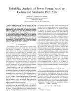
Firstly, the concrete cache state (CCS) given a program point is defined. The
concrete cache state is the exact result cache state for a given program point. In
this way, each concrete cache state represents a real cache state.
Next, the abstract cache state (ACS) given a program point is defined. Obviously, if we use CCS to do cache analysis, the possible cache states probably
will grow exponentially due to conditional executions or loops and thus renders
the problem to be unsolvable within finite time. To avoid this, an abstract cache
state is defined so that just one state can gather all possible occurring concrete
states for each program point.
Age 0
4
5
6
7
Set 0
Set 1
Set 2
Set 3
Age 1
0
1
2
3
9
4
9
6
7
CSS 1
10
0
5
2
3
4
5
10
7
CSS 2
0
1
6
3
4
0
9,5 5,1
10,6 6,2
7
3
ACS1
Figure 1: An example of CCS and ACS.
Figure 1 is an example of CCS and ACS. It shows a conditional execution.
Program line 9 is then-part while program line 10 is else-part. After the control
flow joins again, both CCS’ (that is CSS1 and CSS2 in the figure) represent
possible cache states and have to be considered for the remainder of program
5
2.1
Abstract Interpretation
2
BACKGROUND
execution. It also depicts the corresponding ACS (that is ACS1). There is only
one output ACS containing sets of program lines that may be cached at this
point of execution. In effect, the output CCS’ are merged into this output ACS.
Merging conserves space but reduces the amount of information. For example,
the output ACS does not show that either program lines 9 or 10 can be cached.
To catch as more information as possible, abstract semantics should consist
of an abstract domain and a set of proper abstract semantic functions, so called
transfer functions, for the program statements computing over the abstract domain. They describe how the statements transform abstract data. They must
be monotonic to guarantee termination. An element of the abstract domain represents sets of elements of the concrete domain. The subset relation on the sets
of concrete states determines the complete partial order of the abstract domain.
The partial order on the abstract domain corresponds to precision, i. e., quality
of information. To combine abstract values, a join operation is needed. In our
case this is the least upper bound operation, t, on the abstract domain, which
also defines the partial order on the abstract domain. This operation is used to
combine information stemming from different sources, e. g. from several possible
control flows into one program point.
We have three types of operations on ACS defined as following. To make
it clearly interpreted, we just assume LRU as the cache replacement strategy.
However, it can be extended to other cache replacement policies such as FIFO,
pseudo-LRU and so on which are explained specifically in [9]. Since each set
is independently updated when LRU cache replacement policy is adopted, we
illustrate operations of cache state using only one set of cache for simplicity.
Further, we assume a 4-way cache.
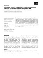
• Must Analysis: Must analysis determines the set of all memory blocks
that are guaranteed to be present in the cache at a given program point.
This analysis is similarly to do set intersection of multiple abstract cache
states where the position of a memory block is an upper bound of its age
among all the abstract cache states.
6
2
BACKGROUND
2.1
Age 0
Age 1
Age 2
Age 3
h
b, e
c, f
a
a, c
b
e
g
ACS1
ACS2
Result after must analysis
Abstract Interpretation
Result after may analysis
aa, c,
c h
b, e
f
g
b
c, e
a
Figure 2: An example of must and may analysis.
• May Analysis: The may analysis determines all memory blocks that
may be in the cache at a given program point. It is used to guarantee the
absence of a memory block in the cache. This analysis is similarly to do
set unions of abstract cache state where the position of a memory block is
a lower bound of its age among all the abstract cache states. Figure 2 is
an example of must and may analysis.
Age 0
Age 1
Age 2
Age 3
h
b, e
c, f
a
d, e
a, c
b
e
g
f, h
ACS1
ACS2
Result after persistence analysis
b
c
a, g
d, e, f, h
Figure 3: An example of persistence analysis.
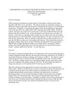
• Persistence Analysis: This analysis is used to improve the classification
of memory references. It collects the set of all memory blocks that are
never evicted from the cache after the first reference, which means that a
first execution of a memory reference may result in either a hit or a miss,
but all non-first executions will result in hits. This analysis is similarly to
7
2.2
Message Sequence Charts
2
BACKGROUND
do unions of abstract cache states where the position of a memory block is
a upper bound of its age among all the abstract cache states. Additionally,
we assume a virtual cache line with the maximal age in a set of cache which
holds those cache lines that could once have been removed from the cache.
Figure 3 is an example of persistence analysis.
The cache analysis results can be used to classify the memory blocks in the
following manner. Each instruction can be classified into AH, AM, PS or NC.
• Always Hit (AH) If a memory block is present in the ACS corresponding
to must analysis, its references will always result in cache hits.
• Always Miss (AM) If a memory block is not present in the ACS corresponding to may analysis, its references are guaranteed to be cache misses.
• Persistence (PS) If a memory block is guaranteed to be present not in
the virtual line after persistence analysis, it will never to be evicted from
the cache. Therefore, it can be classified as persistent where the second
and all further executions of the memory reference will always be cache
hits.
• Not Classified (NC) The memory reference cannot be classified as either
AH, AM, or PS.
2.2
Message Sequence Charts
Our system model consists of a concurrent program visualized as a graph, each
node of which is a Message Sequence Chart or MSC [1] . A MSC is a variant of
an UML sequence diagram with a formal semantics and is a modeling notation
that emphasizes the inter-process interaction, allowing us to exploit its structure
in our timing analysis. The individual processes in the MSC appear as vertical
lines. Interactions between the processes are shown as horizontal arrows across
vertical lines. The computation blocks within a process are shown as ”tasks” on
the vertical lines.
8
2
BACKGROUND
2.2
Core1
Main
Core2
Health
Monitoring
Telecommand
Message Sequence Charts
Core3
Core4
Acquisition
Hit Trigger
ISR
main1
main2
main3
main4
hm
tc
aq
hit
Figure 4: A simple MSC and a mapping of its processes to cores.
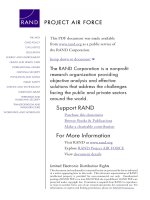
Figure 4 shows a simple MSC with five processes (vertical lines). It is in fact
drawn from our DEBIE case study, which models the controller for a space debris
management system. The five processes are mapped on to four cores. Each
process is mapped to a unique core, but several processes may be mapped to
the same core (e.g., Health-monitoring and Telecommand processes are mapped
to core 2 in Figure 4). Each process executes a sequence of “tasks” shown via
shaded rectangles (e.g., main1 , hm, tc are tasks in Figure 4). Each task is an
arbitrary (but terminating) sequential program in our setting and we assume
there is no code sharing across the tasks.
Semantically, an MSC denotes a set of tasks and prescribes a partial order
over these tasks. This partial order is the transitive closure of (a) the total order
of the tasks in each process (time flows from top to bottom in each process),
and (b) the ordering imposed by the send-receive of each message (the send of
a message must happen before its receive). Thus in Figure 4, the tasks in the
Main process execute in the sequence main1 , main2 , main3 , main4 . Also, due
to message send-receive ordering, the task main1 happens before the task hm.
However, the partial ordering of the MSC allows tasks hm and tc to execute
concurrently.
We assume that our concurrent program is executed in a static priority-driven
non-preemptive fashion. Thus, each process in an MSC is assigned a unique static
priority. The priority of a task is the priority of the process it belongs to. If
more than one processes are mapped to a processor core, and there are several
tasks contending for execution on the core (such as the tasks hm and tc on core
9
2.3
Message Sequence Graph
2
BACKGROUND
2 in Figure 4), we choose the higher priority task for execution. However, once a
task starts execution, it is allowed to complete without preemption from higher
priority tasks.
2.3
Message Sequence Graph
A Message Sequence Graph (MSG) is a finite graph where each node is described
by an MSC. Multiple outgoing edges from a node in the MSG represent a choice,
so that exactly one of the destination charts will be executed in succession.
While an MSC describes a single scenario in the system execution, an MSG
describes the control flow between these scenarios, allowing us to form a complete
specification of the application.
To complete the description of MSG, we need to give a meaning to MSC
concatenation. That is, if M1 , M2 are nodes (denoting MSCs) in an MSG, what
is the meaning of the execution sequence M1 , M2 , M1 , M2 , . . .? We stipulate that
for a concatenation of two MSCs say M1 ◦M2 , all tasks in M1 must happen before
any task in M2 . In other words, it is as if the participating processes synchronize
or hand-shake at the end of an MSC. In MSC literature, it is popularly known
as synchronous concatenation [3].
2.4
DEBIE Case Study
Our case study consists of DEBIE-I DPU Software [7], an in-situ space debris
monitoring instrument developed by Space Systems Finland Ltd. The DEBIE
instrument utilizes up to four sensor units to detect particle impacts on the
spacecraft. As the system starts up, it performs resets based on the condition
that precedes the boot. After initializations, the system enters the Standby state,
where health monitoring functions and housekeeping checks are performed. It
may then go into the Acquisition mode, where each particle impact will trigger
a series of measurements, and the data are classified and logged for further
transmission to the ground station. In this mode too, the Health Monitoring
10
2
BACKGROUND
2.5
Message Sequence Graph
System architecture
Node 1: Boot
Main
1: Boot
power-up
boot
2: Power-up
Reset
soft/warm
boot
3: Warm
Reset
watchdog
boot
checksum
boot
4: Record
CS Failure
Node 2: Power-up Reset
5: Record
WD Failure
Main
Classification
6: Initializations
Node 3: Warm Reset
7: Standby
Main
Classification
8: Acquisition
Node 4: Record WD Failure
Node 5: Record CS Failure
Main
Main
Node 6: Initializations
Main
Health
Monitoring
Telecommand
Node 7: Standby
Acquisition
Hit Trigger
ISR
Health
Monitoring
Telecommand
SU
Interface
[Env]
Sensor Unit
Node 8: Acquisition
Health
Monitoring
Telecommand
Telemetry
Acquisition
Classification
Hit Trigger
ISR
SU
Interface
[Env]
Sensor Unit
Figure 5: A multi-core architecture with shared cache.
process continues to periodically monitor the health of the instrument and to
run housekeeping checks.
The MSG for the DEBIE case study (with different colors used to show the
mapping of the processes to different processor cores) is shown in Figure 5. This
MSG is acyclic. For MSGs with cycles, the number of times each cycle can be
executed needs to be bounded for worst-case response time analysis.
2.5
System architecture
The generic multi-core architecture we target here is quite representative of the
current generation multi-core systems as shown in Figure 6. Each core on chip
has its own private L1 instruction cache and a shared L2 cache that accommodates instructions from all the cores. In this work, our focus is on instruction
11
2.5
System architecture
2
BACKGROUND
memory accesses and we do not model the data cache. We assume that the data
memory references do not interfere in any way with the L1 and L2 instruction
caches modeled by us (they could be serviced from a separate data cache that
we do not model).
Core 1
CPU
Core n
……
L1 Cache
CPU
L1 Cache
L2 Cache
Figure 6: A multi-core architecture with shared cache.
12
3
3
LITERATURE REVIEW
Literature Review
There have been a lot of research efforts in modeling cache behavior for WCET
estimation in single-core systems. A widely adopted technique is the abstract interpretation ([2, 24]) which also forms the foundation to the framework presented
in this thesis.
Mueller [15] extends the technique for multi-level cache analysis; Hardy and
Puaut [8] further adjust the method with a crucial observation to produce safe
estimates for set-associative caches. Other proposed methods that attempt exact classification of memory accesses for private caches include data-flow analysis [15], integer linear programming [12] and symbolic execution [13].
Cache analysis for multi-tasking systems mostly revolves around a metric
called cache-related preempted delay (CRPD), which quantifies the impact of
cache sharing on the execution time of tasks in a preemptive environment. CRPD
analysis typically computes cache access footprint of both the preempted and
preempting tasks ([10, 25, 16]). The intersection then determines cache misses
incurred by the preempted task upon resuming execution due to conflict in the
cache. Multiple process activations and preemption scenarios can be taken into
account, as in [21]. A different perspective in [23] considers WCRT analysis
for customized cache, specifically the prioritized cache, which reduces inter-task
cache interference.
In multiprocessing systems, tasks in different cores may execute in parallel while sharing memory space in the cache hierarchy. Due to the complexity involved in static analysis of multiprocessors, time-critical systems often
opt not to exploit multiprocessing, while non-critical systems generally utilize
measurement-based performance analysis. Tools for estimating cache access time
are presented, among others, in [19], [6] and [11]. It has also been proposed to
perform static scheduling of memory accesses so that they can be factored in to
achieve reliable WCET analysis on multiprocessors [18].
The only technique in literature that has addressed inter-core shared-cache
13
3
LITERATURE REVIEW
analysis so far is the one proposed by Yan and Zhang [26]. Their approach accounts for inter-core cache contention by detecting accesses across cores which
map to the same set in the shared cache. They treat all tasks executing in
a different core than the one under consideration as potential conflicts regardless of their actual execution time frames; thus the resulting estimate is highly
pessimistic. We also note that their work has not addressed the problem with
multi-level cache analysis observed by [8] (a “non-classified” access in L1 cache
cannot be safely assumed to always access L2 cache in the worst case) and will be
prone to unsafe estimation when applied to set-associative caches. This concern,
however, is orthogonal to the issues arising from cache sharing. Our proposed
analysis is able to obtain improved estimates by exploiting the knowledge about
interaction among tasks in the multiprocessor.
14
4
4
CONTRIBUTIONS
Contributions
Based on the literature review presented, our contributions in the thesis are as
following.
• The first contribution we make in this thesis is that we take into account the
execution interval of tasks to minimize the overestimation of interferences
in the shared cache between pairs of tasks from different cores and we
validate our estimation with experiments. We compare our method with
the only approach [26] in literature. And the only approach to model the
conflicts for L2 cache blocks among the cores is the following. Let T be
the task running on core 1 and T be the task running on core 2. Also
let M1 , . . . , MX (M1 , . . . , MY ) be the set of memory blocks of thread T
(T ) mapped to a particular cache set C in the shared L2 cache. Then
we simply deduce that all the accesses to memory blocks M1 , . . . , MX and
M1 , . . . , MY will be misses in L2 cache. However, we observed that if a pair
of tasks from different cores cannot overlap in terms of execution interval,
they are not able to affect each other in terms of conflict misses and thus
we can reduce the number of estimated conflict misses in the shared cache.
• Another contribution in this thesis is that we embrace set-associative caches
in our analysis as opposed to only direct mapped caches and this creates
additional opportunities for improving the timing estimation. For simplicity, direct-mapped cache is often assumed to be adopted. However, this
assumption is not practical since set-associative cache is prevalent.
In summary, we develop a timing analysis method for shared cache multicores that enhances the state-of-the-art approach.
15
5
5
5.1
APPROACH
Approach
Overview
In this section, we present an overview of our timing analysis framework for
concurrent applications running on a multi-core architecture with shared caches.
For ease of illustration, we will throughout use the example of a 2-core architecture. However, our method is easily scalable to any number of cores as will be
shown in the experimental evaluation. As we are analyzing a concurrent application, our goal is to estimate the Worst Case Response Time (WCRT) of the
application.
L1 cache
analysis
L1 cache
analysis
Core 1
Core 2
Filter
Filter
L2 cache
analysis
L2 cache
analysis
Initial task
interference
Estimated
WCRT
L2 cache
Conflict
analysis
Modified task
interference
WCRT
analysis
yes
no
Interference
changes?
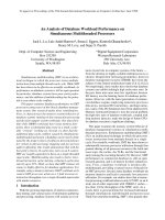
Figure 7: Our Analysis Framework
Figure 7 shows the workflow of our timing analysis framework. First, we
perform the L1 cache hit/miss analysis for each task mapped to each core independently. As we assume a non-preemptive system, we can safely analyze the
cache effect of each task separately even if multiple tasks are mapped to the
same processor core. For preemptive systems, we need to include cache-related
16
5
APPROACH
5.1
Overview
preemption delay analysis ([10, 25, 16, 21]) in our framework.
The filter at each core ensures that only the memory accesses that miss in
the L1 cache are analyzed at the L2 cache level. Again, we first analyze the L2
cache behavior for each task in each core independently assuming that there is no
conflict from the tasks in the other cores. Clearly, this part of the analysis does
not model any multi-core aspects and we do not propose any new innovations
here. Indeed, we employ the multi-level non-inclusive instruction cache modeling
proposed recently [8] for intra-core analysis.
The main challenge in safe and accurate execution time analysis of a concurrent application is the detection of conflicts for shared resources. In our
target platform, we are modeling one such shared resource: the L2 cache. A first
approach to model the conflicts for L2 cache blocks among the cores is the following. Let T be the task running on core 1 and T be the task running on core
2. Also let M1 , . . . , MX (M1 , . . . , MY ) be the set of memory blocks of thread T
(T ) mapped to a particular cache set C in the shared L2 cache. Then we simply
deduce that all the accesses to memory blocks M1 , . . . , MX and M1 , . . . , MY will
be misses in L2 cache. Indeed, this is the approach followed by the only shared
L2 cache analysis proposed in the literature [26].
A closer look reveals that there are multiple opportunities to improve the
conflict analysis. The first and foremost is to estimate and exploit the lifetime
information for each task in the system, which will be discussed in detail in the
following. If the lifetimes of the tasks T and T (mapped to core 1 and core
2, respectively) are completely disjoint, then they cannot replace each other’s
memory blocks in the shared cache. In other words, we can completely bypass
shared cache conflict analysis among such tasks.
The difficulty lies in identifying the tasks with disjoint lifetimes. It is easy to
recognize that the partial order prescribed by our MSC model of the concurrent
application automatically implies disjoint lifetimes for some tasks. However, accurate timing analysis demands us to look beyond this partial order and identify
additional pairs of tasks that can potentially execute concurrently according to
17
5.1
Overview
5
APPROACH
the partial order, but whose lifetimes do not overlap (see Section 5.2 for an example). Towards this end, we estimate a conservative lifetime for each task by
exploiting the Best Case Execution Time (BCET) and Worst Case Execution
Time (WCET) of each task along with the structure of the MSC model. Still the
problem is not solved as the task lifetime (i.e., BCET and WCET estimation)
depends on the L2 cache access times of the memory references. To overcome this
cyclic dependency between the task lifetime analysis and the conflict analysis for
shared L2 cache, we propose an iterative solution.
The first step of this iterative process is the conflict analysis. This step
estimates the additional cache misses incurred in the L2 cache due to intercore conflicts. In the first iteration, conflict analysis assumes very preliminary
task interference information — all the tasks (except those excluded by MSC
partial order) that can potentially execute concurrently will indeed execute concurrently. However, from the second iteration onwards, it refines the conflicts
based on task lifetime estimation obtained as a by-product of WCRT analysis
component. Given the memory access times from both L1 and L2 caches, WCRT
analysis first computes the execution time bounds of every task, represented as
a range. These values are used to compute the total response time of all the
tasks considering dependencies. The WCRT analysis also infers the interference
relations among tasks: tasks with disjoint execution intervals are known to be
non-interfering, and it can be guaranteed that their memory references will not
conflict in the shared cache. If the task interference has changed from the previous iteration, the modified task interference information is presented to the
conflict analysis component for another round of analysis. Otherwise, the iterative analysis terminates and returns the WCRT estimate. Note the feedback
loop in Figure 7 that allows us to improve the lifetime bounds with each iteration
of the analysis.
18