IC implementation of a bioelectric acquisition system for medical application
Bạn đang xem bản rút gọn của tài liệu. Xem và tải ngay bản đầy đủ của tài liệu tại đây (3.17 MB, 135 trang )
IC IMPLEMENTATION OF A
BIOELECTRIC ACQUISITION SYSTEM
FOR MEDICAL APPLICATION
HONG JYE SHENG
(B.Eng (Hons), NUS)
A THESIS SUBMITTED
FOR THE DEGREE OF MASTER OF ENGINEERING
DEPARTMENT OF ELECTRICAL & COMPUTER ENGINEERING
NATIONAL UNIVERSITY OF SINGAPORE
2005
ACKNOWLEDGEMENTS
I would like to express my gratitude towards my supervisor, Asso. Prof Lian
Yong and Asso. Prof Kenneth Ong Kok Wee for the invaluable guidance over my
Master’s research project. Special thanks to my immediate project supervisor, Asso.
Prof Lian Yong, for giving me precious opinions and help as well as the provision of
information on the necessary reference books and documents without which the
research project could not be completed successfully.
Next, I would also like to thank my colleagues from the Signal Processing and
VLSI Design Laboratory namely, Yu Rui, Chen Jiang Zhong, Wu Hong Lei and Gu
Jun for their help during my circuit design process as well during my IC chip testing
process. Special thanks also go out to the lab officer Zheng Huan Qun for her help in
solving cadence software related problems.
Next, I would also like to thank especially my parents for their moral support
and encouragement that they gave me especially in difficult times without which this
project might not have been completed successfully.
Last but not least, I would like to thanks all my friends and all personnel who
have help me in one way or another throughout the duration of this project.
i
CONTENTS
ACKNOWLEDGEMENTS
i
SUMMARY
v
LIST OF FIGURES
vii
LIST OF TABLES
xii
LIST OF SYMBOLS AND ABBREVIATIONS
xiii
Chapter 1
Introduction
1.1
Background
1
1.2
Literature Overview and Proposed Method
4
1.3
Thesis Organization
7
Chapter 2
Test and Evaluation of the Initial Fabricated IC
2.1
Introduction
9
2.2
Brief Description of the Initial Design
9
2.3
Printed Circuit Board Design
11
2.4
Test and Evaluation of the Instrumentation Amplifier
13
2.5
Test and Evaluation of the Low Pass Filter
15
2.6
Test and Evaluation of the Analog-to-Digital Converter
17
2.7
Electrocardiogram (ECG) Signal Acquisition Test
20
2.8
Conclusion from the Test & Evaluation of the Fabricated IC 22
Chapter 3
Design of a the Instrumentation Amplifier
3.1
Introduction
24
3.2
Design of the Instrumentation Amplifier
25
ii
3.2.1 Chopper Amplifier
26
3.2.2 Residue Offset in Chopper Amplifier
28
3.2.3 Nested Chopper Instrumentation Amplifier
29
3.3
Circuit Design of the Nested Chopper IA
31
3.4
Common Mode Voltage Interference
34
3.4.1 Driven-Right-Leg (DRL) Circuit
36
3.5
Overall Circuit Diagram of the Instrumentation Amplifier
37
3.6
Conclusion
38
Chapter 4
Design of the Low Pass Filter
4.1
Introduction
39
4.2
Design of a 6th Order Butterworth Filter using SC Method
40
4.3
Design of the Two Stage Operational Amplifier
45
4.4
Design of the MOS Switches
46
4.5
Design of the Two Phase Non-Overlapping Clock
51
4.6
Design of the Fleischer Laker Active SC Biquad
52
4.7
Conclusion
56
Chapter 5
Design of the Analog-to-Digital Converter
5.1
Introduction
57
5.2
Working Principle of a Successive Approximation ADC
58
5.3
Design of the Successive-Approximation-Register
62
5.3.1 SAR counter
62
5.3.2 SAR logic
63
Design of the Comparator
65
5.4
iii
5.5
Design of the Clocks and Control Signal Generator
67
5.6
Design of the Capacitor Array
71
5.7
Conclusion
72
Chapter 6
Schematic Implementation, Layout and Post Layout
Simulation
6.1
Introduction
6.2
Implementation and Simulation of the Instrumentation Amp 73
6.3
6.4
73
6.2.1 Chopper Amplifier
74
6.2.2 Nested Chopper Amplifier
76
Implementation and Simulation of the Low Pass Filter
85
6.3.1 Two Stage Operational Amplifier
85
6.3.2 Sixth Order Switched Capacitor Low Pass Filter
88
Implementation and Simulation of the ADC
93
6.4.1 Regenerative Comparator
93
6.4.2 12 bit Successive Approximation ADC
96
6.5
Chip Layout
102
6.6
Conclusion
103
Chapter 7
Conclusion
7.1
Conclusion
104
7.2
Problems Encountered
105
7.3
Proposed Future Works
106
REFERENCES
107
APPENDIX
109
iv
SUMMARY
In this thesis, a bioelectric acquisition system which consists of an
instrumentation amplifier (IA), a low pass filter (LPF) and an analog-to-digital
converter (ADC) was design using the Cadence circuit design tool. The system was
design specifically for ECG signal acquisition. In the implementation of the
instrumentation amplifier, the nested-chopper architecture was use to help reduce the
1/f flicker noise which is significant especially at low frequency. In addition, a
driven-right-leg circuit and a DC suppression circuit was also included in the final
amplifier circuit to help remove common mode interference originating from nearby
power sources and baseline DC drift due to patient’s movement.
In the implementation of the low pass filter, a sixth order 125Hz low pass was
implemented using the switched capacitor (SC) method. Three Fleischer Laker Active
SC Biquads, cascaded together, were used for the implementation of this filter. As the
capacitors used in the implementation of switched capacitor filters take up a lot of the
precious silicon area, an algorithm is presented to minimize the total capacitance used.
This was done by an analytical study of the transfer function of the Fleischer Laker
Active SC Biquad in order to optimize the capacitor assignment followed by employing
a T-network structure to minimize the capacitance spread.
As for the ADC, a 12-bit successive approximation analog-to-digital converter
(SAR ADC) was implemented. A capacitive DAC was use to eliminate the need of a
sample and hold circuit. By using a novel yet simple algorithm, the total capacitance
usage is further reduced by half.
v
Numerous post layout simulations were conducted on the circuits implemented
and the results for all three portion shows promising results. The instrumentation
amplifier has a total integrated input referred noise (0.1Hz to 125Hz) of as low as
6.4949µV whereas the low pass filter simulated is highly accurate and have an
attenuation of 44.74dB from passband edge at 125Hz to stopband edge at 300Hz. The
ADC on the hand was also simulated to be highly accurate with the maximum error
across the entire input voltage range being as low as 1 LSB.
Lastly, test and evaluation of an earlier version of the integrated chip also
shows promising results. Test conducted in the acquisition of the ECG signals shows
that important points on the ECG signal can be acquired using the fabricated chip.
vi
LIST OF FIGURES
Figure 1.1
Overview of the bioelectric acquisition system
1
Figure 1.2
Bioelectric acquisition system for ECG signal acquisition
5
Figure 2.1
Initial Design of the Instrumentation Amplifier
10
Figure 2.2
Initial Design of the Low Pass Filter
10
Figure 2.3
Initial Design of the Analog-to-Digital Converter
11
Figure 2.4
PCB Design used for chip testing
12
Figure 2.5
Phase (top left) and magnitude (bottom left) response of the IA
13
Figure 2.6
Input referred noise of the instrumentation amplifier
14
Figure 2.7
Phase (top) and magnitude (bottom) response of a second
15
order LPF
Figure 2.8
Phase (top) and magnitude (bottom) response of a sixth
16
order LPF
Figure 2.9
Output voltage of the analog-to-digital converter (left) and the
17
calculated output voltage error (right)
Figure 2.10
Histogram showing the distribution of the digital output code
18
Figure 2.11
Differential Non Linearity (DNL) of the ADC
19
Figure 2.12
A typical ECG signal
20
Figure 2.13
ECG signal output obtained from the output of the
21
instrumentation amplifier
Figure 2.14
ECG signal output obtained after passing through the LPF
21
vii
Figure 3.1
(a) Basic differential amplifier structure and (b) buffered
25
differential amplifier used to implement the IA
Figure 3.2
Chopper amplifier and chopping principle in the frequency domain 26
Figure 3.3
Noise power spectrum of chopper amplifier
27
Figure 3.4
Residue offset caused by spikes upon demodulation
28
Figure 3.5
Residual offset using nested-chopper instrumentation amplifier
29
Figure 3.6
Buffered differential amplifier with nested-choppers
30
Figure 3.7
Schematic diagram of the chopper amplifier
31
Figure 3.8
Common-mode feedback circuit where Q1, Q2, Q3 and Q4
33
are identical
Figure 3.9
Model for two bioelectric signal recording
35
Figure 3.10
Model for three electrode bioelectric signal recording with
36
a driven-right-leg circuit
Figure 3.11
Final circuit diagram of the entire instrumentation amplifier
37
Figure 4.1
Anti-aliasing filter characteristic
39
Figure 4.2
Relationship between the continuous time domain and the
42
sampled domain
Figure 4.3
The schematic for a general parasitic insensitive active-SC biquad 44
Figure 4.4
Schematic diagram of a two stage operational amplifier
45
Figure 4.5
A resistor capacitor equivalent model of a MOSFET switch
49
Figure 4.6
(a) Transition of gate voltage in a transmission gate.
50
(b) Charge compensation when t >tn
Figure 4.7
Circuit implementation of a two phase non-overlapping clock
51
viii
Figure 4.8
Implementation of a (a)normal and a(b)T-network integrator
53
Figure 5.1
Successive approximation architecture base on charge
58
redistribution
Figure 5.2
Sample-and-hold function of the capacitor array
59
Figure 5.3
Change in the common terminal voltage for a 2 bit computation
60
Figure 5.4
Digital output derivation for a 4 bit ADC
61
Figure 5.5
Synchronous 5-bit counter
62
Figure 5.6
5-24 bit decoder
63
Figure 5.7
SAR Logic for the second MSB
64
Figure 5.8
Schematic diagram of a regenerative comparator
65
Figure 5.9
Voltage waveform of VA, VB and Vout for different input condition 66
Figure 5.10
Clock signals generator
67
Figure 5.11
Clock signals waveform
68
Figure 5.12
Delays generator
69
Figure 5.13
Logic control block
70
Figure 5.14
Control signals waveform
70
Figure 5.15
Capacitor array switch
71
Figure 6.1
Schematic diagram of the chopper amplifier
74
Figure 6.2
Mask layout of the chopper amplifier
75
Figure 6.3
Magnitude and phase response of the chopper amplifier
76
Figure 6.4
Input referred (left) noise and total output noise (right) of
77
the amplifier with (red) and without (black) chopper
Figure 6.5
Schematic diagram of the nested chopper instrumentation
78
ix
amplifier
Figure 6.6
Floor plan and mask layout of the nested chopper
79
instrumentation amplifier
Figure 6.7
Magnitude response of the nested chopper instrumentation
80
amplifier
Figure 6.8
Input referred (left) noise and total output noise (right) of the
81
amplifier with (red) and without (black) chopper
Figure 6.9
Input signal transient response and the DFT spectrum
82
Figure 6.10
Transient response and DFT spectrum after the first chopper
83
(bottom) and after the chopper amplifier (top)
Figure 6.11
Transient response and DFT spectrum of the output voltage
84
before (bottom) and after the low pass filter (top)
Figure 6.12
Schematic diagram of the two stage operational amplifier
85
Figure 6.13
Mask layout the two stage operational amplifier
86
Figure 6.14
Magnitude and phase response of the two stage operational
87
Amplifier
Figure 6.15
Schematic diagram of the Fleischer Laker SC Biquad
88
Figure 6.16
Schematic diagram of the 6th order SC low pass filter
89
Figure 6.17
Mask layout of the 6th order SC low pass filter
89
Figure 6.18
Magnitude response of the 6th order low pass filter
90
Figure 6.19
Transient output for the low pass filter for a 1mV, 80Hz
91
input signal
Figure 6.20
Clock feedthrough on the transient output for a 1mV, 80Hz
91
x
input signal
Figure 6.21
Transient output for the low pass filter for a 300mV, 80Hz
92
input signal
Figure 6.22
Schematic diagram of the regenerative comparator
93
Figure 6.23
Mask layout of the regenerative comparator
94
Figure 6.24
Transient response of the regenerative comparator
95
Figure 6.25
Schematic diagram of the digital block in the ADC
96
Figure 6.26
Schematic diagram of the analog block in the ADC
97
Figure 6.27
Schematic diagram of the 12bit successive approximation ADC
97
Figure 6.28
Mask layout of the 12bit successive approximation ADC
98
Figure 6.29
Transient response of the outputs from the digital block of the ADC 99
Figure 6.30
Chip layout
100
xi
LIST OF TABLES
Table 1.1
Voltage and Frequency ranges for some important parameters
3
measured in the human body
Table 1.2
Specification of individual building blocks of the ECG
6
bioelectric acquisition system
Table 2.1
Component used for chip testing and evaluation
12
Table 2.2:
Suggested improvements from the initial design
23
Table 4.1
Capacitor values for all 3 stages of biquad
42
Table 4.2
Capacitor Values Assignment using conventional method and the 52
capacitor optimization method (Stage 1)
Table 4.3
Capacitor Values Assignment using conventional method and the 53
capacitor optimization method (Stage 2)
Table 4.4
Capacitor Values Assignment using conventional method and the 53
capacitor optimization method (Stage3)
Table 6.1
Specification overview of the chopper amplifier
75
Table 6.2
Specification overview of the nested chopper instrumentation
82
Amplifier
Table 6.3
Specification overview of the two stage operational amplifier
85
Table 6.4
Specification overview of the 6th order SC LPF
90
Table 6.5
Specification overview of the regenerative comparator
93
Table 6.6
Simulation results of the ADC
98
Table 6.7
Specification overview of the SAR ADC
99
xii
LIST OF SYMBOLS AND ABBREVIATIONS
Resistor
Capacitor
or
Circuit Common / Analog Ground
Earth Ground
Operational Amplifier
Comparator
Instrumentation Amplifier
Current Source
Voltage Source
P-mos
or
xiii
N-mos
or
Switch
Multiplexor
Chopper
NOT gate
AND gate
NOR gate
NAND gate
NOR gate
xiv
J K Flip-flop
T Flip-flop
D Latch
D Flip-flop
xv
Chapter 1: Introduction
CHAPTER 1
INTRODUCTION
1.1 Background
In recent years, in search of methods that are both fast and accurate in diagnosing a
patient, a particular challenge has arisen in noninvasive medical diagnostic
procedures. Because biosignals recorded on the body surface reflect the internal
behavior and the status of particular body organs, they are ideally suited to provide
essential information of these organs to the clinician without any invasive measures.
Before these signals could be studied and analyze, a bioelectric signal acquisition
system is required to translate these biosignals into useful electric signals which can
then be processed, displayed and stored on electronic devices.
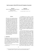
Figure 1.1: Overview of the bioelectric acquisition system
The bioelectric signal acquisition system for medical application usually
consists of the transducer, followed by an instrumentation amplifier (IA) and a low
pass filter (LPF) in the analog preprocessing block, and end with an analog-to-digital
1
Chapter 1: Introduction
converter (ADC) as is illustrated in the Figure 1.1. This whole system serves to
collect the analog bioelectric signal generated by the human body such as the
electrocardiogram (ECG) signal and the electroencephalogram (EEG) signal and
convert them into digital signals. By doing so, the data can easily be stored and
processed later using computers or be transmitted out to remote receiver using digital
communication methods. However as these measuring instruments are commonly
subjected to high frequency noises originated either from radio broadcast or cellular
phones and low frequency artifacts from human himself, the analog preprocessing
blocks must have a high performance over the required frequency range to ensure
good filtering before the bioelectric signals are being processed.
There are various types of bioelectric signals that are used for medical
applications and a few major bioelectric signals are shown in Table 1.1. As seen
from the table, these signals typically are in the range of 1µV-25mV while the
frequencies are usually in the range of a few hertz to a few hundred hertz. With their
low magnitude and low frequency characteristics, these bioelectric signals collected
are commonly subjected to flicker noise (1/f) which could easily overwhelm the
bioelectric signals particularly at very low frequencies.
Therefore, in the
implementation of the instrumentation amplifier, the design of a low noise circuit
with a large signal-to-noise ratio (SNR) is very crucial.
2
Chapter 1: Introduction
Parameter
Sensor Location
Voltage
Frequency
range
Range
Electrocardiography (ECG)
skin electrodes
0.1 ~ 25mV
0.1-125
Electroencephalogram (EEG)
scalp electrodes
5 ~ 200µV
DC - 60
Electrogastrography (EGG)
stomach-surface
0.5 ~ 80 mV
DC - 1
electrodes
Electrooculography (EOG)
contact electrode
50 ~ 3500µV
DC - 50
Electroretinography (ERG)
contact electrode
0 ~ 900µV
DC - 50
Table 1.1: Voltage and Frequency ranges for some important parameters measured
in the human body
From Table 1.1, we can also see that the low-pass filter which serves to
adjust the frequency band according to the required bioelectric input signals have to
have a low cutoff frequency (<125Hz). This result in a large time constant needed for
the implementation of the low pass filter which leads to the need for large size
capacitors. For practical capacitor implementation, silicon area requirement usually
limits its size and can be no larger than 50pF. In addition to a low cutoff frequency, a
sharp attenuation LPF is also required to remove aliasing noises before it is
converted to digital signals.
Lastly, as even a small deviation of the bioelectric signals is important in the
diagnosis of a patient; an accurate analog-to-digital converter is required so that the
output waveform display on the monitor screens is in the exact form as the original
bioelectric signal. Even with a pre-amplification from the instrumentation amplifier,
an analog-to-digital converter with a resolution of 10-12bits is still required.
3
Chapter 1: Introduction
1.2 Literature Overview and Proposed Method
Several design techniques have already been proposed for the implementation of
such bioelectric acquisition system [1], [2]. In these papers, high resolution
acquisition systems were designed using multiple chips combined into an
embedded system on a printed circuit board (PCB). As the result, these systems are
more bulky and not suitable to be a very portable device where the users can wear
the system while conducting daily activities without being constrained.
An effort to combine these systems into a single chip solution was shown
by Lasanen and Kostamovaara [3]. In their system, they have employed an offsetcompensated preamplifier and a 8th order Butterworth switched-opamp, switched
capacitor filter to realize a circuit that can operate at a very low supply voltage of
1V-1.8V. A similar system was proposed by C.J Yen [4] where he concentrated on
critical issues relating to the design of a high performance analog preprocessor
which includes offset minimization, noise performance, power consumption and
process-dependent limitation. However, in both these systems, an analog-to-digital
conversion was implemented separately.
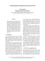
In this project, a bioelectric signal acquisition system, specifically for ECG
signal acquisition, consisting of the instrumentation amplifier, the low pass filter
and the ADC will be implemented on a single chip as shown in Figure 1.2. This not
only help to increase the overall performance compared to the implementation on
PCB level but can also help remove repetitive components which will be reveal
later in the report. Upon conversion of the ECG signal, the digital data will be fed
into a microprocessor for analyzing and storage purposes.
4
Chapter 1: Introduction
Figure 1.2: Bioelectric acquisition system for ECG signal acquisition
In the implementation of the instrumentation amplifier, the nested chopper
architecture was used to remove the 1/f flicker noise. A driven-right-leg circuit and
a DC suppression circuits which function to remove common mode interference
and baseline drift are also added into the final instrumentation amplifier to
eliminate the need for external circuits during the actual signal acquisition process.
In the implementation of the low pass filter, a 125Hz Butterworth low pass
filter was implemented using the switched capacitor (SC). The motivation behind
using the switched capacitor technique is due to the good accuracy and its ability to
implement large resistors using small capacitor through the resistor approximation
technique. To further reduce the total capacitance in the circuit, a capacitor
optimization method and a T-network structure was proposed which help save
precious silicon area by obtaining the minimum possible capacitor value needed and
by reducing the total capacitance spread.
Lastly, a 12-bit successive approximation analog-to-digital converter was
implemented for the data conversion process. The structure was chosen ahead of
other structures such as the flash converter and dual slope integrating converter for
its high accuracy and low power consumption characteristics. In addition, a novel
5
Chapter 1: Introduction
implementation method was also introduced which will help reduce the total
capacitance required by half.
Table 1.2 shows a summary of the intended specification for the individual
building blocks used to implement the final bioelectric acquisition system
specifically for ECG signal.
Instrumentation
Main Specifications
Description
Unit
- Low Noise and Interference
> 40dB SNR (Vn<10 µV)
Amplifier (IA)
- Low Power Consumption
< 3mW ( I <1mA)
- Programmable gain
Low Pass Filter
- Accurate cutoff frequency
125Hz
(LPF)
- High attenuation at 300Hz
> 40dB attenuation
- Low power consumption
<1mW (I <333µA)
- Low passband distortion
Analog-to-Digital
- High conversion accuracy
>10 bit accuracy
Converter (ADC)
- Low Power Consumption
<1mW (I <333µA)
Table 1.2: Specification of individual building blocks of the ECG bioelectric
acquisition system
6
Chapter 1: Introduction
1.3 Thesis Organization
During the course of this project, two separate designs of the bioelectric acquisition
system were actually implemented. The first design, which was a simpler design,
was aimed towards testing the general functionality of the whole system. The
design was fabricated in the middle of this project and the results served to provide
a good insight of the potential problems that may have been overlooked through
simulations alone. Based on the results that were obtained through the evaluation of
the fabricated chip, improvements were made to each building block to come out
with the final bioelectric acquisition system design.
Therefore, in the following chapter, Chapter 2, the test and evaluation of
the initial fabricated chip is first presented. And base on the insights that were
attained through the evaluation of the fabricated chip, possible improvements were
suggested to be implemented. The final implementation and the overall architecture
of the each building block in the bioelectric acquisition system, namely the
instrumentation amplifier the low pass filter and the analog-to-digital converter will
then be explained in detail in Chapter 3, Chapter 4 and Chapter 5 respectively.
In each of these chapters, potential problems that may affect the final performance
of each building block will also be discussed. This will be followed by precautions
taken to solve or to minimize their effects.
In Chapter 6, the final schematic design and the mask layout drawn will be
presented. This will give an insight of the final die size required for the actual
implementation of the whole bioelectric acquisition system. To show its final
performance, post layout simulations of each building block, which includes all the
7
Chapter 1: Introduction
parasitic capacitance, will be presented. This will give a good insight of the final
performance of the implemented system.
Lastly, in Chapter 7, the conclusion of the project is presented to
summarize the achievements obtained. A brief discussion of the problems
encountered together with the proposed future works will also be included.
8
Chapter 2: Test and Evaluation of the Initial Fabricated IC
CHAPTER 2
TEST AND EVALUATION OF THE INITIAL FABRICATED IC
2.1 Introduction
An earlier version of the bioelectric acquisition system was sent for fabrication. In
this version, the instrumentation amplifier was constructed using a simple three opamp structure. This structure serves to amplify the voltage difference between only
two electrodes and the gain of this instrumentation amplifier is varied by changing a
single external resistor. This was followed by a 6th order switched capacitor low pass
filter which was implemented by cascading three second order Fleischer Laker
Active-SC Biquad. For the analog-to-digital converter (ADC), a 12 bit successive
approximation analog-to-digital converter was implemented. The main purpose of
this fabrication was first to confirm the general functionality of the initial design. In
addition, it also serves to obtain an insight of any potential problems that may be
overlooked through simulation alone. With this information in mind, the final design
will not only be aimed towards providing a working acquisition system but will also
aim towards solving each of these problems.
2.2 Brief Description of the Initial Design
As mentioned earlier, the initial instrumentation amplifier was implemented using
the basic three op-amp structure as shown in Figure 2.1. The first two op-amps serve
as the buffered gain stage where the gain is varied by adjusting the value of a single
9