Wireless Optical Communication Systems Springer Verlag Telos
Bạn đang xem bản rút gọn của tài liệu. Xem và tải ngay bản đầy đủ của tài liệu tại đây (6.98 MB, 210 trang )
Wireless Optical
Communication Systems
This page intentionally left blank
WIRELESS OPTICAL
COMMUNICATION SYSTEMS
STEVE HRANILOVIC
Assistant Professor
Department of Electrical and Computer Engineering
McMaster University
Hamilton‚ Ontario‚ Canada
Springer
eBook ISBN:
Print ISBN:
0-387-22785-7
0-387-22784-9
©2005 Springer Science + Business Media, Inc.
Print ©2005 Springer Science + Business Media, Inc.
Boston
All rights reserved
No part of this eBook may be reproduced or transmitted in any form or by any means, electronic,
mechanical, recording, or otherwise, without written consent from the Publisher
Created in the United States of America
Visit Springer's eBookstore at:
and the Springer Global Website Online at:
To Annmarie
This page intentionally left blank
Contents
Dedication
Preface
v
xi
Part I Introduction
1. INTRODUCTION
1.1 A Brief History of Wireless Optical Communications
1.2
Overview
3
5
7
2. WIRELESS OPTICAL INTENSITY CHANNELS
2.1 Wireless Optical Intensity Channels
2.2 Optoelectronic Components
2.3 Noise
2.4 Channel Topologies
2.5 Summary
9
10
16
27
31
35
3. AN INTRODUCTION TO OPTICAL INTENSITY SIGNALLING
3.1 Communication System Model
3.2 Bandwidth
3.3 Example Modulation
3.4 The Communication System Design Problem
39
39
47
51
64
viii
WIRELESS OPTICAL COMMUNICATION SYSTEMS
Part II
Signalling Design
4. OPTICAL INTENSITY SIGNAL SPACE MODEL
4.1 Signal Space of Optical Intensity Signals
4.2 Examples
4.3 Conclusions
69
69
77
81
5. LATTICE CODES
5.1 Definition of Lattice Codes
5.2 Constellation Figure of Merit‚ Gain
83
84
86
5.3 Baseline Constellation
5.4 Spectral Considerations
5.5 Gain versus a Baseline Constellation
5.6 Continuous Approximation to Optical Power Gain
5.7 Coding Gain
5.8 Shaping Gain
5.9 Shaping Gain: Expression
5.10
5.11
5.12
5.13
5.A
Shaping Gain: Peak-Symmetric Schemes
Opportunistic Secondary Channels
Example Lattice Codes
Conclusions
Continuous Approximation of the Power Spectral Density
6. CHANNEL CAPACITY
6.1 Background
6.2 Problem Definition
6.3 BandwidthConstraint
6.4 Upper bound on Channel Capacity
6.5 Lower bound on Channel Capacity
6.6 Examples and Discussion
6.7 Conclusions
88
88
90
90
91
92
93
94
95
95
102
104
107
107
109
110
111
115
117
124
Contents
ix
Part III Multi-Element Techniques
7. THE MULTIPLE-INPUT / MULTIPLE-OUTPUT
WIRELESS OPTICAL CHANNEL
7.1 Previous Work
7.2 The MIMO Wireless Optical Channel
7.3 Design Challenges
7.4 Pixel-Matched System
7.5 The Pixelated Wireless Optical Channel
7.6 Conclusions
8. PROTOTYPE MIMO OPTICAL CHANNEL:
MODELLING & SPATIO-TEMPORAL CODING
8.1 Experimental Prototype
8.2 Channel Model
8.3 Pixel-Matched Systems
8.4 Pixelated Wireless Optical Channel
8.5 Conclusions
127
128
130
136
138
140
146
149
149
153
164
165
174
9. CONCLUSIONS AND FUTURE DIRECTIONS
9.1 Conclusions
9.2 Future Work
177
177
178
References
181
Index
195
About the Author
197
This page intentionally left blank
Preface
The use of optical free-space emissions to provide indoor wireless communications has been studied extensively since the pioneering work of Gfeller
and Bapst in 1979 [1]. These studies have been invariably interdisciplinary involving such far flung areas such as optics design‚ indoor propagation studies‚
electronics design‚ communications systems design among others. The focus
of this text is on the design of communications systems for indoor wireless
optical channels. Signalling techniques developed for wired fibre optic networks are seldom efficient since they do not consider the bandwidth restricted
nature of the wireless optical channel. Additionally‚ the elegant design methodologies developed for electrical channels are not directly applicable due to the
amplitude constraints of the optical intensity channel. This text is devoted to
presenting optical intensity signalling techniques which are spectrally efficient‚
i.e.‚ techniques which exploit careful pulse design or spatial degrees of freedom
to improve data rates on wireless optical channels.
The material presented here is complementary to both the comprehensive
work of Barry [2] and to the later book by Otte et al. [3] which focused primarily on the design of the optical and electronic sub-systems for indoor wireless
optical links. The signalling studies performed in these works focused primarily on the analysis of popular signalling techniques for optical intensity
channels and on the use of conventional electrical modulation techniques with
some minor modifications (e.g.‚ the addition of a bias). In this book‚ the design
of spectrally efficient signalling for wireless optical intensity channels is approached in a fundamental manner. The goal is to extend the wealth of modem
design practices from electrical channels to optical intensity domain. Here we
discuss important topics such as the vector representation of optical intensity
signals‚ the design and capacity of signalling sets as well as the use of multiple
transmitter and receiver elements to improve spectral efficiency.
Although this book is based on my doctoral [4] and Masters [5] theses‚ it
differs substantially from both in several ways. Chapters 2 and 3 are com-
xii
pletely re-written and expanded to include a more tutorial exposition of the
basic issues involved in signalling on wireless optical channels. Chapters 4-6‚
which develop the connection between electrical signalling design and optical intensity channels‚ are significantly re-written in more familiar language
to allow them to be more accessible. Chapters 7 and 8 are improved through
the addition of a fundamental analysis of MIMO optical channels and the increase in capacity which arise due to spatial multiplexing in the presence of
spatial bandwidth constraints. Significant background material has been added
on the physical aspects of wireless optical channels including optoelectronic
components and propagation characteristics to serve as an introduction to communications specialists. Additionally‚ fundamental communication concepts
are briefly reviewed in order to make the signalling design sections accessible
to experimentalists and applied practitioners.
Finally‚ there have been a great number of individuals who have influenced
the writing of this book and deserve my thanks. I am very grateful to my doctoral
thesis advisor Professor Frank R. Kschischang who’s passion for research and
discovery have inspired me. Additionally‚ I would like to thank Professors
David A. Johns and Khoman Phang for introducing me to the area and for
fostering my early explorations in wireless optical communications. I am also
indebted to a number of friends and colleagues who have contributed through
many useful conversations‚ among them are : Warren Gross‚ Yongyi Mao‚
Andrew Eckford‚ Sujit Sen‚ Tooraj Esmailian‚ Terence Chan‚ Masoud Ardakani
and Aaron Meyers.
Foremost‚ I would like to thank my wife Annmarie for her patience‚ understanding and for her support.
STEVE HRANILOVIC
PART I
INTRODUCTION
This page intentionally left blank
Chapter 1
INTRODUCTION
In recent years, there has been a migration of computing power from the
desktop to portable, mobile formats. Devices such as digital still and video
cameras, portable digital assistants and laptop computers offer users the ability
to process and capture vast quantities of data. Although convenient, the interchange of data between such devices remains a challenge due to their small size,
portability and low cost. High performance links are necessary to allow data
exchange from these portable devices to established computing infrastructure
such as backbone networks, data storage devices and user interface peripherals.
Also, the ability to form ad hoc networks between portable devices remains an
attractive application. The communication links required can be categorized as
short-range data interchange links and longer-range wireless networking applications.
One possible solution to the data interchange link is the use of a direct electrical connection between portable devices and a host. This electrical connection
is made via a cable and connectors on both ends or by some other direct connection method. The connectors can be expensive due to the small size of the
portable device. In addition, these connectors are prone to wear and break
with repeated use. The physical pin-out of the link is fixed and incompatibility
among various vendors solutions may exist. Also, the need to carry the physical
medium for communication makes this solution inconvenient for the user.
Wireless radio frequency (RF) solutions alleviate most of the disadvantages
of a fixed electrical connection. RF wireless solutions allow for indoor and short
distance links to be established without any physical connection. However,
these solutions remain relatively expensive and have low to medium data rates.
Some popular “low cost” RF links over distances of approximately 10m provide
data rates of up to 1 Mbps in the 2.4 GHz band for a cost near US$5 per
module. Indoor IEEE 802.11 [6] links have also gained significant popularity
4
Introduction
and provide data rates of approximately 50 Mbps. Radio frequency wireless
links require that spectrum licensing fees are paid to federal regulatory bodies
and that emissions are contained within strict spectral masks. These frequency
allocations are determined by local authorities and may vary from country
to country, making a standard interface difficult. In addition, the broadcast
nature of the RF channel allows for mobile connectivity but creates problems
with interference between devices communicating to a host in close proximity.
Containment of electromagnetic energy at RF frequencies is difficult and if
improperly done can impede system performance.
This book considers the use of wireless optical links as another solution to the
short-range interchange and longer-range networking links. Table 1.1 presents
a comparison of some features of RF and wireless optical links. Present day
wireless optical links can transmit at 4 Mbps over short distances using optoelectronic devices which cost approximately US$1 [7]. However, much high
rates approaching 1 Gpbs have been investigated in some experimental links.
Wireless optical links transmit information by employing an optoelectronic
light modulator, typically a light-emitting diode (LED). The task of up- and
down-conversion from baseband frequencies to transmission frequencies is accomplished without the use of high-frequency RF circuit design techniques, but
is accomplished with inexpensive LEDs and photodiodes. Since the electromagnetic spectrum is not licensed in the optical band, spectrum licensing fees
are avoided, further reducing system cost. Optical radiation in the infrared or
visible range is easily contained by opaque boundaries. As a result, interference
between adjacent devices can be minimized easily and economically. Although
this contributes to the security of wireless optical links and reduces interference
it also impacts rather stringently on the mobility of such devices. For example,
it is not possible for a wireless optical equipped personal digital assistant to
communicate if it is stored in a briefcase. Wireless optical links are also suited
to portable devices since small surface mount light emitting and light detecting
components are available in high volumes at relatively low cost.
A Brief History of Wireless Optical Communications
5
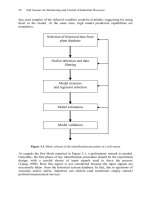
Figure 1.1. An indoor wireless optical communication system.
Figure 1.1 presents a diagram of a typical indoor wireless optical communications scenario. Mobile terminals are allowed to roam inside of a room and
require that links be established with a ceiling basestation as well as with other
mobile terminals. In some links the radiant optical power is directed toward the
receiver, while in others the transmitted signal is allowed to bounce diffusely
off surfaces in the room. Ambient light sources are the main source of noise
in the channel and must be considered in system design. However, the available bandwidth in some directed wireless optical links can be large and allows
for the transmission of large amounts of information, especially in short range
applications.
Indoor wireless optical communication systems are envisioned here as a
complimentary rather than a replacement technology to RF links. Whereas,
RF links allow for greater mobility wireless optical links excel at short-range,
high-speed communications such as in device interconnection or board-to-board
interconnect.
1.1
A Brief History of Wireless Optical Communications
The use of optical emissions to transmit information has been used since
antiquity. Homer, in the Iliad, discusses the use of optical signals to transmit
a message regarding the Grecian siege of Troy in approximately 1200 BC.
Fire beacons were lit between mountain tops in order to transmit the message
6
Introduction
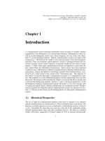
Figure 1.2. Drawing of the photophone by Alexander Graham Bell and Charles Sumner Tainter,
April 1880 [The Alexander Graham Bell Family Papers, Library of Congress].
over great distances. Although the communication system is able to only ever
transmit a single bit of information, this was by far the fastest means to transmit
information of important events over long distances.
In early 1790’s, Claude Chappe invented the optical telegraph which was
able to send messages over distances by changing the orientation of signalling
“arms” on a large tower. A code book of orientations of the signalling arms
was developed to encode letters of the alphabet, numerals, common words
and control signals. Messages could be sent over distances of hundreds of
kilometers in a matter of minutes [8].
One of the earliest wireless optical communication devices using electronic
detectors was the photophone invented by A. G. Bell and C. S. Tainter and
patented on December 14, 1880 (U.S. patent 235,496). Figure 1.2 presents a
drawing made by the inventors outlining their system. The system is designed
to transmit a operator’s voice over a distance by modulating reflected light from
the sun on a foil diaphragm. The receiver consisted of a selenium crystal which
converted the optical signal into an electrical current. With this setup, they were
able to transmit an audible signal a distance of 213 m [9].
The modern era of indoor wireless optical communications was initiated in
1979 by F.R. Gfeller and U. Bapst by suggesting the use of diffuse emissions
in the infrared band for indoor communications [1]. Since that time, much
work has been done in characterizing indoor channels, designing receiver and
transmitter optics and electronics, developing novel channel topologies as well
as in the area of communications system design. Throughout this book, previous
work on a wide range of topics in wireless optical system will be surveyed.
Overview
1.2
7
Overview
The study of wireless optical systems is multidisciplinary involving a wide
range of areas including: optical design, optoelectronics, electronics design,
channel modelling, communications and information theory, modulation and
equalization, wireless optical network architectures among many others.
This book focuses on the issues of signalling design and information theory
for wireless optical intensity channels. This book differs from Barry’s comprehensive work Wireless Infrared Communications [2] and the text by Otte
et al. Low-Power Wireless Infrared Communications by focusing exclusively
on the design of modulation and coding for single element and multi-element
wireless optical links. This work is complimentary and focuses on the design of signalling and communication algorithms for wireless optical intensity
channels.
The design of a communication algorithms for any channel first requires
knowledge of the channel characteristics. Chapter 2 overviews the basic operation of optoelectronic devices and the amplitude constraints that they introduce.
Eye and skin safety, channel propagation characteristics, noise and a variety of
channel topologies are described.
Most signalling techniques for wireless optical channels are adapted from
wired optical channels. Conventional signalling design for the electrical channel cannot be applied to the wireless optical intensity channel due to the channel
constraints. A majority of signalling schemes for optical intensity channels deal
with binary-level on-off keying or PPM. Although power efficient, their spectral efficiency is poor. Chapter 3 overviews basic concepts in communications
system design such as vector channel model, signal space, bandwidth as well
a presenting an analysis of some popular binary and multi-level modulation
schemes.
Part II of this book describes techniques for the design and analysis of spectrally efficient signalling techniques for wireless optical channels. This work
generalizes previous work in optical intensity channels in a number of important
ways. In Chapter 4, a signal space model is defined which represents the amplitude constraints and the cost geometrically. In this manner, all time-disjoint
signalling schemes for the optical intensity channel can be treated in a common
framework, not only rectangular pulse sets.
Having represented the set of transmittable signals in signal space, Chapter 5
defines lattice codes for optical intensity channels. The gain of these codes over
a baseline is shown to factor into coding and shaping gains. Unlike previous
work, the signalling schemes are not confined to use rectangular pulses. Additionally, a more accurate bandwidth measure is adopted which allows for the
effect of shaping on the spectral characteristics to be represented as an effective
dimension. The resulting example lattice codes which are defined show that
8
Introduction
on an idealized point-to-point link significant rate gains can be had by using
spectrally efficient pulse shapes.
Chapter 6 presents bounds on the capacity of optical intensity signalling sets
subject to an average optical power constraint and a bandwidth constraint. Although the capacity of Poisson photon counting channels has been extensively
investigated, the wireless optical channel is Gaussian noise limited and pulse
sets are not restricted to be rectangular. The specific bounds on the channel
capacity of wireless optical channels exist for the case of PPM signalling and
multiple-subcarrier modulation. The bounds presented in this work generalize
these previous results and allow for the direct comparison of convention rectangular modulation with more spectrally efficient schemes. The bounds are
shown to converge at high optical signal-to-noise ratios. Applied to several
examples, the bounds illustrate that spectrally efficient signalling is necessary
to maximize transmit rate at high SNR.
The spectral efficiency and reliability of wireless optical channels can also
be improved by using multiple transmitter and receiver elements. Part III considers the modelling and signalling problem of multi-element links. Chapter
7 discusses the use of multiple transmit and receive elements to improve the
efficiency of wireless optical links and presents a discussion on the challenges
which are faced in signalling design.The pixelated wireless optical channel is
defined as a multi-element link which improves the spectral efficiency of links
unlike previous multi-element links, such as quasi-diffuse links and angle diversity schemes,. Although chip-to-chip, inter-board and holographic storage
systems exploit spatial diversity for gains in data rate, the pixelated wireless
optical channel does not rely on tight spatial alignment or use a pixel-matched
assumption. Chapter 8 presents an experimental multi-element link in order to
develop a channel model based on measurements. Using this channel model
pixel-matched and pixelated optical spatial modulation techniques are compared.
Finally, Chapter 9 presents concluding remarks and directions for further
study.
Chapter 2
WIRELESS OPTICAL INTENSITY CHANNELS
Communication systems transmit information from a transmitter to a receiver
through the construction of a time-varying physical quantity or a signal. A familiar example of such a system is a wired electronic communications system
in which information is conveyed from the transmitter by sending an electrical
current or voltage signal through a conductor to a receiver circuit. Another example is wireless radio frequency (RF) communications in which a transmitter
varies the amplitude, phase and frequency of an electromagnetic carrier which
is detected by a receive antenna and electronics.
In each of these communications systems, the transmitted signal is corrupted
by deterministic and random distortions due to the environment. For example,
wired electrical communication systems are often corrupted by random thermal
as well as shot noise and are often frequency selective. These distortions due
to external factors are together referred to as the response of a communications channel between the transmitter and receiver. For the purposes of system
design, the communications channel is often represented by a mathematical
model which is realistic to the physical channel. The goal of communication
system design is to develop signalling techniques which are able to transmit
data reliably and at high rates over these distorting channels.
In order to proceed with the design of signalling for wireless optical channels a basic knowledge of the channel characteristics is required. This chapter
presents a high-level overview of the characteristics and constraints of wireless
optical links. Eye and skin safety requirements as well as amplitude constraints
of wireless optical channels are discussed. These constraints are fundamental
to wireless optical intensity channels and do not permit the direct application
of conventional RF signalling techniques. The propagation characteristics of
optical radiation in indoor environments is also presented and contrasted to RF
channels. The choice and operation of typical optoelectronics used in wire-
10
Wireless Optical Intensity Channels
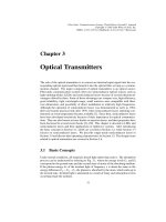
Figure 2.1.
Block Diagram of an optical intensity, direct detection communications channel.
less optical links is also briefly surveyed. Various noise sources present in
the wireless optical link are also discussed to determine which are dominant.
The chapter concludes with a comparison of popular channel topologies and a
summary of the typical parameters of a practical short-range wireless optical
channel.
2.1
Wireless Optical Intensity Channels
Wireless optical channels differ in several key ways from conventional communications channels treated extensively in literature. This section describes
the physical basis for the various amplitude and power constraints as well as
propagation characteristics in indoor environments.
2.1.1
Basic Channel Structure
Most present-day optical channels are termed intensity modulated, directdetection channels. Figure 2.1 presents a schematic of a simplified free-space
intensity modulated, direct-detection optical link.
The optical intensity of a source is defined as the optical power emitted
per solid angle in units of Watts per steradian [10]. Wireless optical links
transmit information by modulating the instantaneous optical intensity,
in
response to an input electrical current signal
The information sent on this
channel is not contained in the amplitude, phase or frequency of the transmitted
optical waveform, but rather in the intensity of the transmitted signal. Present
day optoelectronics cannot operate directly on the frequency or phase of the
range optical signal. This electro-optical conversion process is termed
optical intensity modulation and is usually accomplished by a light-emitting
diode (LED) or laser diode (LD) operating in the 850-950 nm wavelength band
[11]. The electrical characteristics of the light emitter can be modelled as a
diode, as shown in the figure. Section 2.2.1 describes the operation of LEDs
and LDs in greater detail.
The opto-electrical conversion is typically performed by a silicon photodiode. The photodiode detector is said to perform direct-detection of the incident
optical intensity signal since it produces an output electrical photocurrent,
Wireless Optical Intensity Channels
11
nearly proportional to the received irradiance at the photodiode, in units of
Watts per unit area [10]. Electrically, the detector is a reversed biased diode,
as illustrated in Figure 2.1. Thus, the photodiode detector produces an output
electrical current which is a measure of the optical power impinging on the
device. The photodiode detector is often termed a square law device since the
device can also be modelled as squaring the amplitude of the incoming electromagnetic signal and integrating over time to find the intensity. Section 2.2.2
describes the operation of p-i-n and avalanche type photodiodes and discusses
their application to wireless optical channels.
The underlying structure of the channel, which allows for the modulation and
detection of optical intensities only, places constraints on the class of signals
which may be transmitted. The information bearing intensity signal which is
transmitted must remain non-negative for all time since the transmitted power
can physically never be negative, i.e.,
Thus, the physics of the link imposes the fundamental constraint on signalling
design that the transmitted signals remain non-negative for all time. In Chapters
4–6 this non-negativity constraint is taken into account explicitly in developing
a framework for the design and analysis of modulation for optical intensity
channels.
2.1.2
Eye and Skin Safety
Safety considerations must be taken into account when designing a wireless
optical link. Since the energy is propagated in a free-space channel, the impact
of this radiation on human safety must be considered.
There are a number of international standards bodies which provide guidelines on LED and laser emissions namely: the International Electrotechnical Commission (IEC) (IEC60825-1), American National Standards Institute
(ANSI) (ANSI Z136.1), European Committee for Electrotechnical Standardization (CENELEC) among others. In this section, we will consider the IEC
standard [12] which has been widely adopted. This standard classifies the main
exposure limits of optical sources. Table 2.1 includes a list of the primary
classes under which an optical radiator can fall. Class 1 operation is most desirable for a wireless optical system since emissions from products are safe under
all circumstances. Under these conditions, no warning labels need to be applied
and the device can be used without special safety precautions. This is important
since these optical links are destined to be inexpensive, portable and convenient
for the user. An extension to Class 1, termed Class 1M, refers to sources which
are safe under normal operation but which may be hazardous if viewed with
optical instruments [13]. Longer distance free-space links often operate in class
3B mode, and are used for high data rate transmission over moderate distances
12
Wireless Optical Intensity Channels
(40 m in [14]). The safety of these systems is maintained by locating optical
beams on rooftops or on towers to prevent inadvertent interruption [15]. On
some longer range links, even though the laser emitter is Class 3B, the system
can still be considered Class 1M if appropriate optics are employed to spread
the beam over a wide enough angle.
The critical parameter which determines whether a source falls into a given
class depends on the application. The allowable exposure limit (AEL) depends
on the wavelength of the optical source, the geometry of the emitter and the
intensity of the source. In general, constraints are placed on both the peak and
average optical power emitted by a source. For most practical high frequency
modulated sources, the average transmitted power of modulation scheme is
more restrictive than the peak power limitation and sets the AEL for a given
geometry and wavelength [12]. At modulation frequencies greater than about
24 kHz, the AEL can be calculated based on average output power of the source
[11].
The choice of which optical wavelength to use for the wireless optical link
also impacts the AEL. Table 2.2 presents the limits for the average transmitted
optical power for the IEC classes listed in Table 2.1 at four different wavelengths.
The allowable average optical power is calculated assuming that the source is
a point emitter, in which the radiation is emitted from a small aperture and
diverges slowly as is the case in laser diodes. Wavelengths in the 650 nm
range are visible red light emitters. There is a natural aversion response to
high intensity sources in the visible band which is not present in the longer
wavelength infrared band. The visible band has been used rarely in wireless
optical communication applications due to the high background ambient light
noise present in the channel. However, there has been some development of
visible band wireless optical communications for low-rate signalling [16, 17].
Infrared wavelengths are typically used in optical networks. The wavelengths