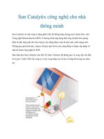
giải pháp nhà thông minh
Bạn đang xem bản rút gọn của tài liệu. Xem và tải ngay bản đầy đủ của tài liệu tại đây (2.05 MB, 16 trang )
Intelligent
Solutions
This chapter shows two simplified
examples of the use of Siemens
instabus in the residential and
the commercial buildings. These
examples serve as the method of
documentation for your projects and,
therefore, the features are kept to a
minimum.
The following states the full documentation required for any
one project:
1) Layout Drawings:
Layout Drawings show the location where products are
mounted in the building, to show the contractors where to
install the products (e.g. AP-, UP- and GE-type). If instabus
products are mounted outside the distribution board, their
mounting locations have to be indicated in this plan. Siemens
provides you with icons for flush mounted devices, surface
mounted devices and devices that are incorporated in the
equipment itself, that you can easily place them in your plan.
The layout plan also shows the basic routing of the wiring for
the connection of the instabus devices as well as for the
IR-Receivers. Different lines (dashed, dotted) indicate a different
cable type.
The routing of the 230V supply cabling is done by means of
reference numbers. For example, the index number for the
lighting group 1.1.1 (5) means: This lighting group is connected
to the instabus product with the number 1.1.1. You can find
the details of this product in the Single Line Drawing of
that project. The number in brackets (5) indicates the terminal
number of the product, so the contractor will have a reference
of where to terminate the cable of this lighting group in the DB.
For AP-, UP- and GE-type products, separate icons are used
to create Detail Drawings for termination references.
Intelligent Solutions:
Necessary Documentation ......................4-47
A Residential Project ................................4-49
A Commercial Project ...............................4-55
4-47
2) Single Line Drawings:
The Single Line Drawings are used to plan the general concept of circuit protection and power distribution of
the electrical system in a building. The Siemens instabus products for distribution box mounting are designed
to be mounted together with the circuit protection products in the same enclosure. Therefore it is recommended
to complete the single line drawings with the instabus EIB control devices mounted in the distribution boards.
Each page represents one rail in the distribution board.
The icons of the Siemens instabus products show the product name and all terminal connections to make
planning easy and efficient.
The connections between circuit protection devices, DIN-rail mounted instabus devices and then to the load
build a useful documentation of the design of the instabus installation. The symbols and the physical instabus
products can be labeled with an individual identification number (physical address) for cross reference to the
Layout Drawings, for example: 1.1.1.
The icon of this product also indicates the function of a dimmer N 527.
Detailed technical information about the products can be found in the Technical Manual “Building Management
with instabus EIB.”
3) Detail Drawings:
The Detail Drawings show the terminal connections of the AP and GE type devices. Detail Drawings are
necessary to indicate the termination of the wires to the contractor on site. When AP and GE type devices
are used in a project and documented in the layout plan, one drawing per product type is sufficient.
Detailed technical information about the products can be found in the Technical Manual “Building Management
with instabus EIB.”
The icons used in these examples can be imported in the AutoCAD software and are ready to use.
Kindly contact your Siemens partner to get the latest Siemens instabus AutoCAD library for your office.
4-48
Residential Project
The residential area, in this example, is a one-storey house with three bedrooms, living/dining area and three
bathrooms. The features included in this example are simple: on/off switching with dimming and control via
IR transmitter. The home objects controlled by instabus EIB are the lights and two heaters.
There are two IR Receivers mounted in the ceiling: one in Bedroom 1 and the other in the Living Hall.
They are connected to the IR decoder found in the Distribution Board and the line is represented by the dotted
line. IR Receivers do not require physical addresses.
There are a total of 14 light circuits, 2 heaters and 4 set of shutters. There are 4 incandescent dimming circuits
and 2 florescent dimming circuits.
The following devices were specified:
N 527 Universal Dimmer
N 528 Universal Dimmer
N 525 Switching/Dimming Actuator
N 521 Shutter Actuator
N 561 4 channel Binary Output
N 510 4 channel Binary Output
N 562 2 channel Binary Output
N 450 IR Decoder
S 440 IR Receiver
N 122 Power Supply with Choke
REG 190/01 Connector
Data Rail 16 MW
Number of Devices
2
2
2
2
1
1
2
1
2
1
4
4
Please refer to the Distribution Board drawings and the layout for correlation between light circuits and
Siemens instabus products.
4-49
Layout Drawing
4-50
Single Line Drawing
4-51
Single Line Drawing (Cont’d)
4-52
Single Line Drawing (Cont’d)
4-53
Single Line Drawing (Cont’d)
4-54
Commercial Project
In this example, the areas which are looked into are: one meeting room, the lobby/corridor area and the offices.
Lobby/Corridor Area:
For the lobby and corridor area, the lights are trigged on by Motion Detectors and will remain on for 40 minutes.
If further movement is detected within the 40 minutes, the timer will be re-set back to 0 and the lights will
remain on for a further 40 minutes.
Offices:
All lights are controlled by a Push Button located at the entrance. Only on/off switching is offered in this project.
The DIN rail mounted products for the office, lobby and corridor are found in Distribution Board 1.
The following devices are specified:
In DB 1
N 527 Universal Dimmer
N 561 4 channel Binary Output
N 302 Time Module
N 122 Power Supply with Choke
REG 190/01 Connector
Data Rail 16 MW
Number of Devices
1
1
1
1
2
2
Surface Mounted
AP 600/01 2 channel Binary Output
UP 250 Motion Detector
UP 245 4 gang DELTA profil Push Button
3
3
1
Meeting Room:
It is common that discussions and presentations are held in a meeting/conference room and to facilitate the
change of one type of usage to another, Scene Control and Infra-Red Control have been added. There are a
total of 4 lighting groups: 3 groups of dimmable halogen lamps and 1 group of dimmable florescent lamps.
A Handheld Transmitter is an added convenience to the users.
The following devices are specified:
In DB 2
N 527 Universal Dimmers
N 450 IR Decoder
N 300 Scene Module
REG 190/01 Connector
Number of Devices
3
1
1
1
Ceiling/Surface Mounted
GE 525 Switching/Dimming Actuator (located in the light fitting itself)
S 440 IR Receiver
UP 212 4 gang DELTA studio push button
AP 421 2 gang Handheld Transmitter
1
1
1
1
Points to note:
• Only 1 Power Supply is needed to supply power to the products as there are fewer than 64 programmable
products in this project.
• The physical addresses for the devices must never be repeated for the same project.
Please refer to the drawings for the detailed connection between devices and load.
4-55
Layout Drawing
4-56
Single Line Drawing
4-57
Single Line Drawing (Cont’d)
4-58
Single Line Drawing (Cont’d)
4-59
Detail Drawing
DIMMER SWITCH (GE-TYPE)
SWITCHING DEVICE (AP-TYPE)
4-60
4-61
4-62