Magnetic properties of co ta thin films and their applications in magnetic tunnel junctions
Bạn đang xem bản rút gọn của tài liệu. Xem và tải ngay bản đầy đủ của tài liệu tại đây (2.68 MB, 149 trang )
MAGNETIC PROPERTIES OF CO-TA THIN FILMS AND
THEIR APPLICATIONS IN MAGNETIC TUNNEL
JUNCTIONS
FONG KIEN HOONG
NATIONAL UNIVERSITY OF SINGAPORE
2003
MAGNETIC PROPERTIES OF CO-TA THIN FILMS AND
THEIR APPLICATIONS IN MAGNETIC TUNNEL
JUNCTIONS
FONG KIEN HOONG
(B. Eng. (Hons), NUS)
A THESIS SUBMITTED
FOR THE DEGREE OF MASTER OF ENGINEERING
DEPARTMENT OF ELECTRICAL AND COMPUTER
ENGINEERING
NATIONAL UNIVERSITY OF SINGAPORE
2003
Acknowledgment
ACKNOWLEDGMENT
The author would like to express his heartfelt gratitude to his mentors, Dr Vivian
Ng and Dr Adeyeye Adekunle for their guidance, encouragement and advice throughout
the course of the project.
The author would like to thank Miss Loh Fong Leong, Miss Liu Ling, Mr Walter
Lim, Mr Lim Boon Chow, Miss Chan Soon Yeng, Miss Pang Siew It, Miss Zhao Yan and
Mdm Ah Lian Kiat for their assistance and advice.
Special thanks to the author’s collaborators, Mr Hu Jiangfeng and Mr Chen Fang
Hao for their invaluable contributions, assistance and advice.
In addition, the author would like to express his gratitude to his colleagues, Kyaw
Min Tun, Darren, Alvin Wee, Zhao Qiang, May Thu Win, Wang Xiao Qiang, Chen Chao,
Guo Jie and Chan Hui Ling for their companionship.
Last but not least, the author would like to thank all those who have contributed to
this project in one way or another.
i
Table of contents
TABLE OF CONTENTS
ACKNOWLEDGEMENT
i
TABLE OF CONTENTS
ii
SUMMARY
vi
SYMBOLS AND ABBREVIATIONS
viii
LIST OF FIGURES
xi
LIST OF TABLES
xiv
CHAPTER 1: INTRODUCTION
1
1.1
Background
1
1.2
Objectives
4
1.3
Organization
5
CHAPTER 2: THEORY AND REVIEW
7
2.1
Introduction
7
2.2
Anisotropic Magnetoresistive Effects
8
2.3
Giant Magnetoresistive Effects
10
2.4
Tunneling Magnetoresistive Effects
14
2.5
Related Works on Materials Used in MTJ
19
2.6
Related Works on MTJ
21
2.7
Motivation
24
2.8
Summary
25
ii
Table of contents
CHAPTER 3: EXPERIMENTAL METHODOLOGIES
28
3.1
Introduction
28
3.2
Fabrication Techniques and Equipment
30
3.2.1: Types of Substrates
30
3.2.2: Cleaning
31
3.2.3: Lithography
31
3.2.4: Deposition
33
3.2.5: Lift-off
38
Characterization Techniques and Equipment
39
3.3.1: Thickness Characterization
39
3.3.2: Magnetic Properties Characterization
39
3.3.3: Imaging of Samples
42
3.3.4: Measurement Setups
47
Summary
50
3.3
3.4
CHAPTER 4: CHARACTERIZATION OF THIN FILMS
51
4.1
Introduction
51
4.2
Seed Layer
53
4.2.1: Characterization of Ni80Fe20
53
4.2.2: Characterization of Ta
55
4.3
Bottom Electrode
58
4.4
Insulating Barrier
59
4.5
Top Electrode
63
4.5.1: Co as Top Electrode
63
iii
Table of contents
4.6
4.7
Co-Ta Alloy
65
4.6.1: Calibration of Co and Ta
65
4.6.2: Coercivity of Co-Ta Films
66
4.6.3: TEM of Co-Ta Grains
68
4.6.4: MFM Images of Co-Ta Films
69
4.6.5: TEM Images of Co-Ta Films
71
4.6.6: Crystal Structure of Co-Ta Films
72
4.6.7: Surface Roughness of Co-Ta (15%)
75
4.6.8: Summary of Studies on Co-Ta Films
76
Summary
77
CHAPTER 5: MAGNETIC TUNNEL JUNCTIONS
78
5.1
Introduction
78
5.2
Shadow Mask Design I
81
5.3
Magnetic Tunnel Junctions Using Shadow Mask I
85
5.3.1: Deposition Conditions
85
5.3.2: VSM Measurement
86
5.3.3: I-V Measurements
87
5.3.4: MR Measurements
87
5.4
Shadow Mask Design II
96
5.5
Shadow Mask II Magnetic Tunnel Junctions with Co Electrode
99
5.5.1: Deposition Conditions
99
5.5.2: VSM Measurement
100
5.5.3: I-V Measurements
100
iv
Table of contents
5.6
5.7
5.5.4: MR Measurements
101
5.5.5: Comparison of Batch N with Batch G
104
Magnetic Tunnel Junctions with Co-Ta Electrode
105
5.6.1: Deposition Conditions
105
5.6.2: VSM Measurement
106
5.6.3: I-V Measurements
106
5.6.4: MR Measurements
107
5.6.5: Comparison of Batch N with Batch G
109
5.6.6: Review of Magnetic Tunnel Junctions Fabricated
111
Summary
113
CHAPTER 6: CONCLUSION AND FUTURE
RECOMMENDATIONS
115
6.1
Conclusion
115
6.2
Problems Encountered
117
6.3
Future Recommendations
119
Appendix
A.
Shadow Mask Design I
121
B.
Shadow Mask Design II
125
C.
MR Measurements of Batch G at 0°
129
D.
MR Measurements of Batch G at 90°
131
List of Publications
133
v
Summary
SUMMARY
Magnetic tunnel junctions (MTJ) show great promise to become the next
candidate for magnetic data storage devices like the hard disk and magnetic random
access memory. This is due to their sensitivity to low magnetic fields, non-volatility as
well as radiation hardness. The common structure of a MTJ consists of two ferromagnetic
layers sandwiching a thin insulating layer. The common ferromagnetic materials used
include Ni80Fe20 and Co.
In this project, the metal Ta was examined to determine its suitability as the base
contact of the MTJ. It was found that Ni80Fe20 gives a smoother film than Ta, thus
discounting the use of Ta as the base contact. The alloy Co-Ta was also examined to
determine its suitability to be part of the tri-layer structure. It was found that the Co-Ta
film exhibits vastly different magnetic properties when doped with different
concentrations of Ta. The coercivity of Co-Ta films initially increases with the increase in
Ta ratio, but once the concentration reaches 15%, the coercivity decreases rapidly until
around 10 Oe. It was found that the changes in magnetic properties of the Co-Ta films are
due to many contributing factors. The factors are namely grain size changes, presence of
different crystal orientations, different degrees of crystallinity as well as different
magnetic domain configurations. The variation in coercivity of the Co-Ta material
suggests a possibility of using it to replace Co as the top electrode to complement the
bottom electrode Ni80Fe20.
vi
Summary
MTJ devices of Ni80Fe20/Al2O3/Co tri-layer were fabricated using shadow masks.
The devices show a large dependence on the shape of the electrodes. It was found that the
orientation of the top electrode is critical in giving a better magnetoresistive response.
Subsequently, another batch of devices was fabricated using a different set of shadow
masks in order to reduce the shape anisotropic effects. This has succeeded to a certain
extent in that the switching fields of the electrodes are much lower compared to the
previous batch. A third batch of devices using Co-Ta as the top electrode was fabricated.
It was found that MTJs using this material still exhibit tunneling characteristics, but
however, the magnetoresistive ratio was lower than when only Co was used. This was
attributed to the presence of the non-magnetic Ta, which reduced the spin polarization of
Co.
vii
Symbols and Abbreviations
SYMBOLS AND ABBREVIATIONS
Å
Angstroms (10-10 m)
Al
Aluminium
Al2O3
Aluminium oxide
AFM
Atomic Force Microscope
AMR
Anisotropic Magentoresistive
Ar
Argon
B
Magnetic flux density
Co
Cobalt
Co50Fe50
Cobalt Iron alloy with 50% Cobalt and 50% Iron composition
Cr
Chromium
D(EF)
Density of electron states near the Fermi level
DI
De-ionized
DC
Direct Current
EF
Fermi energy
Fe
Iron
FM
Ferromagentic
GMR
Giant Magnetoresistive
H
Magnetic field strength
HC
Coercivity
I
Current
IPA
Iso-propanol
k
Fermi wave vactors
viii
Symbols and Abbreviations
O
Oxygen
M
Magnetization
MFM
Magnetic Force Microscope
Mo
Molybdenum
MRAM
Magnetic Random Access Memory
MTJ
Magnetic Tunnel Junction
n
Nano (10-9 m)
Ni80Fe20
Nickel Iron permalloy with 80% Nickel and 20% Iron compostion
Oe
Oersteds
P
Spin polarization
R
Resistance
RF
Radio frequency
sccm
Standard cubic centimeter
Si
Silicon
SiO2
Silicon dioxide
SMU
Source Measuring Unit
SPM
Scanning Probe Microscope
Ta
Tantalum
TMR
Tunneling Magnetoresisitve
V
Voltage
VSM
Vibrating Sample Magnetometer
XRD
X-ray diffraction
Ψ
Wave function
κ
Decaying wave vector
ix
Symbols and Abbreviations
µ
Micro (10-6 m)
Ω
Ohms
∆
Change in
θ
Angle
º
Degree
x
List of Figures
LIST OF FIGURES
Fig 2.2.1
Schematic showing AMR effects under a) no external field and
b) external field H.
8
Fig 2.2.2
Variation of magnetoresistance with angle θ of magnetization
field and current.
9
Fig 2.3.1
Schematic diagram showing scattering conditions at
a) No external magnetic field and b) External magnetic
field and into saturation.
11
Fig 2.3.2
Magnetoresistance of three Fe/Cr superlattices at 4.2 K. The
Current and applied field are along the [110] axis
in the plane of the layer.
12
Fig 2.4.1
Energy band diagrams of FM/I/FM systems. D(ε) denotes the
density of states and dashed line represent the Fermi levels.
The spin-up band is split from the spin-down band due
to exchange interaction. It is assumed there is no spin flipping.
14
Fig 2.4.2
Schematic of MRAM device.
17
Fig 3.2.1
Flow chart of fabrication process.
30
Fig 3.2.2
Flow chart of fabrication process.
32
Fig 3.2.3
Schematic of KVT EV 2000 Thermal/E-Beam Evaporator.
34
Fig 3.2.4
Schematic of Cryovac Sputtering Machine.
36
Fig 3.2.5
Dislodgement of target by a heavier atom.
37
Fig 3.3.1
Schematic of VSM.
40
Fig 3.3.2
Schematic of SPM.
45
Fig 3.3.3
Schematic of the measurement setup.
48
Fig 4.1.1
Schematic top view of MTJ device.
51
xi
List of Figures
Fig 4.1.2
Schematic side view of MTJ device.
51
Fig 4.2.1
Ni80Fe20 thickness versus time.
54
Fig 4.2.2
AFM images of Ta deposited at various conditions with
(i) No RF bias, (ii) 10 W RF bias, (iii) 20 W RF bias,
(iv) 30 W RF bias and (v) Evaporation.
56
Fig 4.4.1
Hysteresis loop of tri-layer with sputtered Al2O3 barrier.
60
Fig 4.4.2
Hysteresis loop of tri-layer with plasm oxidized Al barrier.
61
Fig 4.5.1
Coercivity versus thickness curve of Co.
63
Fig 4.6.1
Sputtering rate of Ta at various RF powers.
66
Fig 4.6.2
Coercivity versus Ta by sputter ratio of Co-Ta alloy.
67
Fig 4.6.3
TEM images showing the grain sizes of (i) Co-Ta of 10% Ta
ratio, (ii) Co-Ta of 15% Ta ratio, (iii) Co-Ta of 20% Ta ratio
and (iv) Co-Ta of 25% Ta ratio.
68
Fig 4.6.4
MFM images of (i) Co, (ii) Co-Ta (5%), (iii) Co-Ta (10%),
(iv) Co-Ta (15%), (v) Co-Ta (20%) and (vi) Co-Ta (25%)
69
.Fig 4.6.5
TEM images showing the crystal structures of (i) Co-Ta
of 10% Ta ratio, (ii) Co-Ta of 15% Ta ratio, (iii) Co-Ta of
20% Ta ratio and (iv) Co-Ta of 25% Ta ratio.
71
Fig 4.6.6
XRD result of Co-Ta samples.
73
Fig 4.6.7
Surface roughness analysis of Co-Ta (15%), roughness=0.758 nm 75
Fig 5.1.1
Hysteresis loop of an ideal FM/I/FM structure. The orange path
78
shows the forward sweep of the magnetic field while the blue path
shows the backward sweep.
Fig 5.1.2
MR measurement of an ideal MTJ with the tri-layer used in
figure 5.1.1. The orange path shows the forward sweep of the
magnetic field while the blue path shows the backward sweep.
79
Fig 5.2.1
Design patterns of Shadow Mask I, (i) Bottom electrode,
(ii) Barrier, (iii) Top electrode and (iv) Contact pads.
81
xii
List of Figures
Fig 5.2.2
Merged pattern of Figure 5.2.1. Arrow points to one of the devices 82
in the mask.
Fig 5.3.1
Hysteresis loop of reference sample A.
86
Fig 5.3.2
I-V curve of a representative sample from batch G
87
Fig 5.3.3
MR curves of i) GB2_0, ii) GC3_0, iii) GB2_90 and iv) GC3_90. 88
Fig 5.3.4
MR ratio versus junction area.
Fig 5.3.5
MR curves of devices i) GB4_0 and ii) GD2_0, iii) GB4_90 and 93
iv) GD2_90. The applied magnetic field is perpendicular to the top
electrode for (i) and (ii) and parallel to the top electrode for (iii)
and (iv). All devices have the same junction areas.
Fig 5.4.1
Design Pattern of Shadow Mask II, (i)Bottom electrode, (ii)Barrier, 96
(iii)Top electrode and (iv)Contact pads.
Fig 5.4.2
Merged pattern of Figure 5.4.1. Blue rectangles show the actual
device.
97
Fig 5.5.1
Hysteresis loop of reference sample B.
100
Fig 5.5.2
I-V curve of a representative sample from batch N.
100
Fig 5.5.3
MR curves of (i) NA1_0, (ii) NB1_0, (iii) NA2_0 and (iv) NB2_0. 101
Fig 5.5.4
MR curves of (i) NA1_90, (ii) NB1_90, (iii) NA2_90 and
(iv) NB2_90.
102
Fig 5.6.1
Hysteresis loop of reference sample C.
106
Fig 5.6.2
I-V curve of a representative sample from batch P.
106
Fig 5.6.3
MR curves of (i) PA1_0, (ii) PB1_0, (iii) PA2_0 and (iv) PB2_0. 107
Fig 5.6.4
MR curves of (i) PA1_90, (ii) PB1_90, (iii) PA2_90 and
(iv) PB2_90.
xiii
92
108
List of Tables
LIST OF TABLES
Table 3.3.1
Comparisons between the various modes of AFM.
44
Table 4.2.1
Surface roughness of Ni80Fe20 films deposited at various
conditions.
55
Table 4.2.2
Surface roughness of Ta films deposited at various conditions.
57
Table 5.2.1
Dimensions of devices.
83
Table 5.2.2
Areas and aspect ratios for the various devices.
83
Table 5.3.1
Deposition conditions used.
85
Table 5.3.2
MR ratios of batch G measured at i) 0° and ii) 90°. The dash
denotes the absence of measurement data
91
Table 5.4.1
Areas and aspect ratios of various designs
98
Table 5.5.1
Deposition conditions used
99
Table 5.5.2
MR ratios of batch N measured at (i) 0° and ii) 90.
103
Table 5.6.1
Deposition conditions used.
105
Table 5.6.2
MR ratios of batch P measured at (i) 0° and ii) 90.
109
xiv
Chapter 1
Introduction
CHAPTER 1
INTRODUCTION
1.1
BACKGROUND
The invention of paper by the Chinese represented a great step forward for the
human race in their pursuit of knowledge. It allows us to record our observations and
findings, and provided us an avenue to communicate with one another more easily.
However, with the explosion of knowledge brought about by the present technological
age, it is no longer efficient to store information on paper alone. Data storage devices thus
are important to help us store and retrieve data more easily and economically. This helps
to facilitate mankind’s quest for knowledge.
There are many different data storage devices available, from magnetic tapes,
compact disks and magnetic hard disks. Each has their own advantages and
disadvantages, but the hard disk remains the most popular data storage device, because of
its storage capacity and speed of access. With research going into storage density of
tetrabit/in2, hard disk will remain as our main data storage device for the foreseeable
future.
Conventional hard disk head uses an inductive element to detect magnetic changes
in the hard disk media. However, this inductive element needs to be magnetized by
existing flux in the media, and hence places a limit as to the size of the magnetic domains
that can be read. By contrast, a magnetoresistive (MR) head senses the existing flux in the
1
Chapter 1
Introduction
hard disk, and is therefore much more sensitive, and allows for a larger capacity hard
disk.
One of the more promising MR sensors is the magnetic tunnel junction (MTJ),
which comprises of two ferromagnetic layers sandwiching a thin insulator (FM/I/FM).
Besides being small, MTJ is sensitive, non-volatile and resistant to radiation. These
qualities enable it to be employed as magnetic random access memory (MRAM), read
head sensors, large arrays of sensors for imaging and ultra-low-field sensors.
Julliere[1] first reported MR effects at 4.2 K of about 14% MR ratio for a Fe/Ge/Fe
and Fe/Ge/Co junction in 1975. Since then, the interests in MTJs subsided due to the
technical difficulties in making high quality barriers. It was not until some 20 years later
that this obstacle was cleared due to advancement in deposition techniques. As of now, a
MR ratio of 58.8% was reported[2] by a group of Japanese researchers using a
Ta/Cu/Ta/NiFe/Cu/MnIr/CoFe/AlO/CoFe/NiFe/Cu/Ta structure with the barrier being
plasma oxidized using a mixed inert gas of Kr-O2. This represents a four-fold increase in
MR ratio from Julliere’s experiments, and the number of layers used has also increased
by nearly 4 times.
Although the improvements in deposition techniques have played an important
part in developing MTJ devices of higher sensitivity, design structure improvements have
also played a major role. The introduction of anti-ferromagnetic materials into the MTJ
structure is a good example. The improvement in surface roughness of the films is also
critical. In this area, the use of tantalum has helped to reduce surface roughness as well as
2
Chapter 1
Introduction
inducing the required crystal structure for the anti-ferromagnetic film. In addition, the
choice of ferromagnetic layers that are used in the MTJ structure determines the
sensitivity of the device.
3
Chapter 1
1.2
Introduction
OBJECTIVES
The objectives of this project centers around the use of tantalum in the fabrication
of MTJ devices:
1)
Design shadow and photo masks for the fabrication of MTJ devices.
2)
Explore the use of tantalum as part of the base contact of the device
3)
Explore the possibility of using a new ferromagnetic layer for the fabrication of
MTJ devices.
4
Chapter 1
1.3
Introduction
ORGANISATION OF THESIS
The thesis is divided into six main chapters, as detailed in the Table of Contents
Chapter 2 discusses the theory on magnetoresistance, including anisotropic, giant
and tunneling magnetoresistance. In addition, there will be a review on some of the works
done on MTJ by other researchers. This section includes work that are investigated on the
materials used in the MTJ as well as work done on the device proper. The motivation for
the project is also included here.
Chapter 3 will focus on the various experimental techniques and equipment used
in this project. The theory on some of the more heavily used equipment will be presented.
Chapter 4 discusses on the materials used in the MTJ. These include Ni80Fe20, Co,
Al2O3 as well as Co-Ta alloy. The main focus will be on Co-Ta, in which in-depth studies
on its magnetic properties were made.
Chapter 5 examines the devices made using shadow mask patterns. It will include
the measurement results of a Co/Al2O3/Ni80Fe20 structure as well as a CoTa/Al2O3/Ni80Fe20 structure.
The last chapter, Chapter 6, concludes this thesis by examining the problems faced
during the course of this project, as well as providing future directions for this area of
research.
5
Chapter 1
Introduction
References:
[1] M. Julliere, Phys. Lett., 54A, 225, (1975).
[2] M. Tsunoda, K. Nishikawa, S. Ogata and M. Takahashi, Appl. Phys. Lett., 80, 3135,
(2002).
6
Chapter 2
Theory and Review
CHAPTER 2
THEORY AND REVIEW
2.1
Introduction
The resistivity of a metal is dependent on its inherent impurities and defects which
cause electron scattering. The change of this resistance in the presence of an applied
external magnetic field is termed as magnetoresistance (MR). For most metals, this effect
is very small, usually within the order of 5%[1]. The origin of this effect stems from the
fact that the trajectory of an electron changes in the presence of a magnetic field, as
described by electromagnetic theory[2]. As such, this effect is more pronounced in
ferromagnetic materials, and all MR devices use ferromagnetic materials in some form.
Depending on the ways ferromagnetic materials are employed, different MR
effects will occur. In this chapter, we will discuss the more important phenomena
associated with MR effect: anisotropic magnetoresistive (AMR), giant magnetoresistive
(GMR) and tunneling magnetoresistive (TMR) effects. These will be illustrated in detail
in the following sections.
After the discussion on the various theories, we will review some of the work
done by other researchers.
7
Chapter 2
2.2
Theory and Review
Anisotropic Magnetoresistive (AMR) Effects
Anisotropic magnetoresistance (AMR) can be observed in any known
ferromagnetic material. The AMR effect is the variation of the resistivity with the
orientation between an external magnetic field and the current applied through the
ferromagnetic film[3].
One of the more commonly used materials where AMR effects are observed is the
permalloy (NiFe). As such, we illustrate the AMR effects with a permalloy film.
Current I
Easy Axis
ө
Magnetization M
a) No external field applied
Current I
ө
Magnetization M
Easy Axis
External H field
b) External field applied
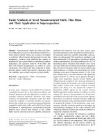
Figure 2.2.1: Schematic showing AMR effects under a) no external field and b) external field H
From figure 2.2.1 above, we can see that the magnetization M of the permalloy
film is influenced by the application of a magnetic field H. In general, the resistivity of
the permalloy film will vary as the angle between the applied magnetization and the
current is varied, and this is depicted in figure 2.2.2.
8
Chapter 2
Theory and Review
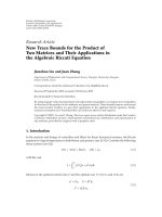
Figure 2.2.2: Variation of magnetoresistance with angle Ө of magnetization field and current
The AMR effect finds applications in the hard disk industry, where the permalloy
material is used in the MR read head of the hard disk. However, due to the small
sensitivity of AMR effects, many modifications are needed in order for the material to be
successfully implemented in the hard disk[4].
9