Modeling the effect of liquid viscosity and surface tension on bubble formation
Bạn đang xem bản rút gọn của tài liệu. Xem và tải ngay bản đầy đủ của tài liệu tại đây (507.02 KB, 97 trang )
MODELING THE EFFECT OF LIQUID
VISCOSITY AND SURFACE TENSION ON BUBBLE
FORMATION
ZHANG YALI
NATIONAL UNIVERSITY OF SINGAPORE
2004
MODELING THE EFFECT OF LIQUID
VISCOSITY AND SURFACE TENSION ON BUBBLE
FORMATION
ZHANG YALI
(B. ENG, HUT)
A THESIS SUBMITTED
FOR THE DEGREE OF MASTER OF ENGINEERING
DEPARTMENT OF CHEMICAL AND BIOMOLECULAR ENGINEERING
NATIONAL UNIVERSITY OF SINGAPORE
2004
ACKNOWLEDGEMENT
I would like to express my deep appreciation to my supervisor, Associate Professor
Reginald B. H. Tan, for his invaluable advice, patient and continuous encouragement
throughout the project.
Particular thanks to Dr. Deng Rensheng for his assistance in the programming, Mr. Xiao
Zongyuan, Miss Xie Shuyi for their supportive discussion on this work.
I extremely appreciate my family for their deep love and support for me during the whole
study process.
Finally I would like to give my thanks to National University of Singapore for supporting
me to complete my work.
i
TABLE OF CONTENTS
Acknowledgement
i
Table of contents
ii
Summary
vi
Nomenclature
viii
List of figures
xiii
List of tables
Chapter 1
xv
Introduction
1
1.1 Significance and objective for study of single bubble formation
1
1.2 Factors affecting the bubble formation at a submerged orifice
1
1.3 Organization of thesis
3
Chapter 2
Literature Review
5
2.1 Introduction
5
2.2 Overview of the literature models and forces introduced
5
2.3 Spherical model
7
2.3.1 The model of Davidson and Schüler
7
2.3.2 The models of Hayes et al. and Sullivan et al.
8
2.3.3 The model of Swope
10
ii
2.3.4 The model of Ramakrishnan et al.
11
2.3.5 The model of Tsuge and Hibino
13
2.3.6 The model of Miyahara et al.
15
2.3.7 The model of Gaddis and Vogelpohl
16
2.3.8 The model of Deshpande et al.
18
2.4 Pseudo-spherical models
19
2.4.1 The model of Pinczewski
19
2.4.2 The model of Terasaka and Tsuge
21
2.4.3 The model of Yoo et al.
24
2.5 Non-spherical models
24
2.5.1 The model of Marmur and Rubin
25
2.5.2 The model of Hooper
26
2.5.3 The model of Tan and Harris
27
2.5.4 The model of Liow and Gray
29
2.6 Summary
Chapter 3
31
Theoretical Model Development
32
3.1 Introduction
32
3.2 Bubbling system and assumptions
32
3.3 Equations of motion
34
3.3.1 Force analysis based on the interfacial elements
34
3.3.2 Calculation of the virtual mass
38
3.4 Thermodynamics of the bubbling system
40
iii
3.5 Summary
Chapter 4
42
Numerical Solution
43
4.1 Introduction
43
4.2 Initial conditions
43
4.3 Boundary conditions
45
4.4 Finite time-difference procedure
45
4.4.1 Finite difference versions of equations of motion
45
4.4.2 Finite difference versions of thermodynamic equations
47
4.5 Calculation of interfacial coordinates
50
4.6 Simulation of bubble growth process
51
Chapter 5
Results and Discussion
54
5.1 Bubble growth curve and bubble shape during formation
54
5.2 Effect of viscosity on the bubble volume
59
5.3 Effect of surface tension
62
5.4 Comparison of experimental and simulated values of bubble volume
64
5.5 Analysis on modified Reynolds number
66
5.5.1 Expression for modified Reynolds number
66
5.5.2 Values comparison of modified Reynolds number
67
5.5.3 Conclusion
71
iv
Chapter 6
Conclusions and Recommendations
72
6.1 Conclusions
72
6.2 Recommendations for future work
72
References
74
v
SUMMARY
Many physical and chemical engineering processes involve heat or mass transfer across
an interface at which two immiscible fluids contact. In such operations a large interfacial
area per unit volume is necessary to bring about efficient mass and heat transfer between
the two phases. The method of gas dispersion through submerged nozzles, orifices or
slots is the simplest and the most common, which permits simple design and leads to
reasonably large interfacial areas. Due to the extremely complicated phenomena involved
in this process, a somewhat simplified starting point has been to consider bubble
formation from a single submerged orifice beneath the liquid, which has been the subject
of study by many investigators.
An improved non-spherical model for bubble formation and detachment at a submerged
orifice has been developed. The model is based on the interfacial element approach of
Tan and Harris (1986), and is modified to include the influence of viscosity in a
Newtonian liquid via a viscous drag force on each interfacial element.
The gas-liquid interface is divided into a finite number of differential elements, and
equations of motion are applied to each element to calculate the instantaneous
coordinates constituting the bubble shape during its motion. One powerful advantage of
this model is that there is no need for an empirical detachment criterion because the
vi
instant of detachment occurs naturally as a consequence of bubble growth and shape
evolution.
vii
NOMENCLATURE
Symbol
Description
Unit
a0
cross-sectional area of orifice
C
orifice flow coefficient
dimensionless
C'
effective orifice coefficient
dimensionless
c0
velocity of sound in the gas
CD
drag coefficient
dimensionless
D
orifice diameter
m
Db
diameter of bubble in Equation (2.1)
m
De
equivalent diameter of bubble ( De = 3
Dm
maximum horizontal diameter of bubble in Equation (2.15)
m
F
upward force in Equation (2.13)
N
Fb
buoyancy force
N
FD
viscous drag force
N
Fep
excess pressure force
N
Fi
inertial force
N
Fm
force due to the momentum of gas
N
m2
m/s
6Vb
π
)
m
viii
Fp
force due to pressure
N
Fσ
force caused by surface tension
N
g
gravitation acceleration
g0
constant of proportionality in Newton’s 2nd law
m/s2
in section 2.3.3
dimensionless
H
liquid height above orifice plate
m
l
length of tuyere
m
M
virtual mass
Kg
Mb
mass of gas in the bubble
Kg
M'
added mass
Kg
∆M
differential virtual mass
Kg
N
number of interface elements
dimensionless
NC
capacitance number
dimensionless
N FR
Froude number ( N FR =
N WE
Weber number ( N WE =
Pa
pressure at the supply
Pa
Pb
pressure in the bubble
Pa
Pc
pressure in the chamber
Pa
P0
hydrostatic pressure at the orifice plate
Pa
Ps
system pressure
Pa
gπ 2 D 5 (ρ l − ρ g )
24 ρ g q 2
4ρ g q 2
π 2 D 3σg 0
)
)
dimensionless
dimensionless
ix
P∞
static liquid phase pressure
q
gas flowrate through the orifice
m3/s
Qg
gas flow rate into the system
m3/s
r
radial coordinate from axis of the bubble
m
r'
bubble radius (Figure 2.1)
m
r0
radius of the orifice
m
rE
vertical distance (Figure 2.2)
m
rF
radius of bubble (Figure 2.2)
m
ri
neck radius
m
r
equivalent spherical radius of bubble in Equation (2.2)
m
R
equivalent radius of curvature at a point on the bubble surface
m
R1
principal radius described (Figure 2.3 and2.4)
m
R2
principal radius described (Figure 2.3 and2.4)
m
Re
Reynolds number ( Re =
Re '
modified Reynolds number ( Re ' =
s
arc length
m
s0
vertical distance of bubble from the plate floor in Equation (2.13)
m
t
time
u
liquid velocity
m/s
ur
velocity of each element in r - direction
m/s
Pa
De ρ l u
µ
)
dimensionless
ρcQ
)
πr0 µ
dimensionless
s
x
uz
velocity of each element in z - direction
u
velocity of the interface element in liquid ( u = u r + u z )
m/s
v
vertical average velocity over the surface of bubble
m/s
v0
velocity of gas through the orifice
Vb
bubble volume
m3
Vc
chamber volume
m3
Vh
orifice velocity in Equation (2.10)
m/s
Vy
steady bubble rising velocity in Equation (2.1)
m/s
y
vertical distance of bubble center from the orifice plate
m
z
axial coordinate from orifice plate
m
m/s
2
2
m/s
Greek letters
Symbol
Description
Unit
α
added mass coefficient
dimensionless
β
contact angle in Equation (2.27)
dimensionless
χ
coefficient in Equation (2.2)
dimensionless
ε
tolerance value
dimensionless
φ
liquid velocity
dimensionless
ϕ
angle between gas-liquid interface and horizontal plane
dimensionless
γ
adiabatic gas coefficient
dimensionless
κ
viscosity ratio ( κ = µ g µ l )
dimensionless
xi
µg
gas viscosity
Pa.s
µl
liquid viscosity
Pa.s
θ
angle defined in Equation (2.10)
ρa
gas density at supply
Kg/m3
ρb
gas density in the bubble
Kg/m3
ρc
gas density in the chamber
Kg/m3
ρl
liquid density
Kg/m3
σ
surface tension
N/m
ω
angle of revolution about bubble axis (Fig. 4.1)
dimensionless
ψ
function of inertial and viscous forces in Equation (2.3)
dimensionless
dimensionless
xii
LIST OF FIGURES
Fig. 2.1.
One-stage bubble formation model in viscous liquid by Davidson
and Schüler (1960a)
8
Two-stage bubble formation process by Ramakrishnan et al.
(1969)
12
Fig. 2.3.
Schematic of bubble formation model by Pinczewski (1981)
21
Fig. 2.4.
Pseudo-spherical bubble formation model by Terasaka and Tsuge
(1990)
23
Fig. 3.1.
Schematic diagram of bubbling system
33
Fig. 3.2.
Two-dimensional coordinate diagram of interfacial element
34
Fig. 3.3.
Three-dimensional interfacial element and forces on it
35
Fig. 4.1.
Initial volume of an interfacial element pre unit angle of revolution
45
Fig. 4.2.
Volume change of interfacial element with time
51
Fig. 4.3.
Flowchart of computation procedure
53
Fig. 5.1.
Bubble growth rate with time. Experimental data from LaNauze
and Harris (1974a). System: CO2-water, Vc = 375 cm3, r0 = 0.16
cm, µ = 0.001 Pa.s, Qg = 10 cm3/s
55
Comparison of bubble growth rate between bubble formation in
inviscid and viscous liquids. System: Vc = 375 cm3, r0 = 0.16 cm,
Q g = 10 cm3/s
56
Fig. 2.2.
Fig. 5.2.
Fig. 5.3.
Simulated bubble shapes during formation for inviscid and viscous
liquids. System (a) N2-water: Vc = 375 cm3, r0 = 0.16 cm, µ =
0.001 Pa.s, Qg = 10 cm3/s. (b) N2-92wt%glycerol: Vc = 375 cm3, r0
= 0.16 cm, µ = 0.154 Pa.s, Qg = 10 cm3/s
57
xiii
Fig. 5.4.
Fig. 5.5.
Fig. 5.6.
Fig. 5.7.
Fig. 5.8.
Fig. 5.9.
Bubble growth rate with time. Experimental data from Terasaka
and Tsuge (1990). System: N2-92wt%glycerol, µ = 0.154Pa.s, r0
= 0.0735 cm, Qg = 1.1 cm3/s, Vc = 42.5 and 97.5 cm3
58
Effect of gas flow rate on the bubble volume with different
chamber volumes. Experimental data from Terasaka and Tsuge
(1990). System: N2-90wt%glycerol, µ = 0.118Pa.s, r0 = 0.0765
cm, Vc= 34.1, 75 and 286 cm3
60
Effect of gas flow rate on the bubble volume with different liquid
viscosities. Experimental data from Ramakrishnan et al. (1969).
System: air-glycerol solution, r0 = 0.352 cm, Vc = 50 cm3
61
Effect of gas flow rate on the bubble volume with different orifice
diameters. Experimental data from Ramakrishnan et al. (1969).
System: air-glycerol solution, Vc = 50 cm3, µ = 0.045 Pa.s, r0 =
0.184, 0.298 and 0.352 cm
62
Effect of surface tension on bubble volume. Experimental data
from Ramakrishnan et al. (1969). System: air-water, σ = 71.1
mN/m; air-10% isopropanol solution, σ = 41.4 mN/m; Vc = 50
cm3, r0 = 0.298 cm; Experimental data (Davidson and Schüler,
1960b). System: air-water σ = 72.7 mN/m, air-petroleum ether,
σ = 27.1 mN/m, Vc = 50 cm3, r0 = 0.0334 cm.
64
Comparison of calculated and experimental values of bubble
volume
65
xiv
LIST OF TABLES
Table 2.1
An outline for the literature models and forces
6
Table 5.1
Values of modified Reynolds number I
68
Table 5.2
Values of modified Reynolds number II
69
Table 5.3
Values of modified Reynolds number III
69
Table 5.4
Values of modified Reynolds number IV
70
xv
Introduction
CHAPTER 1
INTRODUCTION
1.1 Significance and objective for the study of single bubble formation
Many chemical engineering operations involve transfer of mass or heat across an
interface with which two immiscible fluids contact. In such operations a large interfacial
area per unit volume is necessary to cause efficient mass and heat transfer. The approach
of gas dispersion through submerged nozzle and orifice is the simplest and the most
common, which permits of extremely simple design and leads to reasonably large
interfacial areas. Such important industrial operations involving bubble formation include
bubble columns, sieve plate columns and fermentation vessels.
In the study on bubble formation, the behavior of single bubble formation through a
single submerged orifice has been widely investigated in the literature, even though
multiple orifices are practically employed in industry. The study of bubble formation at a
single submerged orifice is a relatively simple and fundamental process to model the
rather complicated multiple orifices used in practical industry; however, even this
simplified method to dispersion studies is far from being simple and clearly understood.
1.2 Factors affecting the bubble formation at a submerged orifice
1
Introduction
Bubble formation at a submerged orifice is a process in which many parameters are
involved, affecting the bubble size, bubble shape and bubble frequency and so on.
Hughes et al. (1955) investigated the variables involved in bubble formation and
proposed a dimensionless capacitance number to correlate the effects of these factors as
follows:
NC =
Vc g (ρ l − ρ g )
πr0 2 ρ g c0 2
(1.1)
where Vc is the gas chamber volume, r0 is the radius of the orifice and c0 is the velocity
of sound in the gas. Hughes et al. postulated that N C = 0.85 is the critical value to
describe the gas chamber effect. When N C < 0.85 the bubble volume is found to be
nearly independent of chamber volume.
Kumar and Kuloor (1970) classified the factors affecting bubble formation as equipment
variables, system variables and operating variables.
(1) Equipment variables
(a) The orifice radius r0 .
(b) The wetting properties of the material of the orifice.
(c) The gas chamber volume Vc .
(2) System variables
(a) The surface tension σ .
(b) The density of liquid ρ l and viscosity µ l .
2
Introduction
(c) The density of gas ρ g and viscosity µ g .
(d) The contact angle θ .
(e) The velocity of sound in the gas c 0 .
(3) Operating variables
(a) The volumetric flowrate of the gas through the orifice q .
(b) The velocity of liquid phase u .
(c) The submergence of the orifice below the liquid H
(d) The pressure drop through the orifice ∆P .
1.3 Objective and organization of thesis
The present thesis aims to model the effect of liquid viscosity and surface tension on
bubble formation through a single submerged orifice.
Chapter 2 presents a comprehensive review of theoretical and experimental studies on
bubble formation at a single submerged orifice under various conditions, in which the
influence of liquid viscosity and surface tension will be discussed in detail.
Chapter 3 introduces the theoretical development for the present model, which is based
on the interfacial element approach for non-spherical bubble formation model. The gasliquid interface is presented by a number of points with two coordinates which can be
obtained by solving the equations of motion based on the bubble surface.
3
Introduction
Detailed numerical solutions for bubble formation process will be given in chapter 4. In
addition, this chapter describes the finite time difference forms for equations of motion as
well as the thermodynamic equations.
Results and discussion will be presented in chapter 5. The effect of liquid viscosity and
surface tension on bubble formation and volume will be discussed under various
operating conditions. The comparison between theoretical predictions and experimental
results will be addressed.
Chapter 6 concludes the model predictions and also proposes recommendations for
further work.
4
Literature Review
CHAPTER 2
LITERATURE REVIEW
2.1 Introduction
Bubble formation at a single submerged orifice has been extensively studied based on
both theoretical and experimental work, which is a preliminary groundwork to fully
understand the multi-orifices gas-liquid contacting equipments in practical industry. The
various factors affecting the bubble formation frequency, bubble final volume and bubble
shape have been pointed out and validated by many investigators, of which the liquid
viscosity and gas-liquid interfacial tension are of importance, and modeling their
influence is significant in the design of gas-liquid contacting equipment.
This chapter briefly reviews the theoretical and experimental work in the literature with
three categories: spherical, pseudo-spherical and non-spherical models.
2.2 Overview of the literature models and forces introduced
In this section the different literature models will be classified and shown in Table 2.1.
Most of the models employ the equation of motion to analyze the formation of bubble,
following the method proposed by Davidson and Schüler (1960a, b), which is developed
by correlating the forces acting on the bubble surface. The forces appeared in the models
5
Literature Review
include buoyancy force Fb , surface tension force Fσ , drag force FD , inertial force Fi ,
force due to the momentum of gas Fm , force due to the pressure differences between the
gas in the bubble and the liquid F p and so on. These forces and the corresponding
formulas will be generalized in Table 2.1.
Table 2.1 an outline for the literature models and forces
Models
Investigators
Forces and formulas
One-stage formation
1. Davidson and Schüler
(1960)
2. Hayes et al. and
Sullivan et al.(1959, 1964)
Spherical models:
Assume spherical shape of
the bubble, which is less
appropriate for the real
bubble shape;
3. Swope (1971)
Use an empirical or semiempirical criterion for
determining
the Two-stage formation
detachment.
1. Ramakrishnan et al.
(1969)
2. Tsuge
(1978)
Pseudo-spherical models:
Use a spherical equation
for gas circulation;
Employ
a
spherical
equation of motion to
describe
non-spherical
bubble growth.
and
Fb = Fi + FD
Mb
+ Fb + Fep − Fσ − FD
dt
(1)
d (M b v )
− Fi =
dt
dM b
+ Fb + Fep − Fσ − FD
v0
dt
(2 )
d (M b v )
=
dt
v0
Fb − Fσ − FD = Fi
Hibino I-stage: Fb = Fi + Fσ + FD
II-stage: Fb = Fi + FD
3. Miyahara et al. (1983)
Fi = Fb − FD + Fm
4. Gaddis and Vogelpohl
(1992)
Fb + Fm = Fσ + FD + Fi
1. Pinczewski (1981)
F = Fi
2. Terasaka and Tsuge
(1990)
Fi = Fb − FD + Fm
3. Yoo et al. (1998)
Fi = Fb − FD − Fσ + Fm
(3 )
6
Literature Review
1. Marmur and Rubin
Non-spherical models:
(1976)
Employ a dynamic force
balance at the bubble
3. Tan and Harris (1986)
interface and dispense the
artificial
criteria
for
detachment.
4. Liow and Gray (1988)
(
d
M 'u
dt
d
Mu
F p − Fσ =
dt
d
F p − Fσ =
Mu
dt
F p − Fσ =
)
( )
( )
(1),( 2 )
The first term on the left-hand-side is the force caused by the gas traveling through the orifice,
v0 is the gas velocity through the orifice. Fep is the excess pressure force due to the pressure
differences between the static pressure of the gas steam and pressure in the liquid at the top of the
orifice plate. The term on the right-hand-side is the differential change in momentum of bubble, and v
is the vertical average velocity over the surface of bubble.
(3 )
F is the vertical pressure force over the surface of bubble.
2.3 Spherical models
2.3.1 The model of Davidson and Schüler
Davidson and Schüler (1960a, b) proposed a series of one-stage theoretical models to
describe bubble formation at a single orifice submerged in inviscid and viscous liquids
for both constant flow and constant pressure conditions, together with experimental
investigation. For viscous liquids the experiments were carried out with liquids of high
viscosity (0.5 Pa.s-1.04 Pa.s). The idealized sequence of bubble formation is indicated in
Figure 2.1. They assumed the upward motion of the center of the bubble was determined
by a force balance between the upward force due to buoyancy and the drag force due to
viscosity and inertia. An orifice equation modified to include the hydrostatic and surface
tension pressure was applied simultaneously to calculate the flow into the bubble.
7
Literature Review
r'
y
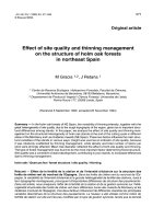
Fig. 2.1. One-stage bubble formation model in viscous liquid by Davidson and Schüler
(1960a).
The initial conditions are taken as the bubble radius ( r ' ) equal to the orifice radius ( r0 )
and with the center of the bubble in the plane of the orifice. The lift-off occurs
continuously as a natural of consequence of the growth and rise of the bubble. The
detachment is assumed to happen as the vertical distance ( y ) between the center of the
bubble and the orifice is equivalent to the final bubble radius ( r ' ).
They concluded the viscosity has a major effect on bubble size. For constant flow
condition, the surface tension has no effect other than that due to the small forces arising
from contact round the edge of the orifice. With constant gas pressure, the surface tension
has an appreciable effect on the pressure in the bubble and so to some extent governs the
flow into the bubble.
2.3.2 The models of Hayes et al. and Sullivan et al.
8