Modelling study of a container distribution system for high rise factories
Bạn đang xem bản rút gọn của tài liệu. Xem và tải ngay bản đầy đủ của tài liệu tại đây (2.02 MB, 80 trang )
CHAPTER 1
INTRODUCTION
Singapore is currently the world’s largest transshipment hub and is connected to
600 ports in 123 countries. In the year 2002, the Port of Singapore Authority (PSA),
handled 17 million TEUs (Twenty-foot Equivalent Units) [1]. More than 80% of this
volume is transshipment cargo destined for countries other than Singapore. This has
resulted in 8% annualized growth in container traffic over the past two decades and
rapid economic growth in many developing countries. To handle the ever increasing
container traffic, an entire logistics system is developed comprising of the warehouses
and freight stations, road and rail transport, ground handling equipment like straddle
carriers and gantry cranes in the port terminals, and larger container ships (in excess of
10,000 TEUs) to benefit from the economies of scale.
To meet the increased container capacity as well as logistics warehouse space, it
is inevitable that warehouses and freight stations will increase in size and more efficient
designs and container handling systems are being proposed to increase the throughput
and efficiencies. Single-storey factories and warehouses are the norm in many
countries. The container trucks arrive at the docks of the warehouses, where forklifts
are driven into the containers for the cargo loading and unloading activities. Often, the
trailer and the container will be left behind as the loading of the cargo may take up to a
day. This is inefficient, as this also requires a large tract of land for building the docks
and wide roads for the container trucks to be driven to the doorsteps of the warehouses.
1
Continuously rising land prices and limited availability of building space are
some of the reasons to build factories and warehouses skywards. Multi-storey industrial
buildings increase the usage of land resources, and this is particularly more significant
for countries such as Hong Kong and Singapore, where land is scarce. The future trend
of factories will be in the form of high-rise buildings. Material handling and
transportation economies also favor this new trend. Vertical movement in multi-storey
buildings eliminates longer, slower and costlier horizontal handling of containers in
sprawling single-storey factories. Compact multi-level design also offers advantage in
factory design construction and operation. Excavation, foundation, building and
maintenance costs are often less per square metre of usable floor space in high-rise
buildings compared to single-storey factories.
The Jurong Town Corporation (JTC) was established in 1968 to plan, develop
and manage industrial estates in Singapore. Over the last 30 years, JTC has been
conscious of the importance of optimizing the use of its industrial land. It has done so
through intensification of land use, making more productive use of land, and improving
the planning and development of the supporting infrastructure. It has also been
constantly reviewing the allocation policies for industrial and ready-built factories, and
revising the planning development of industrial estates and factories.
Singapore has reached a point in economic growth where it can no longer rely
solely on increases in labour and capital investments to fuel further growth. It has to
focus on productivity gains and innovation for greater output per unit of input [2].
Industries that operate in a multi-storey environment are better able to achieve higher
land productivity levels than those that do not. Hence, JTC has been building its
2
factories to higher plot ratios (from 1.8 to 2.5) to increase the efficiency of land use and
to encourage industrialists to go high-rise whenever possible.
These high-rise flatted factories, such as the nine-storey flatted factories located
at Woodlands East, are designed to integrate marketing, management, production,
storage and other industrial activities. They are served by cargo/passenger lifts and
loading bays, and some latest factories are designed with ramps that go all the way to
the higher floors of these buildings to enable container trucks to transport the cargo to
the sheltered loading bays at the entrance of the factory units on every level. Hong
Kong also solves land scarcity by building industrial facilities that go as high as twenty
storeys and ramps that allow vehicular access up to thirteen storeys.
Although going skywards is the solution to solving land scarcity, building such a
large vehicular ramp requires an extensive land area and large capital cost. A better
alternative system is one that delivers the containers to the various floors of a high-rise
factory by other means, instead of the existing vehicular ramp. The envisioned factories
of the future would be high-rise buildings that incorporate both the office and
manufacturing plant in a “single building”. Containers will be lifted to the various
floors and placed in the container lobby of the factory unit. The company would then
unload or load the cargo into the container. This is more efficient and economical since
less land and building cost is incurred to construct the docking areas and the vehicular
ramp. Furthermore, the empty container can be transported one day prior to loading of
the goods and no trailer will be left idling. Having the container in the container lobby
also provides the extra security compared to leaving the container in the open docks in
existing factories.
3
The main concern is on the delivery of containers to the various floors of the
high-rise factories. The final proposed distribution system must allow for the smooth
and problem-free movement of containers and reduce operating and maintenance costs.
Less land and lower capital outlay will be the foremost criteria in proposing a new
container distribution system.
This thesis is organized as follows. Chapter 2 first reviews the existing methods
of delivering containers to various floors and later proposes a new container
distribution system. Analytical and simulation studies of the proposed system are
presented in Chapters 3 and 4 respectively. Chapter 5 discusses the simulation results
and a cost analysis is performed to select the optimal crane configuration for uncertain
truck arrivals. Conclusions are drawn in Chapter 6, together with some
recommendations for further study.
4
CHAPTER 2
CONTAINER DISTRIBUTION SYSTEMS
2.1
CURRENT CONTAINER DISTRIBUTION SYSTEMS
2.1.1 Vehicular Ramp
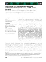
Incorporated in 1981, ATL Logistics Centre Hong Kong Ltd. (a subsidiary of
CSX World Terminals) owns and operates ATL Logistics Centre - the world's first and
largest intelligent multi-storey drive-in cargo logistics centre (Figure 2.1) [3].
(a)
(b)
(c)
(d)
Figure 2.1: ATL Logistics Centre in Hong Kong (From [3])
(a) The Main Complex
(b) Vehicular Ramp
(c) Cargo Being Loaded/Unloaded at Docks
(d) Wide Access Roads Inside Buildings
5
Conveniently located in the heart of Kwai Chung Container Terminals and within
easy reach of Hong Kong's commercial and population centres, airport and the
Mainland border, ATL Logistics Centre offers warehouse and office leasing with a full
range of cargo handling, container freight station and distribution services. ATL
Logistics Centre is made up of two multi-storey warehouses: Centre A and Centre B,
comprising of seven and thirteen storeys respectively. It consists of a three-lane (two
lanes up and one lane down) vehicular ramp to provide direct drive-in access to all
levels of the buildings. The ramp and internal loading bays are accessible for all
vehicular types including 40-ft container trucks. The Centre comprises a total floor
space of 9.4 million square feet, provides over 1,730 loading bays and handles an
average of 8,000 vehicles daily.
Similar logistics warehouses are also found in Singapore. As part of Industrial
Land Plan 21 (IP21) [4], JTC has also learnt from Hong Kong by building multi-storey
warehouses to solve land scarcity. Jurong Port (a subsidiary of JTC) not only is a key
bulk and conventional cargo gateway in Singapore, with 23 berths serving over 7,000
vessels every year, it also owns the Jurong Logistics Hub, which is Singapore’s largest
multi-storey drive-up warehouse (Figure 2.2) [5].
The Hub is a multi-storey drive-up warehouse, which allows 40-ft containers to
be trucked to every level, right to the doorsteps of customers and under all weather
conditions. Strategically located from the Port, Jurong Island, Jurong Industrial Estate
and Tuas industrial zone, the ultra-modern warehouse comprises of 118,000 square
metres of warehouse space and 6,200 square metres of office space. Jurong Logistics
6
Hub's customers include multi-national corporations and logistics providers such as
Sony, Volvo, Translink, L’Oreal and Dell Computers.
(a)
(b)
(c)
(d)
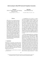
Figure 2.2: Jurong Logistics Hub
(a) The Main Complex
(b) Vehicular Ramp
(c) Large Turning Radius
(d) Container Left at Dock
7
JTC has also adopted a similar drive-in concept for its stack-up factories to
optimize land usage. Named Woodlands Spectrum (Figure 2.3) and located in
Woodlands East Industrial Park, these high-rise facilities offer ground-floor
convenience (through a large ramp for container trucks), private loading areas and car
parks. The ramp has to be wide enough to accommodate the turning radius of 40-ft
trucks and large access roads have to be constructed for easy manoeuvere to reach the
units at different levels [6].
(a)
(b)
(c)
(d)
Figure 2.3: Woodlands Spectrum
(a) Overview of One Unit
(b) Interior of Vehicular Ramp
(c) Wide Access Roads
(d) Unloading/Loading Dock
8
Large capital cost is required to construct such a container delivery system and
also a large plot of land is required for the building of the vehicular ramps and wide
roads. Figures from JTC show that the ramp amounts for one-third ($600 million) of
the total construction cost (for Woodlands Spectrum). It is ironical that what causes
factories to move skywards (to optimize land space and cost) in the beginning ends up
with a design using a large plot of land for the vehicular ramps and wide roads, and
incurs a large capital cost. A solution to this would be a new system of delivering the
containers to the various floors of the multi-storey factories without using a large
vehicular ramp.
2.1.2 Container Hoisting Crane
One of the key objectives of this research is to propose a new and innovative
method of delivering the containers to each and every unit’s doorsteps without utilizing
the direct drive-in model of the vehicular ramp. Since the item being transported is the
20-ft and 40-ft ISO containers, the handling methods at maritime terminals may
provide suitable alternatives. Using cranes to transport the containers is a tried-andtested efficient distribution method and the crane design can be incorporated in the
vertical hoisting of the containers to various floors of the buildings. The small ground
area required, the low dead weight and the resulting low load on the building are some
of the advantages that illustrate the expediency and economy of using container cranes.
In fact, container cranes had already been implemented in many high-rise
factories and warehouses around the world. A customer list (Table 2.1) obtained from
Mannesmann Demag (a company that manufactures and installs container hoists)
shows that Hong Kong has many high-rise factories and warehouses that utilize
container cranes to deliver the containers to the various floors.
9
Table 2.1: Customer List from Mannesmann Demag
Reference List (Container Hoist Installations)
No. of storeys
Year of
Customer
Country
served
Construction
(plus ground floor)
Kowloon Wharf
Hong Kong
11
1972
Kowloon Wharf
Hong Kong
11
1972
Kowloon Wharf
Hong Kong
15
1975
Kowloon Wharf
Hong Kong
14
1975
Taikoo
Hong Kong
9
1977
Tai Sang Land
Hong Kong
9
1980
Development
Singapore
Singapore
12
1981
Warehouse
Singapore
Singapore
12
1981
Warehouse
Swire Bottlers
Hong Kong
5
1981
Tai Sang Land
Hong Kong
17
1981
Development
Tina’ Enterprise
Hong Kong
14
1982
Southwinds Land
Hong Kong
15
1982
& Investments
The machine room with the hoist and electrical equipment, the hoist shaft outside
or inside the building with horizontal travel tracks into the lobbies, the vertical
guidance system, the spreader and the various container positions in the lobby, all form
a single unified system. Each floor has a control panel from which the operator starts
and monitors all functions for the particular lobby. Display panels provide information
on the operations currently being carried out and on those that have been completed.
The container truck delivering the container will first position itself underneath
the hoisting crane. The crane, guided by vertical beams, will be lowered and the selfadjusting spreader will then lift up the container to the pre-selected level. Selection of
the optimum lifting speed is dependent on the number of floors and the number of
containers to be handled per hour. Once it has been lifted to the level, the spreader will
10
be transferred horizontally via tracks and deposit the container at the lobby. Thereafter,
the loading or unloading of cargo can be carried out with forklifts. Such a system offers
better security than leaving the container in the docking area. Figure 2.4 illustrates the
sequence of a container being delivered to a unit in a high-rise warehouse in Taikoo,
Hong Kong.
(a)
(b)
(c)
(d)
Figure 2.4: Sequence of Delivering Container to a Unit
(a) Truck Positioned Underneath Spreader
(b) Container Being Lifted to Pre-selected Level
(c) Container Being Transferred Horizontally Into Lobby
(d) Loading and Unloading of Cargo via Forklift
11
A high-rise factory at River Valley Road employs the same distribution system as
that of Taikoo, Hong Kong. However, the factory utilizes two container hoists, each
serving one face of the building. Similarly, the truck will be positioned underneath the
spreader, and once in position, the spreader will be lowered to hoist up the container to
the selected level, which is then transferred horizontally into the lobby. Each hoist can
only handle containers meant for factory units located on the same side of the building.
No crossover of containers is possible. This creates a problem during the breakdown of
the hoisting cranes, as this will affect the whole container distribution system for that
building. The hoisting service for that building is virtually down whenever repair or
maintenance work is required. Figure 2.5 shows the crane hoists used in the factory.
(a)
(b)
Figure 2.5: Crane Hoists Used to Lift Containers
(a) Double Cranes
(b) Close-up View of Crane
12
Although container hoisting cranes have already been implemented in many
multi-storey factories around the world, they still have deficiencies. Although the
system of using hoisting cranes has freed up land and capital that would have been used
for the vehicular ramp, the vertical distribution system still contains some deficiencies,
such as the disruption to the factory when the cranes fail.
2.1.3 Automated Storage and Retrieval System (AS/RS)
In recent years, the AS/RS has had an important impact on storage and
warehousing operations. These high-rise storage modules are becoming increasingly
popular and have been successfully integrated in many manufacturing and distribution
processes and warehousing enterprises around the world dealing with numerous items
in large volumes. AS/RS is an attractive solution to limited storage space, high labour
costs, shorter as well as reliability in cycle times, random access requirements and realtime material identification and tracking capability.
Recently, much research has also been reported on the feasibility of
implementing AS/RS for maritime container terminals [7-9]. Faced with substantial
increases in container traffic, limited land availability, larger vessels and the need to
become cost competitive, this high density storage system will play an important role in
the future success of many container terminal activities. It is believed that the current
container handling processes result in the misallocation of expensive and scarce land
resources at terminal sites, wastage of capital in inventory, longer waiting time of
trucks and ships, and a larger fleet size of yard-trucks. Implementing AS/RS in a
container terminal would improve terminal operations.
13
Ioannou et al. [9] published an extensive report for the Center for Advanced
Transportation Technologies of the University of Southern California, which provides
an engineering evaluation and quantitative assessment of the performance of existing,
emerging and conceptual cargo handling technologies for terminal operations, and
proposes three automated container terminal concepts employing advanced
technologies. One of the proposed designs is an automated container yard using AS/RS.
Three high-rise storage and retrieval systems are proposed, namely the Seaport
Container Storage Systems (in association with Transact), Earl’s Computainer and
Krupp’s Fast Handling System.
Figure 2.6: Physical Model of Container Storage System by Seaport (From [9])
14
The Seaport Container Storage System (Figure 2.6) is based on the Transact
design of automated air cargo handling system employed in some airports. It adopts a
proprietary design of double deep racks, where each rack is ten levels high, with four
storage positions on each level. An automatic stacker crane called Elevating Transfer
Vehicle (ETV) interfaces horizontally and vertically with the storage cells. A shuttle
mounted on the ETV stores and retrieves containers from the storage cells on each side
of the ETV aisle. An automatic overhead crane with a 40-ft spreader provides the
means to receive and deliver containers to and from the horizontal material handling
systems (trucks, transfer cars or AGVs).
Figure 2.7: Earl’s Computainer (From [9])
Earl’s, a leading manufacturer of container spreader bars, has built a full-scale
prototype of an AS/RS called Computainer (Figure 2.7). The Computainer is a multistorey steel structure with a small number of storage cells. Less than four acres of land
is required for 2,000 40-ft containers and related access and truck queueing areas.
15
Multiple access bays are provided for rapid truck turn around. The Computainer
includes an integrated hoist transfer system based on proven technology. Its mechanical
design and operational simplicity account for its attractiveness as a viable storing
solution for container terminals.
Figure 2.8: Prototype of Krupp Fast Handling System (From [9])
Krupp, a German manufacturer of marine cranes and mining material handling,
has developed an automated system design specifically for intermodal rail terminals
(but can be adapted for marine terminals) known as “Krupp Fast Handling System”. A
prototype (Figure 2.8) of this concept has been installed at the Duisburg-Rheinhausen
terminal. Each module comprises a set of end and middle pickup/deliver stands, a highrack handling device and channeling vehicles. The high-rack handling device moves
along the transverse aisle on guide rails and mainly serves to transport the loading units
vertically to the storage levels.
16
By the year 2020, it is projected that the amount of cargo transferred between
container terminals will be doubled. The scarcity of land in many areas makes it almost
impossible for many terminals to respond to this increasing demand by expanding their
yard facilities. The high-density storage AS/RS can be built on a small piece of land
and capacity is increased by adding more floors. The high productivity of the AS/RS
lies in its capability to access any container within the storage structure. The high
productivity and high storage capacity on a small piece of land, make it attractive to
employ the AS/RS concept for the proposed container distribution system for high-rise
factories.
17
2.2
PROPOSED CONTAINER DISTRIBUTION SYSTEM
2.2.1 Description of the Proposed Container Distribution System
The design of the proposed container distribution system is based on the concept
of utilizing overhead cranes currently employed in port operations. Instead of using the
hoisting cranes in one fixed location, the proposed design uses automated overhead
cranes that are able to travel to different column sections (different factory units). This
design provides backup options in the event a crane malfunctions, in which case, it can
be pushed to a free space between the columns. The other remaining cranes can then be
deployed to service the factory.
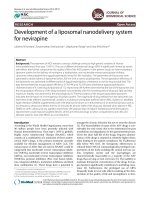
The overhead crane runs on top of two buildings that are about 15 metres (three
vehicle lanes) apart and this allows the trucks to have easy manoveure. The spreader is
able to travel across the span of the buildings as well as to cross over to either building
to handle the containers meant for different columns. Figure 2.9 shows the proposed
container distribution system on a factory consisting of two columns and three storeys.
(a)
(b)
Figure 2.9: Proposed Container Distribution System
(a) Overview of the Factory
(b) Innerview of the Factory
18
The trucks will first be positioned in different column sections depending on
where the factory units are located. For safety reasons, the containers can only be
hoisted or lowered vertically. This means that the overhead crane will first travel to the
designated column section before hoisting up the container vertically. Wind gusts can
impose a considerable external load on the hanging container, causing it to sway and
knock against the building walls. To eliminate swaying, vertical guides are installed for
the spreader.
Figure 2.10: Container Lobby
Once the crane has latched onto the container and hoisted to the selected level,
the lobby platform will be extended out to receive the container. The extensible
platform moves on steel wheels and is operated by hydraulic pistons. The platform uses
flangeless track wheels and travels on tracks with flat head while guided by lateral
guide wheels. This is to prevent skewness of the platform and ensure it moves in a
straight path. The travel tracks for the platform are spaced 13 metres apart to allow the
crane to move a 40-ft container (or two 20-ft containers) vertically between the tracks.
Figure 2.10 shows the design of the container lobby.
19
The design of the container lobby is for housing one 40-ft or two 20-ft containers.
The self-adjusting spreader allows the crane to pick up different types of containers.
The crane can be equipped with a twin-lift spreader to hoist up two 20-ft containers
together. The width of the lobby can also be increased to accommodate two 40-ft
containers side by side (lengthwise) if the factory requires this. There are doors on both
sides of the lobby to solve the container orientation problem, so that the cargo can be
loaded or unloaded in either direction, depending on the position of the container.
The advantage of this proposed container distribution system is the availability of
more loading and unloading bays compared to the single hoisting system at high-rise
factories in Taikoo, Hong Kong and River Valley, Singapore. An integrated
computerized system performs the following functions:
•
The identification of the arriving truck.
•
The positioning of the overhead crane in advance.
•
Latching on and lifting of the container to the various floors.
•
Lowering it onto the extended platform.
The factory has a ground control station, from which an operator is able to initiate and
monitor all operations. The interested reader is referred to [10] for an extensive
discussion on the operations of the various systems (such as automated overhead
travelling crane, smart spreader, container positioning system) employed in the factory.
2.2.2 Operation of the Proposed Container Distribution System
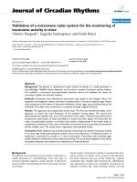
The proposed factory consists of two five-storey buildings, each with nine
columns, giving a total of ninety units. The two buildings are referred to as Block A
and Block B and the nine columns are numbered Column 1 to Column 9. There is a
20
common waiting area for trucks queueing for service when the cranes are not available.
A number of cranes travel on top of the buildings to handle the containers meant for
each column. Figure 2.11 shows a schematic diagram of the proposed factory.
The operation of the Factory consists of inflow and outflow processes. For the
inflow process, the loaded truck arriving at the factory is identified for its destination,
with details such as the Block Type, Column No., Unit No. and the Type of Operation
(loading or unloading). If the crane is available, the truck will proceed to the column;
otherwise it will be directed to a waiting area. The crane assigned to that column then
starts unloading the container. After the container has been transferred to the designated
lobby, the truck leaves the factory and the next truck in queue proceeds to be serviced
by the crane. For the outflow process, a similar sequence of events is applied. In this
instance, the empty trucks will arrive to be loaded with the containers from the various
units. Figure 2.12 shows the flowchart of the operation of the factory.
Block A
1
2
3
4
5
6
Crane 1
1
2
7
8
Columns of
factory units
Crane 2
3
4
5
6
7
9
8
9
Block B
Legend
Crane Movements
Figure 2.11: Schematic Picture of Factory (Top View)
21
Truck arrives
at factory
Truck identified to obtain information on
Arrival Time, Block Type, Column No.,
Unit No., Type of Operation (unload or
load)
Proceeds to column to begin
service OR remains in
waiting area if crane is busy
Truck queues
at waiting area
Truck leaves the
factory after service
Figure 2.12: Flowchart of Operation of Factory
The overall aim of the study is to investigate whether the proposed factory, its
individual components and operating logic would interact efficiently to produce an
optimal performance. For this purpose, performance parameters such as the number of
cranes required, the assignment of cranes, the average delay encountered by the trucks
in queue and the size of the waiting area for the trucks must be determined. The inverse
relationship between the number of resources and queueing time requires the
“optimization” of the number of cranes to be used in the factory. More cranes may
result in reducing waiting times, but may increase the overall cost of the proposed
factory. Estimates for the queueing times and crane utilization will help in the decision
of identifying the appropriate number of cranes to be used and how they are assigned to
service the trucks.
For the factory in consideration (Figure 2.11), the number of cranes can range
from one to a maximum of nine. However, the extreme values are not desirable because
a single crane does not allow for any backup during breakdowns and using nine cranes
is a waste of resources as the cranes would be idle most of the time. Another important
research issue is crane assignment. Since the number of cranes is less than the columns,
22
it is essential to assign the cranes effectively to the columns. In this research,
configurations of using two, three and four cranes are examined. The main concern is to
choose the appropriate number of cranes in order to achieve acceptable queueing times
for service and crane utilizations. A minimum of two cranes is selected to ensure that
the Factory’s operation is not hindered when one of the cranes breaks down. Figure
2.13 shows the crane configurations using two, three and four cranes.
Denotes crane
Denotes columns
Denotes allocation flexibility
1
2
1 2 3 4 5 6 7 8 9
1 2 3 4 5 6 7 8 9
(a)
1
1
2
2
3
1
1
4
2
2
3
3
5 6
(b)
7
3
4
1
8
9
1
4
5 6
(d)
7
8
2
2
3
1
9
1
4
2
2
3
3
5 6
(c)
7
3
4
5 6
(e)
8
9
8
9
4
7
Figure 2.13: Various Crane Configurations
(a) Two-crane Configuration
(b) Three-crane Configuration Type I
(c) Three-crane Configuration Type II
(d) Four-crane Configuration Type I
(e) Four-crane Configuration Type II
23
Crane configurations are classified into groups based on the different number of
cranes employed, each of which consists of a few configurations depending on the
flexibility of assigning the columns to the cranes. With full allocation flexibility, the
average waiting time may be reduced. However, in the factory, the cranes are
constrained such that they may not cross each other. In the context of machine
allocation [11,12], it has been shown that the performance of a system with slight
flexibility is almost equal to that with full routing flexibility. In the next chapter, the
performance of the factory under different crane configurations and truck arrival rates
is analyzed.
24
CHAPTER 3
ANALYTICAL STUDY OF PROPOSED CONTAINER
DISTRIBUTION SYSTEM
Queueing arises whenever there is more demand for service than there is capacity
for service available. This could be due to a shortage of service facilities or it is not
feasible both economically and physically in terms of space to provide the level of
service that eliminates waiting. To provide the adequate level of service, it is necessary
to determine the customer’s waiting time in the queue and the number of customers
waiting in queue.
Queueing theory was developed to provide models that give insights to how
systems behave when attempting to provide service for randomly arising demands.
Many applications of the theory have been well documented in the literature of
probability, operations research, management science, and industrial engineering. Some
examples are traffic flow (vehicles, aircraft, people, communications), scheduling
(patients in hospitals, jobs on machines, programs on a computer), and facility design
(banks, post offices, amusement parks, fast-food restaurants) [13-16].
The purpose of the models is to develop mathematical equations of the
performance measures (average waiting time as a function of customer arrival rate) for
different configurations (different arrival and service patterns, number of servers and
server configuration and queue organization). The performance measures provide an
important indicator on how well the alternative configurations meet the system
objectives. There are three types of system responses of interest. They are the average
waiting time a typical customer has to endure, the average number of customers waiting
and the idle time of the servers. The task of a queueing analyst is generally one of two
25