Related motors and actuators
Bạn đang xem bản rút gọn của tài liệu. Xem và tải ngay bản đầy đủ của tài liệu tại đây (685.42 KB, 12 trang )
Chapter 9
Related motors and actuators
The previous chapters have considering the motors and drives that are normally
used within the range of applications that have been identified in Chapter 1. However, there are a number of specialist or unconventional motors that can and are
being used in an increasing number of applications. These motors may be selected
for a wide verity of reasons, both technical and commercial. This chapter considers
a number of theses motors and their associated controllers, therefore allowing the
design engineer to have an overview of all available technologies. In this chapter
the following motors are considered:
• voice coil actuators
• limited-angle torque motors
• piezoelectric motors
• switched reluctance motors
• shape memory alloy, SMA.
While these motors currently have specialist niches in servo drive applications, a
range of exciting motors are currently being developed based a wide range of technologies, including electrostatic and micro electromechanical (MEM)technologies,
and these will no doubt find their way into more general use over time (Hameyer
and Belmans, 1999). Currently this technology is still the research stage, but the
appUcations currently being explored are significant and challenging, and for example include the manipulation of a single DNA molecule (Chiou and Lee, 2005).
9.1 Voice coils
Voice coils or solenoids are ideally suited for short linear (typically less than 50
mm) closed-loop servo applications and both operate on similar principles. In a
voice coil, the actual coil moves, while in a solenoid, the iron core moves. Typical
235
236
9.1. VOICE COILS
Soft iron core for flux
return
Magnet
Tubular coil
Output
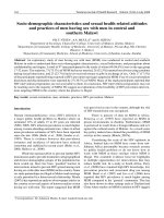
Figure 9.1. The cross section of a voice coil; the dimensions of the air gap has
been exaggerated.
positioning appHcations include direct drives on pick and place equipment, medical
equipment, and mirror tilt and focusing actuators. In addition voice coils can also
be used in appHcations where precise force control is required, due to the linear
force versus current characteristics.
A voice coil is wound in such a way that no commutation is required, hence a
simple linear amplifier can be used to control the actuator's position. The result is
a much simpler and more reliable system. Voice coils have a number of significant
advantages including small size, very low electrical and mechanical time constants,
and low moving mass that allows allows for high accelerations, though this depends
on the load being moved.
Voice coil actuators are direct drive, limited motion devices that utilise a permanent magnet field and coil winding (conductor) to produce a force proportional
to the current applied to the coil. These non-commutated electromagnet devices
are used in Hnear (or rotary) motion applications requiring a linear force output,
high acceleration, or high frequency actuation.
The electromechanical conversion mechanism of a voice coil actuator is governed by the Lorentz force principle; which states that if current-carrying conductor
is placed in a magnetic field, a force will result. The magnitude of the force is determined by the magnetic flux destiny, B, the current, z, hence for a winding of A^
turns, the resultant force is given by
F = BLiN
(9.1)
In its simplest form, a linear voice coil actuator is a tubular coil of wire situated
within a radially oriented magnetic field, as shown in Figure 9.1. The field is produced by permanent magnets embedded on the inside of a ferromagnetic cylinder.
CHAPTER 9, RELATED MOTORS AND ACTUATORS
237
The inner core of ferromagnetic material is aligned along the axial centreline of the
coil, and joined at one end to the permanent magnet assembly, is used to complete
the magnetic circuit. The force generated axially upon the coil when current flows
through the coil will produce relative motion between the field assembly and the
coil, provided the force is large enough to overcome friction, inertia, and any other
forces from loads attached to the coil. For a specific operating displacement of the
actuator, the axial lengths of the coil and the magnet assemblies can be chosen such
that the force vs displacement curve can be optimised, resulting in the reduction of
force at the mid-stroke force being limited to less than 5% of the maximum force.
The sizing and selection of a voice coil actuator is no different from any other
Unear application, the process defined in Section 3.8.4 can be followed.
9.2 Limited-angle torque motors
Limited-angle torque motors are a range of special-purpose motors that are capable
of giving controllable motion up to ±90° from their rest position. While brushless
motors, as discussed in Chapter 6, have many benefits, they have the penalty of
being relatively expensive and complex, if only a limited range of motion is required. The requirement for a limited range of movement can be found in many
applications, including the operation of air or hydraulic servo-valves and oscillating
mirrors. In addition, their inherent reliability of operation makes a limited-angle
torque motors an ideal solution for applications where limited actuation is critical, for example in spacecraft latches, where the only previous solution was to use
pyrotechnics.
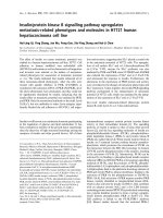
The basic construction of a limited-angle torque motor is shown in Figure 9.2.
While they are broadly similar to brushless d.c. motors, the limited-angle torque
motor is a single-phase device, which eliminate the need for the commutation logic
and the three-phase power bridge that are found in multiphase machines. The
torque motor's winding can be wound in conventional slots or as a toroid over
a slotless stator. The rotor in a limited-angle torquer incorporates one or more
magnets. The slot-wound limited-angle torque motor has a number of advantages
over toroidally wound motors; in particular they have better thermal dissipation
and a higher torque constant. However, because of the presence of slots, the output
torque ripple and hysteresis losses are greater. The torque ripple can be considered
to be zero with toroidally wound motors due to the non-varying reluctance path and
the large air gap. In addition the slot-wound limited-angle torque motor exhibits a
higher motor constant. Km, than the corresponding toroidally wound motor, due
to the larger number of conductors that are exposed to the magnetic field.
Cogging is essentially zero in toroidally wound limited-angle torque motor,
a result of a non-varying reluctance path and relatively large air gap. Toroidally
wound armatures, moreover, are typically moulded onto the stator, which protects
the windings from damage and holds them in place.
In the selection of a limited-angle torque motor for an application, a number of
238
92. LIMITED-ANGLE TORQUE MOTORS
gtator
Stator
(a) Slotted armature.
(b) Toroid armature.
Figure 9.2. Internal construction of limited angle torque motors.
Torque
Torque
+45^
-45°
Rotor position
0°
Rotor position
+45
(b) Toroid armature.
(a) Slotted armature.
Figure 9.3. Torque-position characteristics for a limited angle torque motor.
parameters shall be considered, including:
• Peak torque. As in a conventional motor, this is the torque which is developed at the rated current.
• Excursion angle. This is the maximum angle that the rotor can move from
the peak-torque position, and it is normally expressed as a plus/ minus value.
Figure 9.3 shows typical characteristics for a slot-wound and a toroidally
wound motor. In the latter case, the constant-torque region should be noted.
Limited-angle torque motors are currently available in ratings from 7 x lO""^
to 0.142 N m, with excursion angles between ±18° and ±90°.
As limited-angle torque motor are single-phase motors, they are easily controlled by single-phase bipolar PWM amplifiers which are identical to those used
with brushed d.c. motors. In certain applications, a linear amplifier could be used
to increase the bandwidth and to reduce the electrical noise. The limited-angle
torque motor produces torque through a rotation angle determined by the number
of motor poles. Current of one polarity produces clockwise torque, and vice versa.
Manufacturers generally provide a theoretical torque versus shaft-position curve.
Typically, the characteristic curve for a slotted armature limited-angle torque motor
is represented by a cosine function; that is
ON
T = T„ cos-
(9.2)
CHAPTER 9. RELATED MOTORS AND ACTUATORS
239
Torque
Load
torque
—Usable displacementRotor position
Figure 9.4. The restriction in usable displacement of a limited-angle torque motor
as a function of load torque.
where 6 is angle of rotation, A^ is number of poles, and Tp is the peak torque. The
general torque characteristic for toroidally wound motors can be represented by a
similar curve, but it may also have aflattop.
The selection of a limited-angle torque motor for an application follows an
identical route to that of any motor. The process starts with the determination
of the application's constraints and of the performance which is required. Once
the torque, and the angle over which it is to be applied, has been determined, the
suppliers data must be referred to. As the torque-angle characteristic of limitedangle torque motor is sinusoidal, care must be taken to ensure that these devices
can produce the required torque throughout the proposed actuation angle, as shown
in Figure 9.4.
9.3 Piezoelectric motors
Many specialist applications require motors of extremely high resolution, for
example, micropositioning stages, fibre-optic positioning, and medical catheter
placement. One motor that can meet these requirements is the piezoelectric motor. When compared to a conventional motors and its associated power train, the
piezoelectric motor has a faster response times, far higher precision, inherent brake
capability with no backlash, high power-to-weight ratio, and is of smaller size.
The operation of this motor is based on the use of piezoelectric materials where
a material is capable of being deformed by the application of a voltage. A range
of materials such as quartz (Si02) or barium titanate (BaTiOa) exhibit the piezoelectric effect. However in motors normally mass-produced polycrystalline piezoelectric ceramic is used. To produce a suitable ceramic, a number of chemicals
are processed, pressed to shape,fired,and polarised. Polarisation is achieved using
high electricfields(2500 V/mm) to align material domains along a primary axis. In
Figure 9.5(c), a voltage is applied to a piezoelectric crystal to produce a displacement. If the material has a displacement constant of 5(X) pm V~^ the application
240
9.4. SWITCHED RELUCTANCE MOTORS
f f \\/,\\
M' \
\ /
(b)
(a)
(c)
Figure 9.5. The characteristic of a piezoelectric material, (a) shows domains in
the the unpolarised material, which align when polarised, as shown in (b). The
application of a voltage causes axial displacement, d.
of 200 V, will produces an axial displacement of 0.1 fim.
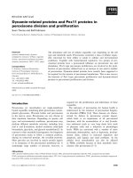
Figure 9.6 shows the basic concepts of a piezoelectric motor. Two piezoelectric crystals are preloaded against a flat wear surface, by way of the motor shoe,
to produce a normal contact force. The friction is important in the design of the
motor, since the friction force is used to translate the motion of the piezoelectric
ceramic into the motor's output. As a positive sinusoidal voltage waveform is applied which increase its thickness, the axial motion imparts a frictional force along
the wear strip. When the drive voltage goes negative, the same crystal thickness
contacts. This action creates a separation between the motor shoe and the wear
strip, allowing the motor to return to its original position without dragging the
wear strip backward. As the drive voltage swings positive again, the crystal stroke
cycle repeats and the wear strip moves another incremental step to the left.
9.4 Switched reluctance motors
While not originally designed for high-performance servo applications, the
switched reluctance motor is making inroads into this area, due to the availability
of low-cost digital signal processing. The switched reluctance motor is particularly
suitable to a wide range of applications due to the robustness of the mechanical and
electrical design.
In a reluctance machine, the torque is produced by the moving component moving to a position such that the inductance of the excited winding is maximised. The
moving component is typically the machine's rotor - which can be either internal
or external depending on the design - or a linear component in the case of a linear
CHAPTER 9. RELATED MOTORS AND ACTUATORS
^
^
Preload
Spings
n
(a) The motor at rest (Vs — 0): the motor head is
preloaded against the wear surface.
ES^
Preload
Spings
D
(b) On excitation of the piezoelectric actuator (V^ > 0),
the head moves against the wear surface, moving the
wear surface.
Gap
^
^
Preload
Spings
(c) Excitation of the piezoelectric material (Vs < 0),
releases the actuator for the wear surface, allowing the
actuator to return to its initial position.
Figure 9.6. The operation of a piezoelectric motor.
241
242
9.4. SWITCHED RELUCTANCE MOTORS
indings
Stator
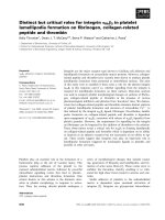
Figure 9.7. The cross section of a switched reluctance motor.
reluctance motor.
The switched reluctance motor is topologically and electromagnetically similar in design to the variable-reluctance stepper motor discussed in Section 8.1.2.
The key differences lie in the details of the engineering design, the approach to
control, and hence its performance characteristics. The switched reluctance motor
is operated under closed loop control, with a shaft mounted encoder being used
to synchronise the phase currents with rotor position. In comparison the variablereluctance stepper motor is operated open loop.
The operating principles of the switch reluctance machine can be considered by
examination of Figure 9.7. The number of cycles of torque production per motor
revolutions is given by
(9.3)
S = mNr
where m is the number of phases, and A^^ the number of phases. A more detailed
analysis of the motor can be found in Miller (2001). The voltage equation for
a single phase can be calculated in a similar fashion to that used for a brushless
motor
V^
Ri-^
~dt
Ri + UJr
d^p
(9.4)
where v is the terminal voltage, i is the phase current, ip is the flux-linkage in
volt-seconds, R is the phase voltage, L is the inductance of the phase winding, 9
CHAPTER 9. RELATED MOTORS AND ACTUATORS
243
is the rotor position and Um is the rotor's angular velocity. This equation can be
expanded to give
v = Ri + iUm~^
=Ri + L—+ uJmi-jK
(9-5)
du
dt
du
In a similar fashion to a d.c. brushed motor it is useful to consider the terminal
voltage V as the sum of three components: the resistive voltage drop, the voltage
drop due to the inductance and rate of change of current, and the back e.m.f. term,
e
e = u:J^
(9.6)
From equation 9.5 it is possible to calculate the instantaneous electrical power, vi,
as,
^9
^ di
vi = Ri^-\-Li—+
.9 dL
i^rrT-TT:
di
dB
which allows the rate of change in magnetic energy to be calculated:
,_ _^
(9.7)
The electromagnetic torque generated by the motor can therefore be determined
from the instantaneous electrical power minus the resistive voltages drops due and
the rate of change of magnetic stored energy:
Te =
^^-^^
(9.9)
The rate of change of inductance as a function of rotor position is one of the design
parameters of the switched reluctance machine. From equation 9.9 it is clear that
the torque does not depend on the direction of current flow, however the voltage
must be reversed to reduce the flux-linkage to zero. A suitable power circuit for
a single winding is shown in Figure 9.8. It is immediately clear that this circuit
is far more robust that the conventional PWM bridge shown in Figure 6.5(a), as a
Une-to-Une short circuit is not possible.
The circuit shown in Figure 9.8 is capable of operating the motor as either a
motor or a generator, as vi can either be positive or negative, and the power flow
is determined by the switching pattern of the power bridge relative to the rotor's
position. A block diagram of a suitable controller for a basic switched reluctance
motor is shown in Figure 9.9. It is recognised that although this type of drive
is simple, and gives adequate performance for speed control, it is incapable of
providing instantaneous torque control as required by a servo or similar application.
244
9.4. SWITCHED RELUCTANCE MOTORS
q"
QlpH
H—
: SRM
- Phase
1^
H
r^
^
Q2
H—
Figure 9.8. A single phaseleg as used in a switched reluctance motor. The current
direction is determined by Ql and Q2, with the respectiveflywheeldiodes.
Velocity
Controller
1
,
PWM
Controller - 1 /
<
Power
Bridge
1 '^.nM
1 onivi
Vr~
/F^
\r
^
i
Cur rent
fnPTJ hark
Commutation
Control
Position feedback
Speed feedback
Figure 9.9. A typical controller for a switched reluctance machine operating under
velocity control.
CHAPTER 9. RELATED MOTORS AND ACTUATORS
245
To achieve a performance similar to a conventional servo-drive, commutation
as a function of rotor position has to be replaced by a control strategy that produces
the desired total motor torques by controlling the individual phase currents. The
approach taken is very similar in principle to that used to control the a.c. induction
motor as discussed in Section 7.3, and in the paper by Kjaer et al. (1997). It is
clear that the switched reluctance machine is a very robust machine, that could
offer the designer of high performance application an additional choice in the drive
selection. While the switched reluctance machine is becoming widely used in high
speed applications is has not been seen in the high performance position control
application.
9.5 Shape-memory alloy
Shape-memory alloy (SMA) materials have the unique ability to return to a predetermined shape when heated, leading to their uses in a wide range of applications, particularly when micro-actuation is required. This property arises due
to a reversible crystalline phase transformation that occurs between the low temperature martensite and high temperature austenite phases. Although the phases
have the same chemical composition and atomic order, the two phases have different crystallographic structures. Austenite has a body-centered symmetric structure
that exists at high temperature, while martensite has a low symmetric monoclinic
structure that stabilises at relatively low temperature (Jones, 2(X)1, pl48). When
an SMA is cooled from a high temperature, the material undergoes a martensitic
transformation from the high temperature austenite. Since the bond energy in the
martensite is low, this phase can be easily deformed. In martensite, even after removal of the stress, the strain remains. This residual strain can be recovered by
heating the material to the austenite phase, which causes the SMA to return to the
original shape. This response is referred to as the shape memory effect. During
the martensite-austenite transformation, the SMA exhibits a large force against
external resistances.
Position control system using shape-memory alloy wire actuators with electrical resistance feedback has been used in a large number of applications (Ma et al.,
2(X)4). A 0.5 mm diameter nickel-titanium alloy (NiTi or Nitinol) wire can lift
as much as 5 kg , which is associated with a 5% length recovery. As shown in
Figure 9.10, a SMA actuator consists of a length of wire that is preloaded. The
applied voltage will heat the wire, hence controlling its length. This illustrates the
problems with this type of actuator; the cooling of the wire depends on the ambient
temperature, and hence its dynamic performance is poorer than other actuators, but
this is more than made up for by its size and simplicity. This high strain property
of SMAs offers great potential as actuators in a variety of different applications
ranging through micro-robot manipulation, aircraft wingshape control, and microsystem precision control, (Zhang et al., 2004; Ikuta et al., 1998). In all these appHcations, precise regulation of the actuator is requrired, which can be undertaken by
246
9.6. SUMMARY
Shaped
memory
alloy wire
Output via
crank
Figure 9.10. The use of a shaped-metal-alloy wire as part of an actuator. The
voltage across the wire, and the current through the wire which gives rise to wire
heating, is from the output of a conventional position control loop.
controlling the temperature of the wire within a closed loop controller.
9.6
Summary
This chapter has discussed a number of current and future drive systems, which
have unique properties. These drives and actuators will give the designer systems
with unique characteristics that can be exploited as required.