Electric motors and drives technical manual 2010 edition
Bạn đang xem bản rút gọn của tài liệu. Xem và tải ngay bản đầy đủ của tài liệu tại đây (14.26 MB, 346 trang )
2010 Edition
Electric Motors & Drives
Technical Manual
Through the initiative of:
International Copper Association
–
South East Asia
Institute of Integrated Electrical Engineers of the Philippines, Inc.
iii
P R E F A C E
This publication deals primarily with small and medium
-
sized induction
motors
which are the most
common type of alternating current motor.
They are internationally standardized and are efficiently manufactured in
long produ
ction runs. The combination of new materials and more
sophisticated methods for calculation, design and production have made
the modern three
-
phase induction motor a robust and reliable prime
mover.
This publication was made possible through the initiativ
e and support of
the International Copper Association
–
South East Asia and
administered, executed, and implemented by the Institute of Integrated
Electrical Engineers of the Philippines
A
ll information and data contained in this
publication
is
believed t
o be
reliable, but all recommendations or suggestions are made without
guarantee. Furthermore, suggestions for use of material supplied shall
not be
construed as a recommendation or inducement to violate any law
or infringe any
patent.
iv
v
Table of
Contents
Section
Title
Page
Motor Specifications
1.
1
Nameplate
1
1.
2
Insulation Class
3
1.3
Enclosure Type
1
1
1.4
Temperature
C
lass
19
1.5
Mounting
3
0
1.6
Manufacturer’s Identification Number
51
1.7
Te
rminal Markings
55
1.8
Motor Design
6
7
1.9
Types of
D
uty
7
6
General Characteristics
2.
1
System Nominal Voltage
103
2.
2
Voltage
104
2.
3
Power Factor
112
2.
4
Efficiency
113
2
.5
Speed
118
2
.6
Vibration Characteristics and Balancing
119
2
.7
Bearings
1
41
2
.8
Torque
1
70
Asynchronous Motor Starting Systems
3
.1
Starting Methods
17
5
3
.2
Single
-
phase
M
otor
S
tarting
18
7
Motor Protection and Coordination
4
.1
Motors
P
rotection
1
93
4
.2
Protection
A
gainst
S
hort
C
ircuits
19
4
4
.3
Protection
A
gainst
O
ver
load
203
4
.4
Multifunction
R
elays
2
12
4
.5
Motor
C
ircuit
B
reakers
21
5
Motor Starter Co
-
ordination
5.1
Concepts
21
9
5.2
Solutions
2
20
5.3
Motor Overload Protection
22
9
5.4
Terminology
2
41
vi
Motor Efficiency
6
.1
Repair
-
Replace Decision Mo
del
24
6
6
.2
Premium Efficiency Motors
2
62
Installation, Testing, and Maintenance
7
.1
Installation and
M
aintenance
2
73
7
.2
Description of Routine Tests
30
9
7
.3
Recommended Winding Tests
3
21
7
.4
Other Tests
3
22
7
.5
Motor Starting Capabilities and Co
nsiderations
3
23
7.6
Maintenance and Reliability
32
8
7.7
Maintenance Programs
3
32
7.8
Machinery Condition Monitoring
33
4
7.9
Maintenance Planning
33
8
1
Motor Specifications
1.1
Nameplate
Motor standards are established on a country by country basis.
Fortunately though, the standards can be grouped into two major
categories: NEMA and IEC (and its derivatives).
In North America, the National Electric Man
ufacturers Association
(NEMA) sets motor standards, including what should go on the
nameplate (NEMA Standard MG 1
-
10.40 "Nameplate Marking for
Medium Single
-
Phase and Polyphase Induction Motors").
In most of the rest of the world, the International Electr
otechnical
Commission (IEC) sets the standards. Or at least many countries base
their standards very closely on the IEC standards (for example,
Germany's VDE 0530 standard and Great Britain's BS 2613 Standard
closely parallel the IEC 34
-
1 standard).
The N
EMA and IEC standards are quite similar, although they
sometimes use different terminology. Thus, if one understands the IEC
nameplate, it is fairly easy to understand a NEMA nameplate, and vice
-
versa
as shown in
Fig 1.1A
and B
.
Fig 1.1A
–
T
ypical IEC Motor Nameplate
2
Fig. 1.1B
–
Typical NEMA Motor Nameplate
The nameplate of a motor provides important information necessary for
proper application. For example,
Fig. 1.1
C
–
AC Induction Motor
nameplate
shows a 3
0 horsepow
er (H.P.) three
-
phase (3 PH) AC
Induction
motor.
Fig. 1.1
C
–
AC
Induction
Motor Nameplate
3
The following paragraphs explain some of the other nameplate
information for this motor.
Voltage Source (VOLTS) and Full
-
load Current (AMPS)
AC mot
ors are designed to operate at standard voltages. This motor is
designed to be powered by a three
-
phase 460 V supply. Its rated full
-
load
current is 35.0 amps.
Base Speed (R.P.M.) and Frequency (HERTZ)
Base speed is the speed, given in RPM, at which the
motor develops
rated horsepower at rated voltage and frequency. Base speed is an
indication of how fast the output shaft will turn the connected equipment
when fully loaded. This motor has a base speed of 1765 RPM at a rated
frequency of 60 Hz.
Service Fa
ctor
Service factor is a number that is multiplied by the rated horsepower of
the motor to
determine the horsepower at which the motor can be
operated. Therefore, a motor
designed to operate at or below its
nameplate horsepower rating has a service factor
of 1.0. A 1.15 service
factor motor can be operated 15% higher than its nameplate
horsepower.
1.2
Insulation Class
NEMA
NEMA defines motor insulation classes to describe the ability of motor
insulation to handle heat. The four insulation classes are A
, B, F, and H.
All four classes identify the allowable temperature rise from an ambient
temperature of 40° C (104° F). Classes B and F are the most commonly
used.
Ambient temperature is the temperature of the surrounding air. This is
also the temperature
of the motor windings before starting the motor,
4
assuming the motor has been stopped long enough. Temperature rises in
the motor windings as soon as the motor is started. The combination of
ambient temperature and allowed temperature rise equals the maximu
m
rated winding temperature. If the motor is operated at a higher winding
temperature, service life will be reduced. A 10° C increase in the
operating temperature above the allowed maximum can cut the motor’s
insulation life expectancy in half.
Fig.1.2A
s
hows the allowable temperature rise for motors operated at a
1.0 service factor at altitudes no higher than 3300 ft. Each insulation
class has a margin allowed to compensate for the motor’s hot spot, a
point at the center of the motor’s windings where the
temperature is
higher. For motors with a service factor of 1.15, add 10° C to the allowed
temperature rise for each motor insulation class.
Fig 1.2A
–
Allowable Temperature Rise
Permitted output at high ambient temperature or high altitude
above sea
level.
Motors in their standard versions are intended to operate in an ambient
temperature of 40 °C maximum and at not more than 1000
meters
above
sea level. If the motors are to be used at higher ambient temperatures or
higher altitudes the rat
ed output must normally be reduced
by the
percentage shown in the T
able
1.2
A
.
5
Table 1.2A
–
Reduction of Rated Output at Higher Ambient Temperature
of Altitudes
Ambient Temperature,
O
C
40
45
50
55
60
70
Permitted output, % of rated output
100
96.5
93
9
0
86.5
79
Altitude above sea level
1000
1500
2000
2500
3000
3500
4000
Permitted output, % of rated output
100
97
94.5
92
89
86.5
83.5
Insulation classes
According to EC 85, insulation is divided into insulation classes. Each
class has a designation
corresponding to the temperature that is the upper
limit of the range of application of the insulating materia
l
under normal
operating conditions and with satisfactory life. If this upper limit
ex
ceeded by 8 to 10 K (see below),
the Life of the Insulation
will be
approximately halved.
The correct insulation for the winding of a motor is therefore determined
by both the temperature rise in the motor and the temperature of the
ambient air. If a motor is subjected to an ambient temperature higher
than 40 °C,
it must normally be derated or an insulating material of a
higher class must be used.
According to international standards, temperature is measured in degrees
Celsius (°C), whilst temperature difference is stated in the unit Kelvin
(K). 1 Celsius degree i
s equivalent to 1 K.
Fig 1.2.B
-
Temperature Limits According to IEC 85
6
For class F, for instance, the temperature rise must not exceed 105 K,
provided that the ambient temperature does not exceed +40°C. This
applies if the resistance measur
ing method is used. This involves first
measuring the resistance of the winding at ambient temperature, then
running a temperature
-
rise test of the motor to determine the temperature
in the winding at rated power, then measuring the resistance of the
windi
ng at the end of the test.
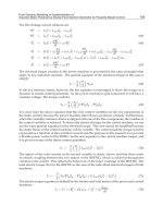
The temperature rise is calculated using this formula:
Where
:
t
2
=
temperature of winding at end of temperature
-
rise test
t
1
=
temperature of winding before temperature
-
rise test
t
a
=
temperature of cooling medium at
end of temperature
-
rise
test
R
2
=
resistance of winding at end of temperature
-
rise test
R
1
=
resistance of winding at temperature t1
Co
nstant
=
235 for copper winding:
225 for aluminum winding
What this method determines is the mean temperature rise.
This is why
an extra thermal margin of 10 K, for example, is reserved between the
mean temperature of the winding and the temperature at its hottest point.
The graph
in Fig.1.2
.C
illustrates the effect of exceeding the highest
permitted winding temperatur
e on the winding life.
7
Fig.1.2.C
-
Effect of Winding Temperature on Life of Insulation
Frame Size
Motor frame dimensions have been standardized with a uniform frame
size numbering system. This system was developed by NEMA and
specific
frame sizes have been assigned to standard motor ratings based
on enclosure, horsepower and speed.
The current standardized frames for integral horsepower induction
motors ranges from 143T to 445T. These standards cover most motors in
the range of one th
rough two hundred horsepower.
Typical example of
where you can locat
e the frame is shown in Fig 1.2.D
–
Frame
No.
Fig
1.2.D
–
Frame No
8
The numbers used to designate frame sizes have specific meanings based
on the physical size of the motor. So
me digits are related to the motor
shaft height and the remaining digit or digits relate to the length of the
motor.
The rerate, or frame size reduction programs were brought about by
advancements in motor technology relating mainly to higher temperature
ratings of insulating materials, improved magnetic steels and improved
bearings. At the present time, NEMA frame assignments do no exist for
motors larger than 445T and each manufacturer may have different frame
designations for these motors.
One addition
al suffix that may be used
on standard motors in frames
286
T and larger is an “S” inserted after the “T”. This “S
” stands for short
shaft.
In addition to having a short shaft, the motor will have a small diameter
shaft (“U” dimension) and the bearing in t
he drive shaft end of the motor
will be somewhat smaller than the equivalent long shaft motor. Short
shaft motors are intended for use only on direct coupled centrifugal
pumps and other direct coupled loads where there will not be a side pull
(overhung loa
d) exerted on the shaft by “V” belts.
Table
1.2B
–
NEMA Frame Assignment
–
Three
-
Phase Motors
OPEN MOTORS
–
GENERAL PURPOSE
NEMA
PROGRAM
HP
ORIG.
3600
RPM
1952
RERATE
1964
RERATE
ORIG.
1800
RPM
1952
RERATE
1964
RERATE
ORIG.
12
00
RPM
1952
RERATE
1964
RERA
TE
ORIG.
900
RPM
1952
RERATE
1964
RERATE
1
1.5
2
—
203
204
—
182
184
—
143T
145T
203
204
224
182
184
184
143T
145T
145T
204
224
225
184
184
213
145T
182T
184T
225
254
254
213
213
215
182T
184T
213T
3
5
7.5
224
225
254
184
213
215
145T
182T
184T
225
254
2
84
213
215
254U
182
T
184T
213T
254
284
324
215
254U
256U
213T
215T
254T
284
324
326
254U
256U
284U
215T
254T
256T
10
15
20
284
324
326
254U
256U
284U
213T
215T
254T
324
326
364
256U
284U
286U
215T
254T
256T
326
364
365
284U
324U
326U
256T
284T
286T
364
36
5
404
286U
326U
364U
284T
286T
324T
25
30
40
364S
364S
365S
286U
324S
326S
256T
284TS
286TS
364
365
404
324U
326U
364U
284T
286T
324T
404
405
444
364U
365U
404U
324T
326T
364T
405
444
445
365U
404U
405U
326T
364T
365T
50
60
75
404S
405S
444S
364US
365US
404US
324TS
326TS
364TS
405S
444S
445S
365US
404US
405US
326T
364TS*
365TS*
445
504U
505
405U
444U
445U
365T
404T
405T
504U
505
—
444U
445U
—
404T
405T
444T
100
125
150
445S
504S
505S
405US
444US
445US
365TS
404TS
405TS
504S
505S
—
444US
445US
—
404TS*
4
05TS*
444TS*
—
—
—
—
—
—
444T
445T
—
—
—
—
—
—
—
445T
—
—
200
250
—
—
—
—
444TS
445TS
—
—
—
—
445TS*
—
—
—
—
—
—
—
—
—
—
—
—
—
*
When motors are to be used with v
-
belt or chain drives, the correct frame size shown but with suffix letter S omitted.
9
Table
1.2C
–
Suffixes to NEMA Frames
TEFC
MOTORS
–
GENERAL PURPOSE
NEMA
PROGRAM
HP
ORIG.
3600
RPM
1952
RERATE
1964
RERATE
ORIG.
1800
RPM
1952
RERATE
1964
RERATE
ORIG.
1200
RPM
1952
RERATE
1964
RERATE
ORIG.
900
RPM
1952
RERATE
1964
RERATE
1
1.5
2
—
203
204
—
18
2
184
—
143T
145T
203
204
224
182
184
184
143T
145T
145T
204
224
225
184
184
213
145T
182T
184T
225
254
254
213
213
215
182T
184T
213T
3
5
7.5
224
225
254
184
213
215
182T
184T
213T
225
254
284
213
215
254U
182T
184T
213T
254
284
324
215
254U
256U
213T
21
5T
254T
284
324
326
254U
256U
284U
215T
254T
256T
10
15
20
284
324
326
254U
256U
284U
21
5
T
2
54
T
25
6
T
324
326
364
256U
284U
286U
215T
254T
256T
326
364
365
284U
324U
326U
256T
284T
286T
364
365
404
286U
326U
364U
284T
286T
324T
25
30
40
36
5
S
404S
405S
324
U
326S
364US
284TS
286TS
324TS
365
404
405
324U
326U
364U
284T
286T
324T
404
405
444
364U
365U
404U
324T
326T
364T
405
444
445
365U
404U
405U
326T
364T
365T
50
60
75
444S
445S
504S
365US
40
5
US
444US
326TS
364TS
365TS
444S
445S
504S
365US
405US
444US
326T
364TS*
365TS*
445
504U
505
405U
444U
445U
365T
404T
405T
504U
505
—
444U
445U
—
404T
405T
444T
100
125
150
505S
—
—
445US
—
—
405TS
444TS
445TS
5
05S
—
—
445US
—
—
405TS*
444TS*
445TS*
—
—
—
—
—
—
444T
445T
—
—
—
—
—
—
—
445T
—
—
*
When motors are to be us
ed with v
-
belt or chain drives, the correct frame size shown but with suffix letter S omitted.
The following explanations of the various fame suffixes used on NEMA
frame motors have been compiled for the benefit of EASA members. The
suffixes for NEMA fra
me
motors are the letters that immediately follow
the frame
numbers. Notice that more than one suffix may be used on
any
given motor.
Note:
“
D
”
dimension (shall height) of a motor or generator
in these frame sizes
equals 1 /4 the value of the first
two di
gits in the frame number.
Example: 284 frame: 28/4 = 7, D = 7"
A
—
Industrial direct
-
current machine.
B
—
Carbonator pump motors, (See NEMA
MG 1
-
2006,
18.270
–
18
.
281)
C
—
Type C face mounting on drive end.
CM
—
Face mounting dimensions are different
fro
m those for the
frame designation hav
ing the suffix letter
“
C
”
(The
l
etters
“
CH
”
are considered as one suffix and should
not be
separated.)
D
—
Type D flange mounting on drive end.
E
—
Shaft extension dimensions for elevator
motors in frames
larger than 3
2
6
T frames.
FC
—
Face mounting on opposite drive end.
FD
—
Flange mounting on opposite drive
end.
10
G
—
Gasoline pump motors. (See NEMA
MG
1
-
2006, 18.91.)
H
—
Indicates a small machine having an
“F”
dimension
larger than that of the same frame without the su
ffix
letter
“
H
”
. (See
NEMA MG 1
-
2006,
4.4.1 and 4.5.1.)
HP or HPH
—
Type P flange
-
mounted, vertical sotid
-
shaft motors
having dimensions in accor
dance with NEMA MG 1
-
2006, 18.252.
(The
l
etters
“
HP
”
and
“
HPH
”
are consid
ered
as one suffix and should not be
separated
)
J
—
Jet pump motors.
(
See NEMA MG
1
-
2006,
18.132.)
JM
—
Face
-
mounted, close
-
coupled pump mo
tor having
antifriction bearings and
dimensions in accordance
with
Table 1 of
MG 1
-
2006,
18.250. (The
l
etters
“
JM
”
are
considered as one suffix an
d should not
be separated.)
JP
—
Type C face
-
mounted, close
-
coupled
pump motor having
antifriction bearings
and dimensions in accordance with
Table 2 of MG 1
-
2006,
18.250. (The
l
etters
“
MP
”
are
considered as one suffix and should not be separated.)
K
—
Su
mp pump motors. (See NEMA
MG 1
-
2006, 18.78.)
LP or LPH
—
Type P flange
-
mounted, vertical solid
-
shaft motors
ha
v
ing dimensions in accordance with MG 1
-
2008,
18
-
251.
(The letters
“
LP
”
and
“
LPH
”
are consid
ered as one
suffix and should not be separated.)
M
—
Oil burner motors
.
(See NEMA MG 1
-
2006,
18.106.)
N
—
Oil burner
motors. (See NEMA MG
1
-
2006,
18
.
108.)
P or PH
—
Type P flange
-
mounted, vertical hollow
-
shaft motors
having dimensions in accordance with NEMA MG 1
-
2006, 18.238.
R
—
Drive end tapered shaft
extension having
dimensions in
accordance with NE
MA MG
1
-
2008,
4
.
4.2.
S
—
Standard short shaft for direct connection.
T
—
Included as part of a frame designation for
which standard
dimensions have been established.
U
—
Previously used as part of a frame de
sig
nation for which
standard dimensions had
been established.
V
—
Vertical mounting only.
VP
—
Type P flange
-
mounted, vertical solid
-
shaft motors
having dimensions in accordance with NEMA MG 1
-
2008,
18.237. (The letters
“
VP
”
are considered
as one
suffix a
nd should not be sepa
rated.)
11
X
—
Wound
-
rotor crane motors with double
shaft extension.
(See NEMA MG 1
-
2006,
18229
and
18.230.)
Y
—
Special mounting dimensions, (Dimensional diagram
must be obtained from manufacturer.)
Z
—
All mounting dimensions are stand
ard except the shaft
extension
(
s
)
. Also used
to designate machines with
double shaft
extension.
Note:
Manufacturers may use any letter preceding the
frame number, but
such a letter will have no reference
to standard mounting dimensions.
Suffix letters s
hall be added to the frame number in the
following
sequences:
Suffix Letter
Sequence
A
,
H
………………………………………………………
1
G, J,
M, N,
T,
U,
HP,
HPH,
JM,
JP,
LP,
LPH,
&
VP
2
R, S
3
C, D, P, PH
……………………………………………….
4
FC, FD
……………………………………………………
5
V ………………………………………………………….
6
E,
X,
Y,
Z
7
Example:
“
T
”
f
r
ame motor with a
“
C
”
face mounted
vertic
ally w
i
th a
nonstandard shaft extension
;
(
Sequences 2.4.8 and 7) 184TCVZ.
Note:
This material is reproduced by permission of the
National Electrical
Manufacturers Association from
NEMA
Standards, MG 1
-
2006, 4
.
2.2.
It was origi
nally published as
E
ASA Tech
Note No. 7 (
Septem
ber 1985
)
and reviewed and updated as necessary
in November 2007.
1.3
Enclosure Type
The enclosure of the motor must protect the windings, bearings, and
other mechanical parts from moisture, chemicals, mechanical damage
and abrasion from
grit. NEMA standards MG1
-
1.25 through 1.27 define
more than 20 types of enclosures under the categories of open machines,
totally enclosed machines, and machines with encapsulated or sealed
12
windings. The most commonly used motor enclosures are open
drippro
of, totally enclosed fan cooled and explosionproof.
Fig. 1.3A
–
Shows location of Enclosure Tag
The Standards for IP Codes apply to the classification of degrees of
protection provided by enclosure for all rotating machines. The
designation
used for the degree of protection consists of the letter IP
(International Protection) followed by two characteristic numerals.
13
When the degree of protection is specified by only one numeral, the
omitted numeral is replaced by the letter
X. For example, IPX5 or IP2X.
The first Characteristic Numeral indicates the degree of protection
provided by the enclosure with respect to persons and also to the parts of
the machine inside the enclosure.
The Second Characteristic Numeral indicates the
degree of protection
provided by the enclosure with respect to harmful effect due to ingress of
water.
The two characteristic numerals signify conformity with the c
onditions
indicated in Table 1.
3.
A
.
–
Degrees of Protection Indicated by the Two
Characte
ristic Numerals.
Table 1.3.A
-
Degrees of Protection indicated by the Two
Characteristic Numerals
FIRST
CHARACTERISTIC
NUMERAL
DEGREE OF PROTECTION
SECOND
CHARACTERISTIC
NUMERAL
DEGREE OF PROTECTION
0
Non
-
protected machine
0
Non
-
protected machine
1
Machine protected against solid objects
greater
than 2 inches (50 mm)
1
Machine protected against dripping
water
2
Machine protected against solid objects
greater than 0. 5 inches (12 mm)
2
Machine protected against dripping
water when tilted up to 15
o
3
Machine protected against solid objects
greater than 0.1 inches (2.5 mm)
3
Machine protected against spraying
water
4
Machine protected against solid objects
greater than 0.04 inches (1 mm)
4
Machine protected against splashing
water
5
Dust
-
protected ma
chine
5
Machine protected against water jets
6
*
Dust
-
tight machine
6
Machine protected against heavy seas
7
Machine protected against the effects of
immersion
Machine protected against continuous
submersion
*
Not include in IEC 60034
-
5, 1991 Stand
ards
Reference:
NEMA Standards MG
-
1 2006, 5.8, Tables 5
-
1, and 5
-
2.
IEC International Standard IEC 60034
-
5, 1991.
14
Classification According to Environmental Protection*
IP CODE
CLASSIFICATION
IP CODE
CLASSIFICATION
IP 00
Open Machine
IP 22
Dripproo
f guarded machine
IP 10
Semi
-
guarded machine
IP 44
Totally enclosed pipe
-
ventilated
machine
IP 12
Dripproof machine
IP 54
Totally enclosed non
-
ventilated
machine
IP 13
Splash
-
proof machine
IP 55
Water
-
proof machine
*
Reference:
NEMA Standards MG
-
1 2006
,
1.25
,
1.26
, and
1.27.
15
Open Dripproof.
The open dripproof motor (ODP) has a free exchange of air with the
ambient. Drops
of liquid or solid particles do not interfere with the
operation at any angle from 0 to 15degrees dow
nward from the vertical.
The openings are intake and exhaust ports to
accommodate interchange
of air. The open dripproof motor is designed for indoor use where the air
is fairly clean and where there is little danger of splashing liquid.
Refer
to Fig.
1.3A
–
Open Dripproof (ODP)
Fig. 1.3A
–
Open Dripproof (ODP)
Totally Enclosed Fan Cooled (TEFC).
This type of enclosure prevents the free exchange of air between the
inside and outside of the frame, but does not make the frame completely
airtight. A fan is attached to the shaft and pushes air over the frame
during its operation to help in the cooling process. The ribbed frame is
designed to increase the surface area for cooling purposes. There is also a
totally enclosed non
-
ventilated (TE
NV) design which does not use a fan,
16
but is used in situations where air is being blown over the motor shell for
cooling, such as in a propeller fan application
.
Refer to
Fig. 1.3B
–
Totally Enclosed Fan Cooled (TEFC) Motor.
Fig. 1.3B
–
Tot
ally Enclosed Fan Cooled (TEFC) Motor
Explosionproof
The explosionproof motor is a totally enclosed machine and is designed
to withstand an explosion of specified gas or vapor inside the motor
casing and prevent the ignition outside the motor by sparks
, flashing or
explosion. These motors are designed for specific hazardous purposes,
such as atmospheres containing gases or hazardous dusts. For safe
operation, the maximum motor operating temperature must be below the
ignition temperature of surrounding g
ases or vapors. Explosionproof
motors are designed, manufactured and tested under the rigid
requirements of the Underwriters Laboratories.
Hazardous location motor applications are classified by the type of
hazardous environment present, the characteristi
cs of the specific
material creating the hazard, the probability of exposure to the
environment, and the maximum temperature level that is considered safe
17
for the substance creating the hazard. The format used to define this
information is a class, group,
division and temperature code structure.
Class I (Gas or Vapor)
Group:
A
-
Acetylene
B
-
Hydrogen and Manufactured Gases
C
-
Ethyl
-
Ether, Ethylene and Cyclopropane
D
-
Gasoline, Hexane, Naphtha, Benzine, Butane, Propane,
Alcohol
Lacquer Solvent
Vapors and Natural Gas
Division II:
Hazard of fire or explosion is present only as a result of an
accident.
Motors may be dripproof or TEFC.
Class II (Dusts)
Group:
E
-
Metal Dust (Special Seals)
F
-
Carbon Black, Coal or Coke Dust
G
-
Flour, St
arch or Grain Dust
Division I:
Hazard is always present due to normal conditions. (Dust
suspended in the atmosphere.) Motors must be explosionproof
construction with Underwriter’s label.
Division II:
Motors may be TEFC or externally ventilated:
(A
)
Where dust deposits on electrical equipment prevent safe
heat dissipation.
(B)
Where deposit or dust might be ignited by arcs or
burning
material.
Class III (Fibers)
Fibers
those are
easily ignitable but not apt to be suspended in
the
air
to produce
mixtures. Examples include rayon, nylon,
cotton, saw
dust
,
and wood chips.
Division II:
Location in which easily ignitable fibers are stored or handled
TEFC
enclosure can be used if there is a minimal amount of
fibers or
flying
in the air.
18
Converting f
rom NEMA enclosure classifications to IEC enclosure
classifications
NEMA enclosure classifications are developed by NEMA and used in
the U.S./American market.
Ingress Protection
-
IP
-
ratings are developed by the European
Committee for Electro Technical
Standardization (CENELEC)
(described IEC/EN 60529), and specifies the environmental protection
and enclosure provided.
The table below can be used to convert from NEMA Enclosure Types to
IEC Enclosure Types: