An introduction to digital image processing
Bạn đang xem bản rút gọn của tài liệu. Xem và tải ngay bản đầy đủ của tài liệu tại đây (270.47 KB, 9 trang )
An Introduction to
Digital Image Processing
Bill Silver
Chief Technology Officer
Cognex Corporation, Modular Vision Systems Division
Digital image processing allows
one to enhance image features of
interest while attenuating detail
irrelevant to a given application,
and then extract useful information
about
the
scene
from
the
enhanced image. This introduction
is a practical guide to the
challenges, and the hardware and
algorithms used to meet them.
mages are produced by a variety of
physical devices, including still
and video cameras, x-ray devices,
electron microscopes, radar, and
ultrasound, and used for a variety of
purposes, including entertainment,
medical, business (e.g. documents),
industrial, military, civil (e.g. traffic),
security, and scientific. The goal in
each case is for an observer, human or
machine, to extract useful information
about the scene being imaged. An
example of an industrial application is
shown in figure 1.
Often the raw image is not directly
suitable for this purpose, and must be
processed in some way. Such
processing
is
called
image
enhancement; processing by an
observer to extract information is
called image analysis. Enhancement
and analysis are distinguished by their
output, images vs. scene information,
and by the challenges faced and
methods employed.
Image enhancement has been done
by chemical, optical, and electronic
means, while analysis has been done
mostly by humans and electronically.
I
Digital image processing is a subset
of the electronic domain wherein the
image is converted to an array of small
integers, called pixels, representing a
physical quantity such as scene
radiance, stored in a digital memory,
and processed by computer or other
digital hardware. Digital image
processing, either as enhancement for
human observers or performing
autonomous
analysis,
offers
advantages in cost, speed, and
flexibility, and with the rapidly falling
price and rising performance of
personal computers it has become the
dominant method in use.
The Challenge
An image is not a direct
measurement of the properties of
physical objects being viewed. Rather
it is a complex interaction among
several physical processes: the
intensity
and
distribution
of
illuminating radiation, the physics of
Figure 1. Digital
image
processing is
used to verify
that the correct
tire is installed
on vehicles at
GM.
the interaction of the radiation with
the matter comprising the scene, the
geometry of projection of the reflected
or transmitted radiation from 3
dimensions to the 2 dimensions of the
image plane, and the electronic
characteristics of the sensor. Unlike
for example writing a compiler, where
an algorithm backed by formal theory
exists for translating a high-level
computer language to machine
language, there is no algorithm and no
comparable theory for extracting
scene information of interest, such as
the position or quality of an article of
manufacture, from an image.
The challenge is often underappreciated by novice users due to the
seeming effortlessness with which
their own visual system extracts
information from scenes. Human
vision
is
enormously
more
sophisticated than anything we can
engineer at present and for the
foreseeable future. Thus one must be
careful not to evaluate the difficulty of
a digital image processing application
on the basis of how it looks to
humans.
Perhaps the first guiding principal is
that humans are better at judgement
and
machines
are
better
at
measurement. Thus determining the
precise position and size of an
automobile part on a conveyer, for
example, is well-suited for digital
image processing, whereas grading
apples or wood is quite a bit more
challenging (although not impossible).
Along these lines image enhancement,
which generally requires lots of
numeric computation but little
judgement, is well-suited for digital
processing.
If teasing useful information out of
the soup that is an image isn’t
challenging enough, the problem is
further complicated by often severe
time budgets. Few users care if a
spreadsheet takes 300 milliseconds to
update rather than 200, but most
industrial applications, for example,
must operate within hard constraints
imposed by machine cycle times.
There are also many applications, such
as ultrasound image enhancement,
traffic monitoring, and camcorder
stabilization, that require real-time
processing of a video stream.
To make the speed challenge
concrete, consider that the video
stream from a standard monochrome
video camera produces around 10
million pixels per second. As of this
writing the typical desktop PC can
execute
maybe
50
machine
instructions in the 100 ns. available to
process each pixel. The set of things
one can do in a mere 50 instructions is
rather limited.
On top of this many digital image
processing
applications
are
constrained by severe cost targets.
Thus we often face the engineer’s
dreaded triple curse, the need to
design something good, fast, and
cheap all at once.
Hardware
Lights
All image processing applications
start with some form of illumination,
typically light but more generally
some form of energy. In some cases
ambient light must be used, but more
typically the illumination can be
designed for the application. In such
cases the battle is often won or lost
right here—no amount of clever
software can recover information that
simply isn’t there due to poor
illumination.
Generally
one
can
choose
illumination
intensity,
direction,
spectrum (color), and continuous or
strobed. Intensity is easiest to choose
and least important; any decent image
processing algorithm should be
immune to significant variations in
contrast, although applications that
demand photometric accuracy will
require control and calibration of
intensity.
Direction is harder to choose and
more important, as any professional
photographer knows. The choices
range from point sources at one
extreme to “sky” illumination (equal
intensity from every direction) at the
other. In between are various extended
sources such as linear and ring lights.
The goal generally is to produce
consistent appearance. As a rule matte
surfaces do better with point sources
and
shiny,
specularly-reflecting
surfaces do better with diffuse,
extended sources. A design that allows
computer-controlled direction (usually
by switching LEDs on and off) is
often ideal.
Illumination color can sometimes be
used as form of image enhancement.
Its primary value is that it’s cheap and
adds zero processing time.
High speed image acquisition for
rapidly moving or vibrating objects
may require a strobe. Most cameras
have an electronic shutter which is
preferable for low- to medium-speed
acquisition, but as the exposure times
get shorter the amount of light needed
increases beyond what is reasonable to
supply continuously.
Camera
For our purposes a camera is any
device that converts a pattern of
radiated energy into a digital image
stored in a random-access memory. In
the past this operation was divided
into two pieces: conversion of energy
to electrical signal, considered to be
the camera’s function, and conversion
and storage of the signal in digital
form, performed by a digitizer. As of
this writing the distinction is
becoming blurred, and before long
cameras will feed directly to computer
memory via USB, Ethernet, or IEEE
1394 interfaces.
Camera
technology
and
the
characteristics of the resulting images
are driven almost exclusively by the
highest volume applications, which
until recently has been consumer
television. Thus most visible-light
cameras in current use for digital
image processing have resolution and
speed characteristics established by
TV broadcast standards almost a halfcentury ago.
As of this writing the typical visible
light monochrome camera would have
a resolution of 640 x 480 pixels,
produce 30 frames per second, and
support electronic shuttering and rapid
reset (the ability to reset to the
beginning of a frame at any time, to
avoid having to wait before beginning
an image acquisition). It would be
based on CCD sensor technology,
which produces good image quality
but is expensive relative to most chips
with a similar number of transistors.
Significantly higher resolution and
speed devices are available but often
prohibitively
expensive.
An
alternative is the line-scan camera,
which uses a one-dimensional sensor
and relies on scene motion to produce
an image.
For the first time ever the landscape
is changing, as high volume personal
computer multimedia applications
proliferate.
First
affected
were
monitors, which for some time have
offered higher-than-broadcast speed
and resolution. One can expect
cameras to follow, with high-speed,
high-resolution devices driven by
consumer
digital
still
camera
technology and lower-resolution, ultra
low
cost
units
driven
by
entertainment, Internet conferencing,
and
perceptual
user
interface
applications.
The low cost devices may have the
greater influence. These are based on
emerging CMOS sensor technology,
which uses the same process as most
computer chips and is therefore
inexpensive due simply to higher
process volume. Currently image
quality is not up to CCD standards,
but that is certain to change as the
technology matures.
Although monochrome images have
almost entirely disappeared in
consumer applications, they still
represent the majority in digital image
processing due primarily to camera
cost and data processing burden (for
color those 50 instructions per pixel
would drop to 17). Color cameras
come in two forms: single sensor
devices that alternate red, green, and
blue pixels in some pattern, and much
higher quality but more expensive
devices with separate sensors for each
color.
Monochrome pixels are usually 8
bits (256 gray levels), although 10and 12-bit devices are sometimes
used. Video signals tend to be noisy,
however, and careful engineering is
required to get more than 8 useful bits
out of the signal. Furthermore, robust
image analysis algorithms do not rely
on photometric accuracy, so unless the
application
calls
for
accurate
measurements of scene radiance, there
is usually little or no benefit beyond 8
bits. Wide dynamic range is more
useful than photometric accuracy, but
it is usually best achieved by using a
logarithmic response than by going to
more bits.
Color pixels are 3-vectors (this is a
fact of human physiology, not
physics). Several representations,
called color spaces, are commonly
used for representing color. The
simplest to produce is the {red, green,
blue} space (RGB), although {hue,
intensity, saturation} (HIS) may be
more useful for image analysis. For
the lower quality single-sensor
cameras, the {luminance, chroma1,
chroma2} space (YCC) is sometimes
used.
Action
Until recently the computational
burden of digital image processing for
the most part had to be handled by
dedicated hardware. Typically such
hardware consisted of plug-in cards
for PCI and/or VME backplanes,
containing one or more applicationspecific integrated circuits (ASICs)
designed for digital image processing.
The last few years has seen a move
away from dedicated hardware
towards pure software solutions, due
to the advent first of DSPs and later
general-purpose CPUs that fall at or
above the 1 billion operations per
second mark. Of these the most
significant is the development of
MMX
processors
by
Intel
Corporation.
MMX technology is well-suited for
digital image processing. Although it
is hardly alone in being so, MMX is so
widely available (all Intel-compatible
PCs made since 1997) that it is the de
facto standard for merchant digital
image processing software. This
development is likely to solidify with
the expected introduction sometime in
2000 on Merced processors of EPIC
technology, jointly developed by Intel
and Hewlett-Packard. The EPIC
architecture is superb for digital image
processing.
The full power of the new
processors is generally available only
to
skilled
assembly
language
programmers, and this is unlikely to
change in the foreseeable future.
Compiler vendors and the EPIC
architects may argue otherwise, but
direct experience in high-performance
digital
image
processing
has
consistently shown this . For timecritical applications, users should turn
to specialists.
Algorithms
We divide our discussion of digital
image processing algorithms into
image enhancement and image
analysis. The distinction is useful if
not always clear-cut.
Generally
image
enhancement
algorithms produce modified images
as output, intended for subsequent
analysis by humans or machines.
Their output behavior and execution
speed are easy to characterize, and the
basic algorithms are generally in the
public domain.
Image analysis, by contrast,
produces information that is much
smaller in quantity but much more
highly refined than an image, for
example the position and orientation
of an object. In many cases the output
is just an accept/reject decision, the
smallest quantity of information but
perhaps the highest refinement. Output
behavior and execution speed are
generally difficult and sometimes
impossible to characterize. Image
analysis algorithms are often a
vendor’s most important intellectual
property.
A simple example drawn from
human experience will make these
points concrete. Imagine focusing a
lens, which is an act of image
enhancement. It is easy to characterize
what will happen (the picture gets
sharper) and estimate how long it will
take (a couple of seconds). The results
will be fairly consistent from person to
person, and there is no great secret as
to how it’s done.
Now imagine that you are shown a
picture of a specific car and asked to
find it in a parking lot and report the
space number. This is image analysis.
If the lot is nearly empty then the
results and time needed are easy to
characterize and consistent. If the lot
is full, however, there is no telling
how long it will take or even whether
the correct answer will be reported,
since
many
cars
look
alike.
Characterizing the output space
number as a function of the input
distribution
of
scene
radiance
measurements
is
essentially
impossible. Results may vary widely
from person to person, and an
individual’s “proprietary” methods
may have a large bearing on the
outcome.
The difficulty in characterizing the
behavior of automated image analysis
leads to a level of risk that is far
greater than that of more typical
software development projects, which
are already notoriously risky. The best
ways to manage the risk are to rely on
experienced professional developers,
to share the risk between vendors and
their clients, and to characterize
performance empirically using a large
database of stored images.
Image Enhancement
Table 1 shows a classification of
digital image enhancement algorithms
in common use. The classification
given is useful but neither complete
nor unique. The algorithms are
broadly divided into two classes, point
transforms
and
neighborhood
operations.
Point transforms produce output
images where each pixel is some
function of a corresponding input
pixel. The function is the same for
every pixel, and is often derived from
global statistics of the image. With
neighborhood operations, each output
pixel is a function of a set of
corresponding input pixels. This set is
called a neighborhood because it is
usually some region surrounding a
corresponding center pixel, for
example a 3x3 neighborhood.
Point transforms generally execute
rapidly but are limited to global
transformations such as adjusting
overall image contrast. Neighborhood
operations can implement frequency
and shape filtering and other
sophisticated enhancements, but
execute more slowly because the
neighborhood must be recomputed for
each output pixel.
Pixel mapping point transforms
include a large set of enhancements
that are useful with scalar-valued
pixels (e.g. monochrome images).
Often these are implemented by a
single software routine (or hardware
module) that uses a lookup table.
Lookup tables are fast and can be
programmed for any function, offering
the ultimate in generality at reasonable
speed. MMX and similar processors,
however, can perform a variety of
functions much faster by direct
computation than by table lookup, at a
cost of increased software complexity.
TABLE 1.
IMAGE ENHANCEMENT ALGORITHMS
Point transforms
• pixel mapping
− gain/offset control
− histogram specification
− thresholding
• color space transforms
• time averaging
Pixel maps are most useful when the
function is computed based on global
statistics of the image. One can
process an image to have a desired
gain and offset, for example, based on
the mean and standard deviation, or
alternatively, the minimum and
maximum, of the input.
Histogram
specification
is a
powerful
pixel
mapping
point
transform wherein an input image is
processed so that it has the same
distribution of pixel values as some
reference image. The pixel map for
histogram specification is easily
computed from histograms of the
input and reference images. Histogram
specification is a useful enhancement
prior to an analysis step whose goal is
some sort of comparison between the
input and the reference.
Thresholding is a commonly used
enhancement whose goal is to segment
an image into object and background.
A threshold value is computed above
(or below) which pixels are considered
“object” and below (or above) which
“background”.
Sometimes
two
thresholds are used to specify a band
of values that correspond to object
pixels. Thresholds can be fixed but are
best computed from image statistics.
Thresholding can also be done using
neighborhood operations. In all cases
the result is a binary image—only
black and white are represented, with
no shades of gray.
Thresholding has a long but
checkered his tory in digital image
processing. Up until the mid 1980’s
Neighborhood operations
• linear filtering
− smoothing
− sharpening
• boundary detection
• non-linear filtering
− median filter
− morphology
• re-sampling
− resolution pyramids
− coordinate transforms
thresholding was a nearly universal
first step in image analysis, due to the
high cost of hardware needed to do
gray-scale processing. As hardware
cost dropped and sophisticated new
algorithms
were
developed,
thresholding became less important.
When thresholding works it can be
quite effective, because it directly
identifies
objects
against
a
background,
and
eliminates
unimportant
shading
variation.
Unfortunately in most applications
scene shading is such that objects
cannot be separated from background
by any threshold, and even when an
appropriate threshold value exists in
principal it is notoriously difficult to
find it automatically. Furthermore,
thresholding destroys useful shading
information and applies essentially
infinite gain to noise at the threshold
value, resulting in a significant loss of
robustness and accuracy.
As a general rule, given the
performance of modern processors
and
gray-scale image analysis
algorithms, thresholding and image
analysis algorithms that depend on
thresholding are best avoided.
Color space conversion is used to
convert between, for example, the
RGB space provided by a camera to
the HIS space needed by an image
analysis algorithm. Accurate color
space conversion is computationally
expensive,
and
often
crude
approximations are used in timecritical applications. These can be
quite effective, but it is a good idea to
understand the tradeoffs between
speed and accuracy before choosing
an algorithm.
Time averaging is the most
effective method of handling very low
contrast images. Pixel maps to
increase image gain are of limited
utility because they affect signal and
noise
equally.
Neighborhood
operations can reduce noise but at the
cost of some loss in image fidelity.
The only way to reduce noise without
affecting the signal is to average
multiple images over time. The
amplitude of uncorrelated noise is
attenuated by the square root of the
number of images averaged. When
time averaging is combined with a
gain-amplifying pixel map, extremely
low contrast scenes can be processed.
The principal disadvantage of time
averaging is the time needed to
acquire multiple images from a
camera.
Linear filters are the best understood
of the neighborhood operations, due to
the
extensively
developed
mathematical framework of signal
theory dating back 200 years to
Fourier. Linear filters amplify or
attenuate selected spatial frequencies,
can achieve such effects as smoothing
and sharpening., and usually form the
basis of re-sampling and boundary
detection algorithms.
Linear filters can be defined by a
convolution operation, where output
pixels are obtained by multiplying
each neighborhood pixel by a
corresponding element of a likeshaped set of values called a kernel,
and then summing those products.
Figure 2a, for example, shows a
rather noisy image of a cross within a
circle.
Convolution
with
the
smoothing (low pass) kernel of figure
2b produces figure 2c. In this example
the neighborhood is 25 pixels arranged
in a 5x5 square. Note how the highfrequency noise has been attenuated,
but at a cost of some loss of edge
sharpness. Note also that the kernel
elements sum to 1.0 for unity gain.
The smoothing kernel of figure 2b is
a 2D Gaussian approximation. The 2D
Gaussian is among the most important
functions used for linear filtering. Its
frequency response is also a Gaussian,
which results in a well-defined passband and no ringing. Kernels that
approximate the difference of two
Gaussians of different size make
excellent band-pass and high-pass
filters.
Figure 2d illustrates the effect of a
band-pass filter based on a difference
of Gaussian approximation using a
10x10 kernel. Note that both the high
frequency noise and the low frequency
uniform regions have been attenuated,
hardware than FFTs, is simpler to
implement, and has little trouble with
boundary conditions.
Boundary detection has an extensive
history and literature, which ranges
from simple edge detection to
complex algorithms that might more
properly be considered under image
analysis. We somewhat arbitrarily
consider boundary detection under
image enhancement because the goal
is to emphasize features of interest
(the boundaries) and attenuate
.004 .016 .023 .016 .004
.016 .062 .094 .062 .016
.023 .094 .140 .094 .023
2e .062 .016
.016 .062 .094
.004 .016 .023 .016 .004
2a
2b
2d
2c
2f
Figure 2. An image can be enhanced to reduce noise or emphasize boundaries
leaving only the mid-frequency
components of the edges.
Linear filters can be implemented
by direct convolution or in the
frequency domain using FFTs. While
frequency
domain
filtering
is
theoretically more efficient, in practice
direct convolution is almost always
preferred. Convolution, with its use of
small integers and sequential memory
everything else.
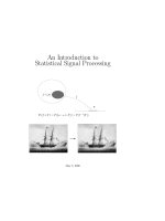
The shading produced by an object
in an image is among the least reliable
of an object’s properties, since
shading is a complex combination of
illumination,
surface
properties,
projection geometry, and sensor
characteristics. Image discontinuities,
on the other hand, usually correspond
directly
to
object
surface
Figure 3. Image discontinuities usually correspond to physical object features, while
shading is often unreliable.
addressing, is a better match for digital
discontinuities (e.g. edges), since the
other factors tend not to be
discontinuous. Image discontinuities
are generally consistent geometrically
(i.e. in shape) even when not
consistent photometrically (see figure
3). Thus identifying and localizing
discontinuities, which is the goal of
boundary detection, is one of the most
important digital image processing
tasks.
Boundaries are usually defined to
occur at points where the rate of
change of image brightness is a local
maximum, i.e. at peaks of the first
derivative or, equivalently, zerocrossings of the second derivative. On
a discrete grid such points can only be
estimated, which can be done with
linear filters designed to estimate first
or second derivative. The difference of
Gaussian of figure 2d, for example, is
a second derivative estimator, and
boundaries show up as zero-crossings
that occur at the sharp black-to-white
transition points in the figure.
Figure 2e shows the output of a first
derivative estimator, often called a
gradient operator, applied to a noisefree version of figure 2a. The gradient
operator consists of a pair of linear
filters designed to estimate first
derivative horizontally and vertically,
which gives components of the
gradient vector. The figure shows
gradient magnitude, with boundaries
defined to occur at the local
magnitude peaks.
Crude edge detectors simply mark
image pixels corresponding to
gradient magnitude peaks or secondderivative
zero-crossings.
Sophisticated boundary detectors
produce organized chains of boundary
points, with sub-pixel position and
boundary orientation (accurate to a
few degrees) at each point. The best
commercially
available
boundary
detectors are also tunable in spatial
frequency response over a wide range,
and operate at high speed.
Non-linear filters designed to pass
or block desired shapes rather than
spatial frequencies have been found
useful for digital image enhancement.
The first we consider is the median
filter, whose output at each pixel is the
median of the corresponding input
neighborhood. Roughly speaking the
effect of a median filter is to attenuate
image features smaller in size than the
neighborhood and pass image features
larger than the neighborhood.
Figure 2f shows the effect of a 3x3
median filter on the noisy image of
figure 2a. Note that the noise, which
generally results in features smaller
than 3x3 pixels, is strongly attenuated.
The 4 basic morphology operations
have many uses, one of which is
shown in figure 4. In the figure, the
input image on the left is opened with
a circular probe and a rectangular
probe, resulting in the images shown
on the right. One might imagine the
probe to be a paintbrush, with the
output being everything the brush can
paint while placed wherever in the
Figure 4. A morphology “opening” operation acts as a shape filter, whose
behavior is controlled by a “probe”.
Unlike the linear smoothing filter of
figure 2c, however, note that there is
no significant loss in edge sharpness,
since all of the cross and circle
features are much larger than the
neighborhood. Thus a median filter is
often superior to linear filters for noise
reduction.
One
of
the
main
dis advantages of the median filter,
however, is that it is very expensive to
compute compared to linear filters,
and the disparity gets worse as the
neighborhood size increases.
Morphology refers to a broad class
of non-linear shape filters. Like the
linear filters the operation is defined
by a matrix of elements applied to
input image neighborhoods, but
instead of a sum of products, a
minimum or maximum of sums is
computed. These operations are called
erosion and dilation, and the matrix of
elements is usually referred to as a
probe rather than a kernel.
Erosion followed by a dilation using
the same probe is called an opening,
and dilation followed by erosion is
called closing.
input it will fit (i.e. entirely on black
with no white showing). Notice how
the opening operation with appropriate
probes is able to pass certain shapes
and block others.
For simplicity the example of figure
4 illustrates opening as a binary
(black/white) operation, but in general
the 4 morphology operations are
defined on gray-level images, with the
concept of probe fitting defined on 2D
surfaces in 3-space.
Digital re-sampling refers to a
process of estimating the image that
would have resulted had the
continuous distribution of energy
falling on the sensor been sampled
differently. A different sampling,
perhaps at a different resolution or
orientation, is often useful.
One of the most important forms of
digital re-sampling obtains a series of
images at successively coarser
resolution. Such a series of images is
called
a
resolution
pyramid.
Conventionally each image in the
series is half the resolution of the
previous in each dimension (1/4 the
number of pixels), but other choices
are often preferable. Resolution is
reduced by a combination of low-pass
filtering and sub-sampling (selecting
every n th pixel).
A resolution pyramid forms the
basis of many image analysis
algorithms that follow a coarse-to-fine
strategy. The coarse resolution images
allow rough information to be
extracted quickly, without being
distracted and confused by fine and
often irrelevant detail. The algorithm
proceeds to finer resolution images to
localize and refine this information.
Another important class of resampling algorithms are coordinate
transforms, which can shift by subpixel amounts, rotate and size images,
and convert between Cartesian and
polar representations. Output pixel
values are interpolated from a
neighborhood of input values. Three
methods is common use are nearest
neighbor, which is the fastest, bilinear
interpolation, which is more accurate
but slower and suffers some loss of
high frequency components, and cubic
convolution, which is very accurate
but slowest.
Image Analysis
It’s only a slight oversimplification
to say that the fundamental problem of
image analysis is pattern recognition,
the purpose of which is to recognize
image patterns corresponding to
physical objects in the scene, and
determine their pose (position,
orientation, size, etc.). Often the
results of pattern recognition are all
that’s needed, for example a robot
guidance system supplies an object’s
pose to a robot, and in other cases a
pattern recognition step is needed to
find an object so that it can, for
example, be ni spected for defects or
correct assembly.
Pattern recognition is hard because a
specific object can give rise to a wide
variety of images depending on all of
the factors previously discussed.
Furthermore, similar-looking objects
may be present in the scene that must
be ignored, and the speed and cost
targets may be severe.
Blob analysis is one of the earliest
methods widely used for industrial
pattern recognition. The premise is
simple—classify image pixels as
object or background by some means,
join the classified pixels to make
discrete objects using neighborhood
connectivity rules, and compute
various moments of the connected
objects to determine object position
(1st moments), size (0th moment), and
orientation (principal axis of inertia,
based on 2nd moments).
The advantages of blob analysis
include high speed, sub-pixel accuracy
(in cases where the image is not
subject to degradation), and the ability
to tolerate and measure variations in
orientation and size. Disadvantages
include inability to tolerate touching
or
overlapping
objects,
poor
performance in the presence various
forms of image degradation, inability
to determine the orientation of certain
shapes (e.g. squares), and poor ability
to discriminate amongst similarlooking objects.
Perhaps the most serious problem,
however, is that in practice the only
generally reliable method ever found
for separating object from background
was to arrange for the objects to be
entirely brighter or entirely darker
than the background. This requirement
so severely limits the range of
potential applications that before long
other methods for pattern recognition
were developed.
Normalized correlation (NC) has
been the dominant method for pattern
recognition in industry over the last
decade. It is a member of a class of
algorithms known as template
matching, which starts with a training
step wherein a picture of an object to
be located (the template) is stored. At
run-time the template is compared to
like-sized subsets of the image over a
range of positions, with the position of
greatest match taken to be the position
of the object. The degree of match (a
numerical value) can be used for
inspection, as can comparisons of
individual pixels between the template
and image at the position of best
match.
NC is a gray-scale match function
that uses no thresholds and ignores
variation in overall pattern brightness
and contrast. It is ideal for use in
template matching algorithms.
NC template matching overcomes
many of the limitations of blob
analysis —it can tolerate touching or
overlapping objects, performs well in
the presence of various forms of
image degradation, and the NC match
value is useful in some inspection
applications.
Most
significantly,
perhaps, objects need not be separated
from background by brightness,
enabling a much wider range of
applications.
Unfortunately, NC gives up some of
the significant advantages of blob
analysis, particularly the ability to
tolerate and measure variations in
orientation and size. NC will tolerate
small variations, typically a few
degrees and a few percent (depending
on the specific template), but even
within this small range of orientation
and size the accuracy of the results
falls off rapidly.
These limitations have been partly
overcome by using re-sampling
methods to extend NC by rotating and
scaling the templates so as to measure
orientation and size. These methods
have been expensive, however, and by
the time computer cost and
performance made them practical they
were superceded by the far superior
geometric methods described below.
The Hough transform is a method
for recognizing parametrically defined
curves such as lines and arcs, as well
as general patterns. It starts with an
edge detection step, which makes it
more tolerant of local and non-linear
shading variations than NC. When
used to find parameterized curves the
Hough transform is quite effective; for
general patterns NC may have a speed
and accuracy advantage, as long as it
can handle the shading variations.
Geometric pattern matching (GPM)
is replacing NC template matching as
the method of choice for industrial
pattern recognition. Template methods
suffer from fundamental limitations
imposed by the pixel grid nature of the
template itself. Translating, rotating,
and sizing grids by non-integer
amounts requires re-sampling, which
is time consuming and of limited
accuracy. This limits the pose
accuracy that can be achieved with
template-based pattern recognition.
Pixel grids, furthermore, represent
patterns using gray-scale shading,
which as we’ve observed is often not
reliable.
GPM avoids these limitations by
representing an object as a geometric
shape, independent of shading and not
tied to a discrete grid. Sophisticated
boundary detection is used to turn the
pixel grid produced by a camera into a
conceptually real-valued geometric
description that can be translated,
rotated, and sized quickly and without
loss of fidelity. When combined with
advanced pattern training and highspeed, high-accuracy pattern matching
modules, the result is a truly general
purpose pattern recognition and
inspection method.
A well-designed GPM system
should be as easy to train as NC
template matching, yet offer rotation,
size, and shading independence. It
should be robust under conditions of
low contrast, noise, poor focus, and
missing and unexpected features.
Pattern
recognition
time
is
application-specific, as is typical of
image analysis methods. For a
ballpark figure, to locate a 150x150
pixel pattern in a 500x500 field of
view with 360° orientation uncertainty
might require 30 – 50 milliseconds on
PCs current as of this writing. Always
test speed for a specific application,
however, since times can vary
considerably beyond any specified
range.
GPM is capable of much higher
pose accuracy than any templatebased method, as much as an order of
magnitude better when orientation and
size vary. Table 2 shows what can be
achieved in practice when patterns are
reasonably close to the training image
in shape, and not too degraded.
Accuracy is generally higher for larger
patterns; the example of table 2
assumes a pattern in the 150x150 pixel
range.
TABLE 2
GEOMETRIC PATTERN MATCHING ACCURACY
Translation
±0.025 pixels
Rotation
±0.02 degrees
Size
±0.05 percent
GPM is also capable of providing
detailed data on differences between a
trained pattern and an object being
inspected. This difference data is also
rotation,
size,
and
shading
independent.
Putting it All Together
Often a complete digital image
processing system combines many of
the above image enhancement and
analysis methods. In the following
example, the goal is to inspect objects
by looking for differences in shading
between an object and a pre-trained,
defect-free example called a golden
template.
Simply subtracting the template
from an image and looking for
differences does not work in practice,
since the variation in gray-scale due to
ordinary and acceptable conditions
can be as great as that due to defects.
This is particularly true along edges,
where slight (i.e. subpixel) mis registration of template and image can
give rise to large variation in grayscale. Variation in illumination and
surface reflectance can also give rise
to differences that are not defects, as
can noise.
A practical method of template
comparison for inspection uses a
combination of enhancement and
analysis steps to distinguish shading
variation due to defects from that due
to ordinary conditions:
1. A pattern recognition step (e.g.
GPM) determines the relative
pose of the template and image.
2. A digital re-sampling step uses
the pose to achieve precise
alignment of template to image.
3. A pixel mapping step using
histogram
specification
compensates for variations in
illumination
and
surface
reflectance.
4. The absolute difference of the
template and image is computed.
5. A threshold is used to mark pixels
that may correspond to defects.
Each pixel has a separate
threshold, with pixels near edges
having a higher threshold because
their gray-scale is more uncertain.
6. A blob analysis or morphology
step is used to identify those
clusters of marked pixels that
correspond to true defects.
Further Reading
Digital image processing is a broad
field with an extensive literature. This
introduction could only summarize
some of the more important methods
in common use, and may suffer from a
bias towards industrial applications.
We have entirely ignored image
compression,
3D
reconstruction,
motion, texture, and many other
significant topics.
The following are suggested for
further reading. Ballard and Brown
gives an excellent survey of the field,
while the others provide more
technical depth.
Ballard, D.H. and Brown, C.M.
(1982). Computer Vision. PrenticeHall, Englewood Cliffs, New Jersay
Horn, B.K.P. (1986). Robot Vision.
MIT
Press,
Cambridge,
Massachusetts
Pratt, W.K. (1991). Digital Image
Processing, 2nd Ed. John Wiley &
Sons, New York, NY.
Rosenfeld, A. and Kak, A.C. (1982).
Digital Picture Processing, Vol. 1
and 2, 2nd Ed., Academic Press,
Orlando, Florida.
COGNEX®
Cognex Corporation
One Vision Drive, Natick, MA
01760
Tel: (508) 650-3000
Fax: (508) 650-3333
Web: www.cognex.com
Email:
© Copyright 2000,
Cognex Corpration.
All rights reserved.