AN0709 system level design considerations when using I2CTM serial EEPROM devices
Bạn đang xem bản rút gọn của tài liệu. Xem và tải ngay bản đầy đủ của tài liệu tại đây (92.15 KB, 5 trang )
M
AN709
System Level Design Considerations When Using
I2CTM Serial EEPROM Devices
Author:
Rick Stoneking
Microchip Technology Inc.
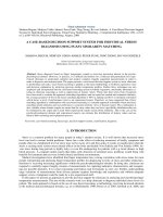
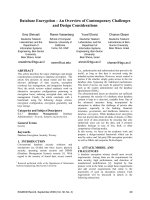
FIGURE 1:
RECOMMENDED HARDWARE
CONFIGURATION
µC
INTRODUCTION
Developing systems that implement the I2C protocol for
communicating with serial EEPROM devices requires
that a certain key factors be considered during the
hardware and software development phase if the system is to achieve maximum compatibility and robustness. This application note discusses these factors,
both hardware and software, to help insure that an optimal system design is achieved. This application note is
limited to single master systems and therefore does not
specifically address the unique requirements of a multimaster system. However, the concepts presented in
this application note apply equally as well to those systems.
CONDITIONS TO BE CONSIDERED
Due to the bi-directional nature of the data bus devices
operate in both transmit and receive modes at various
times. In order to make this bi-directional operation
possible the protocol must define specific times at
which any given device may transmit or receive, as well
as define specific points in the protocol where the functions are swapped (i.e. the transmitter becomes the
receiver and the receiver becomes the transmitter).
There are a number of events which could potentially
cause this sender/receiver ‘synchronization’ to be lost,
which can result in situations where:
• Both the master and the slave are in a send
mode.
• Both the master and the slave are in a receive
mode.
• The ‘bit count’ is off by one or more bits between
the master and the slave.
These events, which include the microcontroller being
reset during I2C communication, brown-out conditions,
excessive noise on the clock or data lines, and
improper bus input levels during power up, can be
effectively neutralized through a combination of hardware and software techniques.
EEPROM
VDD
SCL
SDA
INSURING ‘BUS-FREE’ DURING
POWER-UP
In order to insure that the internal state machine of the
serial EEPROM is correctly initialized at power up, it is
crucial to guarantee that the device sees a ‘bus-free’
condition (defined as both SCL and SDA being high)
until VDDmin has been reached. The ideal way to guarantee this is through the use of pull-up resistors on both
the SDA and SCL lines. In addition, these pull-ups
should be tied to the same voltage source as the VDD
pin of the device. In other words is the device VDD is
supplied from the main positive supply rail then the
SCL and SDA pull-ups should be connected to that
same supply rail (as opposed to being connected to a
microcontroller I/O pin, for example). Figure 1 is an
example of the recommended hardware configuration.
The reasoning behind doing this is the same for both
adding the pull-up to the SCL line and for utilizing the
same supply for the VDD pin and the pull-ups. As anyone who has had any experience with CMOS logic
already knows, it is necessary to ensure that all inputs
are tied either high or low, since allowing a CMOS input
to float can lead to a number of problems. If the SCL
line does not have a pull-up, or if the pull-ups are not
tied to the VDD supply rail, then conditions occur, however briefly, where the SCL/SDA inputs are floating with
respect to the VDD supply voltage. When possible this
condition should be avoided.
I2C is a trademark of Philips Semiconductors
1999 Microchip Technology Inc.
DS00709B-page 1
AN709
When it is not possible to add a pullup resistor to the
SCL line (i.e. the hardware design has already been
finalized) then the firmware should be configured to
either: 1) drive the SCL line high during power up or,
2) float the SCL input during power up.
Of these two options, the first is the recommended
method, despite typical concerns regarding latch-up,
because it does not negatively impact the battery life in battery powered applications. Microchip Technology’s serial
EEPROM devices, like all CMOS devices, are susceptible
to latch-up, however latch-up does not occur until currents
in excess of 100mA are injected into the pin. Typical microcontrollers are not capable of supply currents of this magnitude, therefore the risk of latch-up is extremely low.
The second option is also acceptable but does lead to
a brief increase in the current draw of the device during
the time period in which the SCL pin is floating with
respect to VDD. This increase can be significant in comparison to the normal standby current of the device and
can have a detrimental affect on battery life in power
sensitive applications.
In all cases it is important that the SCL and SDA lines
not be actively held low while the EEPROM device is
powered up. This can have an indeterminable effect on
the internal state machine and, in some cases, the
state machine may fail to correctly initialize and the
EEPROM will power up in an incorrect state.
Another improper practice which should be pointed out is
the driving of the SDA line high by the microcontroller pin
rather than tri-stating the pin and allowing the requisite
pullup resistor to pull the bus up to the high state. While
this practice would appear harmless enough, and indeed
it is as long as the microcontroller and EEPROM device
never get out of sync, there is a potential for a high current situation to occur. In the event that the microcontroller and EEPROM should get out of sync, and the
EEPROM is outputting a ‘low’ (i.e. sending an ACK or
driving a data bit of ‘0’) while the microcontroller is driving
a high then a low impedance path between VDD and VSS
is created and excessive current will flow out of the microcontroller I/O pin and into the EEPROM SDA pin. The
amount of current that flows is limited only by the IOL
specification of the microcontoller’s I/O pin. This high current state can obviously have a very detrimental effect on
battery life, as well as potentially present long term reliability problems associated with the excess current flow.
FORCING INTERNAL RESET VIA
SOFTWARE
In all designs it is recommended that a software reset
sequence be sent to the EEPROM as part of the microcontrollers power up sequence. This sequence guarantees that the EEPROM is in a correct and known state.
Assuming that the EEPROM has powered up into an
incorrect state (or that a reset occurred at the microcontroller during communication), the following sequence
(which is further explained below) should be sent in
order to guarantee that the serial EEPROM device is
properly reset:
DS00709B-page 2
•
•
•
•
START Bit
Clock in nine bits of ‘1’
START Bit
STOP Bit
The first START bit will cause the device to reset from
a state in which it is expecting to receive data from the
microcontroller. In this mode the device is monitoring
the data bus in receive mode and can detect the
START bit which forces an internal reset.
The nine bits of ‘1’ are used to force a reset of those
devices that could not be reset by the previous START
bit. This occurs only if the device is in a mode where it is
either driving an acknowledge on the bus (low), or is in
an output mode and is driving a data bit of ‘0’ out on the
bus. In both of these cases the previous START bit
(defined as SDA going low while SCL is high) could not
be generated due to the device holding the bus low. By
sending nine bits of ‘1’ it is guaranteed that the device will
see a NACK (microcontroller does not drive the bus low
to acknowledge data sent by EEPROM) which also
forces an internal reset.
The second START bit is sent to guard against the rare
possibility of an erroneous write that could occur if the
microcontroller was reset while sending a write command to the EEPROM, and, the EEPROM was driving
an ACK on the bus when the first START bit was sent. In
this special case if this second START bit was not sent,
and instead the STOP bit was sent, the device could initiate a write cycle. This potential for an erroneous write
occurs only in the event of the microcontroller being
reset while sending a write command to the EEPROM.
The final STOP bit terminates bus activity and puts the
EEPROM in standby mode.
This sequence does not effect any other I2C devices
which may be on the bus as they will simply disregard
it as an invalid command.
SUMMARY
This application note has presented ideas that are fundamental in nature, yet not always obvious, to the utilization of I2C serial EEPROM devices. Ideally the
hardware/software engineer(s) takes these ideas into
consideration during system development and design
accordingly. It is recommended that the software reset
sequence detailed in this application note be added to
the system initilization code of any system that utilizes
an I2C serial EEPROM device.
REFERENCES
‘I2C-Bus Specification’, Philips Semiconductors, January
1992
‘The I2C-Bus and How to Use It’, Philips Semiconductors,
April 1995
1999 Microchip Technology Inc.
AN709
NOTES:
1999 Microchip Technology Inc.
DS00709B-page 3
Note the following details of the code protection feature on PICmicro® MCUs.
•
•
•
•
•
•
The PICmicro family meets the specifications contained in the Microchip Data Sheet.
Microchip believes that its family of PICmicro microcontrollers is one of the most secure products of its kind on the market today,
when used in the intended manner and under normal conditions.
There are dishonest and possibly illegal methods used to breach the code protection feature. All of these methods, to our knowledge, require using the PICmicro microcontroller in a manner outside the operating specifications contained in the data sheet.
The person doing so may be engaged in theft of intellectual property.
Microchip is willing to work with the customer who is concerned about the integrity of their code.
Neither Microchip nor any other semiconductor manufacturer can guarantee the security of their code. Code protection does not
mean that we are guaranteeing the product as “unbreakable”.
Code protection is constantly evolving. We at Microchip are committed to continuously improving the code protection features of
our product.
If you have any further questions about this matter, please contact the local sales office nearest to you.
Information contained in this publication regarding device
applications and the like is intended through suggestion only
and may be superseded by updates. It is your responsibility to
ensure that your application meets with your specifications.
No representation or warranty is given and no liability is
assumed by Microchip Technology Incorporated with respect
to the accuracy or use of such information, or infringement of
patents or other intellectual property rights arising from such
use or otherwise. Use of Microchip’s products as critical components in life support systems is not authorized except with
express written approval by Microchip. No licenses are conveyed, implicitly or otherwise, under any intellectual property
rights.
Trademarks
The Microchip name and logo, the Microchip logo, FilterLab,
KEELOQ, microID, MPLAB, PIC, PICmicro, PICMASTER,
PICSTART, PRO MATE, SEEVAL and The Embedded Control
Solutions Company are registered trademarks of Microchip Technology Incorporated in the U.S.A. and other countries.
dsPIC, ECONOMONITOR, FanSense, FlexROM, fuzzyLAB,
In-Circuit Serial Programming, ICSP, ICEPIC, microPort,
Migratable Memory, MPASM, MPLIB, MPLINK, MPSIM,
MXDEV, PICC, PICDEM, PICDEM.net, rfPIC, Select Mode
and Total Endurance are trademarks of Microchip Technology
Incorporated in the U.S.A.
Serialized Quick Turn Programming (SQTP) is a service mark
of Microchip Technology Incorporated in the U.S.A.
All other trademarks mentioned herein are property of their
respective companies.
© 2002, Microchip Technology Incorporated, Printed in the
U.S.A., All Rights Reserved.
Printed on recycled paper.
Microchip received QS-9000 quality system
certification for its worldwide headquarters,
design and wafer fabrication facilities in
Chandler and Tempe, Arizona in July 1999. The
Company’s quality system processes and
procedures are QS-9000 compliant for its
PICmicro® 8-bit MCUs, KEELOQ® code hopping
devices, Serial EEPROMs and microperipheral
products. In addition, Microchip’s quality
system for the design and manufacture of
development systems is ISO 9001 certified.
2002 Microchip Technology Inc.
M
WORLDWIDE SALES AND SERVICE
AMERICAS
ASIA/PACIFIC
Japan
Corporate Office
Australia
2355 West Chandler Blvd.
Chandler, AZ 85224-6199
Tel: 480-792-7200 Fax: 480-792-7277
Technical Support: 480-792-7627
Web Address:
Microchip Technology Australia Pty Ltd
Suite 22, 41 Rawson Street
Epping 2121, NSW
Australia
Tel: 61-2-9868-6733 Fax: 61-2-9868-6755
Microchip Technology Japan K.K.
Benex S-1 6F
3-18-20, Shinyokohama
Kohoku-Ku, Yokohama-shi
Kanagawa, 222-0033, Japan
Tel: 81-45-471- 6166 Fax: 81-45-471-6122
Rocky Mountain
China - Beijing
2355 West Chandler Blvd.
Chandler, AZ 85224-6199
Tel: 480-792-7966 Fax: 480-792-7456
Microchip Technology Consulting (Shanghai)
Co., Ltd., Beijing Liaison Office
Unit 915
Bei Hai Wan Tai Bldg.
No. 6 Chaoyangmen Beidajie
Beijing, 100027, No. China
Tel: 86-10-85282100 Fax: 86-10-85282104
Atlanta
500 Sugar Mill Road, Suite 200B
Atlanta, GA 30350
Tel: 770-640-0034 Fax: 770-640-0307
Boston
2 Lan Drive, Suite 120
Westford, MA 01886
Tel: 978-692-3848 Fax: 978-692-3821
Chicago
333 Pierce Road, Suite 180
Itasca, IL 60143
Tel: 630-285-0071 Fax: 630-285-0075
Dallas
4570 Westgrove Drive, Suite 160
Addison, TX 75001
Tel: 972-818-7423 Fax: 972-818-2924
Detroit
Tri-Atria Office Building
32255 Northwestern Highway, Suite 190
Farmington Hills, MI 48334
Tel: 248-538-2250 Fax: 248-538-2260
Kokomo
2767 S. Albright Road
Kokomo, Indiana 46902
Tel: 765-864-8360 Fax: 765-864-8387
Los Angeles
18201 Von Karman, Suite 1090
Irvine, CA 92612
Tel: 949-263-1888 Fax: 949-263-1338
China - Chengdu
Microchip Technology Consulting (Shanghai)
Co., Ltd., Chengdu Liaison Office
Rm. 2401, 24th Floor,
Ming Xing Financial Tower
No. 88 TIDU Street
Chengdu 610016, China
Tel: 86-28-6766200 Fax: 86-28-6766599
China - Fuzhou
Microchip Technology Consulting (Shanghai)
Co., Ltd., Fuzhou Liaison Office
Unit 28F, World Trade Plaza
No. 71 Wusi Road
Fuzhou 350001, China
Tel: 86-591-7503506 Fax: 86-591-7503521
China - Shanghai
Microchip Technology Consulting (Shanghai)
Co., Ltd.
Room 701, Bldg. B
Far East International Plaza
No. 317 Xian Xia Road
Shanghai, 200051
Tel: 86-21-6275-5700 Fax: 86-21-6275-5060
China - Shenzhen
150 Motor Parkway, Suite 202
Hauppauge, NY 11788
Tel: 631-273-5305 Fax: 631-273-5335
Microchip Technology Consulting (Shanghai)
Co., Ltd., Shenzhen Liaison Office
Rm. 1315, 13/F, Shenzhen Kerry Centre,
Renminnan Lu
Shenzhen 518001, China
Tel: 86-755-2350361 Fax: 86-755-2366086
San Jose
Hong Kong
Microchip Technology Inc.
2107 North First Street, Suite 590
San Jose, CA 95131
Tel: 408-436-7950 Fax: 408-436-7955
Microchip Technology Hongkong Ltd.
Unit 901-6, Tower 2, Metroplaza
223 Hing Fong Road
Kwai Fong, N.T., Hong Kong
Tel: 852-2401-1200 Fax: 852-2401-3431
New York
Toronto
6285 Northam Drive, Suite 108
Mississauga, Ontario L4V 1X5, Canada
Tel: 905-673-0699 Fax: 905-673-6509
India
Microchip Technology Inc.
India Liaison Office
Divyasree Chambers
1 Floor, Wing A (A3/A4)
No. 11, O’Shaugnessey Road
Bangalore, 560 025, India
Tel: 91-80-2290061 Fax: 91-80-2290062
Korea
Microchip Technology Korea
168-1, Youngbo Bldg. 3 Floor
Samsung-Dong, Kangnam-Ku
Seoul, Korea 135-882
Tel: 82-2-554-7200 Fax: 82-2-558-5934
Singapore
Microchip Technology Singapore Pte Ltd.
200 Middle Road
#07-02 Prime Centre
Singapore, 188980
Tel: 65-334-8870 Fax: 65-334-8850
Taiwan
Microchip Technology Taiwan
11F-3, No. 207
Tung Hua North Road
Taipei, 105, Taiwan
Tel: 886-2-2717-7175 Fax: 886-2-2545-0139
EUROPE
Denmark
Microchip Technology Nordic ApS
Regus Business Centre
Lautrup hoj 1-3
Ballerup DK-2750 Denmark
Tel: 45 4420 9895 Fax: 45 4420 9910
France
Microchip Technology SARL
Parc d’Activite du Moulin de Massy
43 Rue du Saule Trapu
Batiment A - ler Etage
91300 Massy, France
Tel: 33-1-69-53-63-20 Fax: 33-1-69-30-90-79
Germany
Microchip Technology GmbH
Gustav-Heinemann Ring 125
D-81739 Munich, Germany
Tel: 49-89-627-144 0 Fax: 49-89-627-144-44
Italy
Microchip Technology SRL
Centro Direzionale Colleoni
Palazzo Taurus 1 V. Le Colleoni 1
20041 Agrate Brianza
Milan, Italy
Tel: 39-039-65791-1 Fax: 39-039-6899883
United Kingdom
Arizona Microchip Technology Ltd.
505 Eskdale Road
Winnersh Triangle
Wokingham
Berkshire, England RG41 5TU
Tel: 44 118 921 5869 Fax: 44-118 921-5820
01/18/02
2002 Microchip Technology Inc.